

Winco 1800-12, 1800-13, 700-13, 1800-14, 1800-15 Owner's Manual
...
I
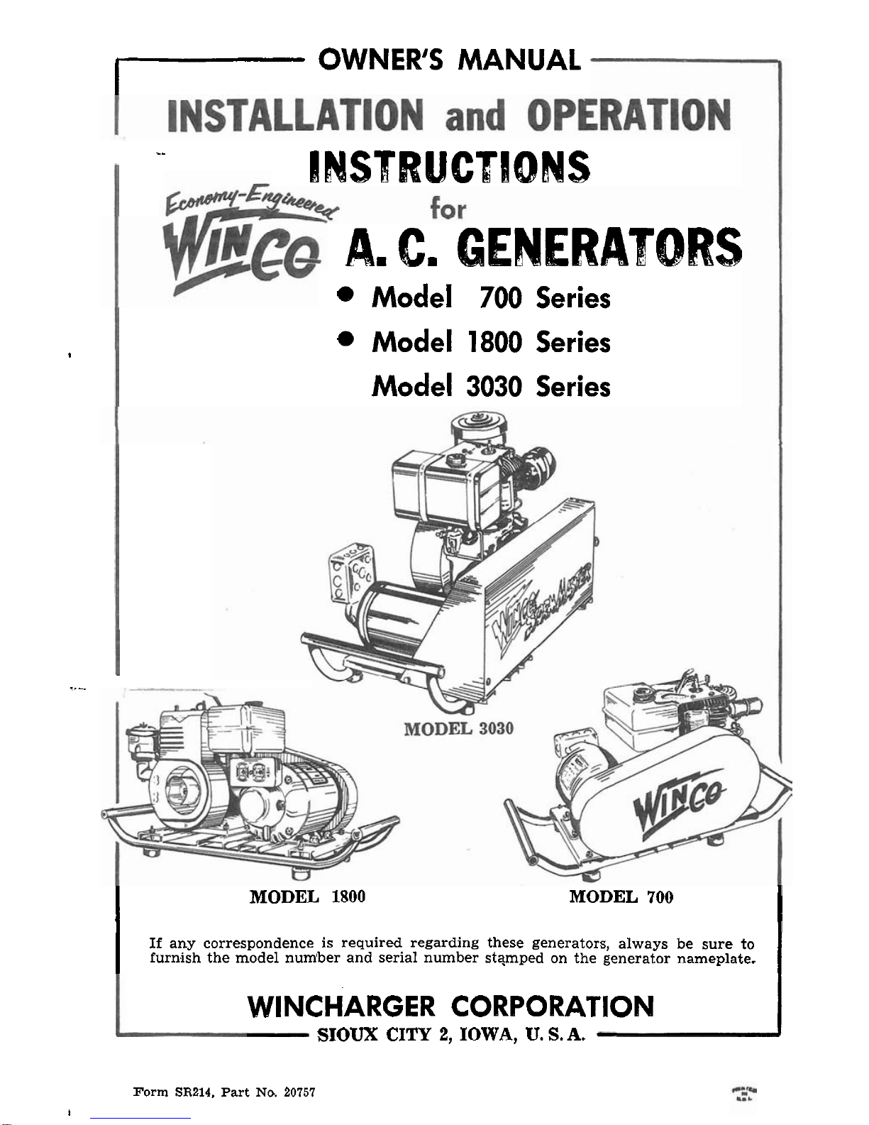
OWNER'S MANUAL
..
ILMSBRUCTIOFIIS
A.
C.
GENERATORS
8
Model
700
Series
Model
1800
Series
I
Model
3030
Series
:.-
I
MODEL
1800
MODEL
700
I
I
If
any correspondence is required regarding these generators, always be sure to
furnish the model number and serial number
stqmped on the generator nameplate.
I
WINCHARGER CORPORATION
1
SIOUX CITY
2,
IOWA,
U.
S.
A.
Form
SR214,
Part
No.
20757
I
INSTALLATION AND OPERATION INSTRUCTIONS
FOR
WlNCO
A.C.
GENERATORS
Model 700 Series
Model 1800 Series
Model 3030 Series
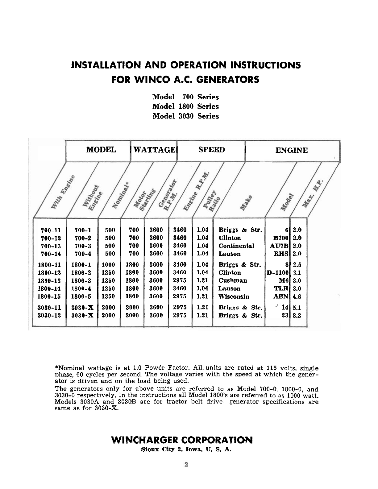
MODEL WATTAGE SPEED ENGINE
700-11 700-1
500
700 3600
3460 1.04
Briggs
&
Sir. 6 2.0
700-12
700-2
500
700 3600
3460 1.04
Clinton
B700
2.0
700-13 700-3 500 700 3600 3460 1.04 Continental
AU7B
2.0
700-14 700-4 500 700 3600 3460 1.04
Lauson
RHS
2.n
1800-11
1800-1
1000 1800
3600 3460 1.04
Briggs&Str. 8 2.5
1800-12 1800-2 1250
1800
3600 3460 1.04
Clipton D-1100 3.1
1800-13 1800-3
1350
1800 3600
2975 1.21
Cushman M6 3.0
1800-14 1800-4
1250 1800
3600 3460 1.04
Lauson
TLW
3.0
1800-15
1800-5
1350 1800 3600
2975 1.21
Wisconsin
ABN
4.6
3030-11
3030-X
2000 3000
3600 2975 1.21
Briggs& Str.
"
14 5.1
3030-12
3030-X 2000 3000 3600
2975
1.21
Briggs&Str. 23 8.3
*Nominal wattage is at
1.0
Power Factor. All. units are rated at
115
volts, single
phase,
60
cycles per second. The voltage varies with the speed at which the gener-
ator
is
driven and on the load being used.
The generators only for above units are referred to as Model
700-0, 1800-0,
and
3030-0
respectively. In the instructions all Model
1800's
are referred to as
1000
watt.
Models
3030A
and
303OB
are for tractor belt drive-generator specifications are
same as for
3030-X.
WINCHARGER CORPORATION
Sioux City 2, Iowa,
U.
S.
A.
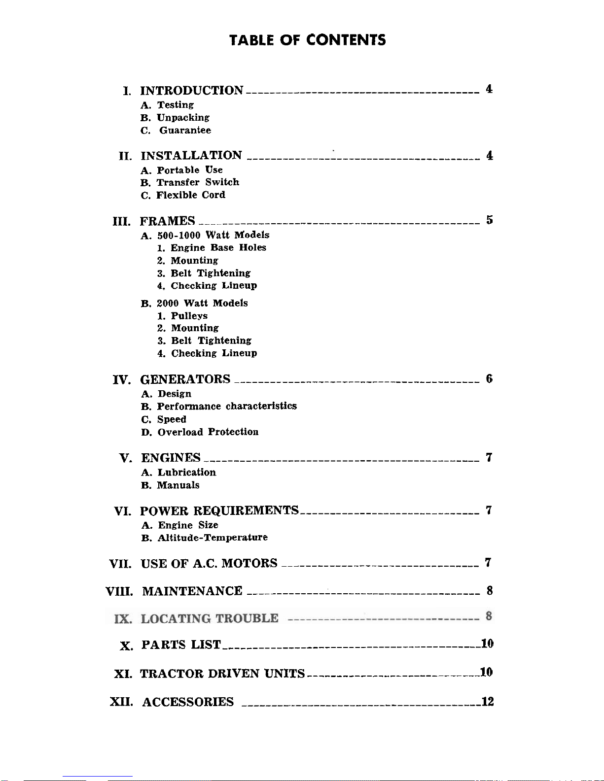
TABLE OF CONTENTS
I. INTRODUCTION
4
A.
Testing
B. Unpacking
C. Guarantee
11. INSTALLATION
--------------
........................
4
A.
Portable Use
B. Transfer Switch
C. Flexible Cord
111. FRAMES----------------------------------------
5
A.
500-1000 Watt Models
1.
Engine Base Holes
2.
Mounting
3.
Belt Tightening
4.
Checking Lineup
B. 2000 Watt Models
1.
Pulleys
2.
Mounting
3.
Belt Tightening
4.
Checking Lineup
IV. GENERATORS
........................................
6
A.
Design
B. Performance characteristics
C. Speed
D. Overload Protection
V.
ENGINES----------------------------------------
7
A.
Lubrication
B. Manuals
VI. POWER REQUIREMENTS
..............................
7
A.
Engine Size
B. Altitude-Temperature
VII. USE OF A.C. MOTORS
.................................
7
VIII. MAINTENANCE
.......................................
8
X.
PARTS LIST
...........................................
10
XI. TRACTOR DRIVEN UNITS
.............................
10
XII. ACCESSORIES 12
Models
700, 1800,3030
8.
INTRODUCTION
Each generator is carefully inspected at
the factory and "run-in" until the brushes
are satisfactorily seated. The unit is then
carefully checked for correct output under
average operating conditions. NO GENERATOR IS SHIPPED UNLESS IT PRODUCES ITS FULL RA'IYCD CAPACITY,
NOR UNTIL IT HAS PASSED RIGID INSPECTION TESTS. If uwon installation a
new generator does noi work properly,
check all of the electrical connections and
the generator speed before concluding that
the generator is not performing satisfactorily.
when unpacking the machine, be sure to
inspect it carefully to see that no damages
occilrred in transit. If damages are noted,
notify the transportation company immediately and have them write the
nature of the damages on the freight
bill, so that a claim can be filed if necessary.
Each
AC generator is guaranteed to be
free from defects in workmanship and
material arising in connection with normal
usage for a period of one year, provided
that the owner returns his guarantee registration card within
10 days after purchasing the unit. Fill in the information
requested on the registration- card and
return it,
so
the guarantee can be issued
to
you.
etc. directly into the outlet terminals. The
outlet box is equipped with lock-type receptacles which prevent the plugs from
working loose.
To operate permanently
connecte~
motors, etc. on a standby basis, provision
must be made to
prevent the generated
current from "feeding back" into the power
line where it could be a hazard to linemen
and other users.
ALL WIRING
IS
TO BE DONE IN CON-
FORMANCE
WITH
-NATIONAL
ELEC-
TRICAL CODE AND WITH STATE AND
LOCAL REGULATIONS.
The conductor from the transfer switch
to the generator can be made of No.
14
type
S
cord for distance up to 25 feet. Always
use the twist-lock plug for making these
connections permanently.
When starting the generator, turn off the
load or reduce it. If too many light bulbs
are left on, the generator may fail to build
up voltage.
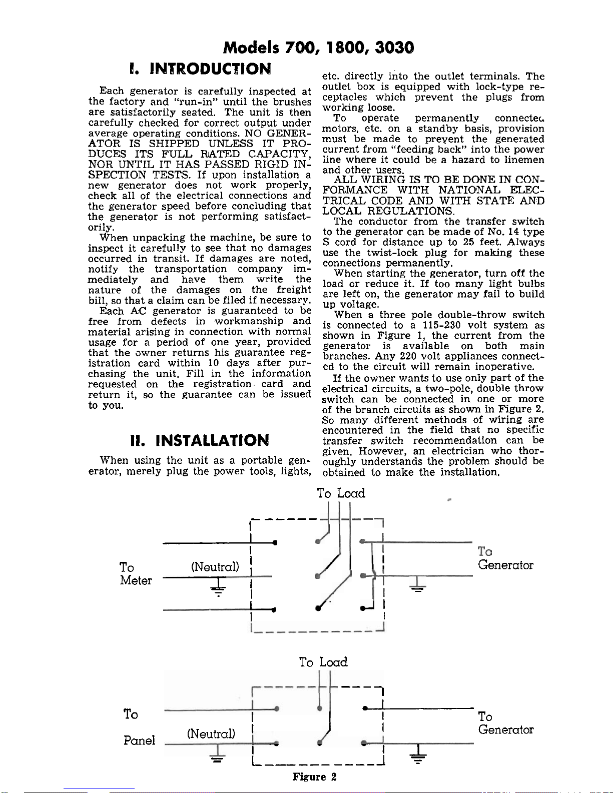
When a three pole double-throw switch
is connected to a
115-230 volt system as
shown in Figure
1,
the current from the
generator is available on both main
branches. Any
220 volt appliances connect-
ed to the circuit will remain inoperative.
If the owner wants to use only part of the
electrical circuits, a two-pole, double throw
switch can be connected in one or more
of the branch circuits as shown in Figure 2.
So
many different methods of wiring are
encountered in the field that no specific
II.
INSTALLATION
transfer switch recommendation can be
given. However, an electrician who thor-
when using the unit as a portable gen- oughly understands the problem should be
erator, merely plug the power tools, lights, obtained to make the installation.
To
Load
I-
-----
I
To
-
(Neutral)
I
I
Generator
Meter
I_
-
I
-
-
7
I
I.
I
I
To
Load
----
I
To
i
I
I
To
(Neutral)
I
I
Generator
Panel
-
I
-
-
L
----------
1
+
Figure
2
 Loading...