

Page 1

Remote Control Instructions For
EWX124, ST1224, T41224, TR1224, TRP1224, WR1224
Contents:
1. Function and characteristics
2. Main technical parameters
3. Model classification and function introduction
4. The flashing of the indicator light
5. Receiver wiring diagram
6. Precautions
7. Maintenance and repair
8-10. Instructions for TR1224 & TRP1224
10. Trouble shooting
1. Function and characteristics
(1)Function
Our wireless remote control is mainly used to replace the manual remote lead to
operate an electric winch from longer/safer distance away from the winch.
(2)Characteristics
The remote control uses 2.4G wireless radio technology. Its features include easy
to use settings, low power, automatic shutdown, stable performance,
anti-interference capability.
2. Main technical parameters
(1)Transmitter power: Powered by a single battery ( 9v or 12v)
(2)Receiver operating voltage: 9V-36V
(3)Remote control distance:0-50m
(4)Remote control angle:0-360°
(5)Frequency band range maximum & minimum:
433MHz:433.05-434.79MHz
2.4G:2.40-2.48GHz
Normal operating conditions;
Temperature environment:
—40 ∽ +45℃
Relative humidity:
≤95%RH(25℃)
Page 2
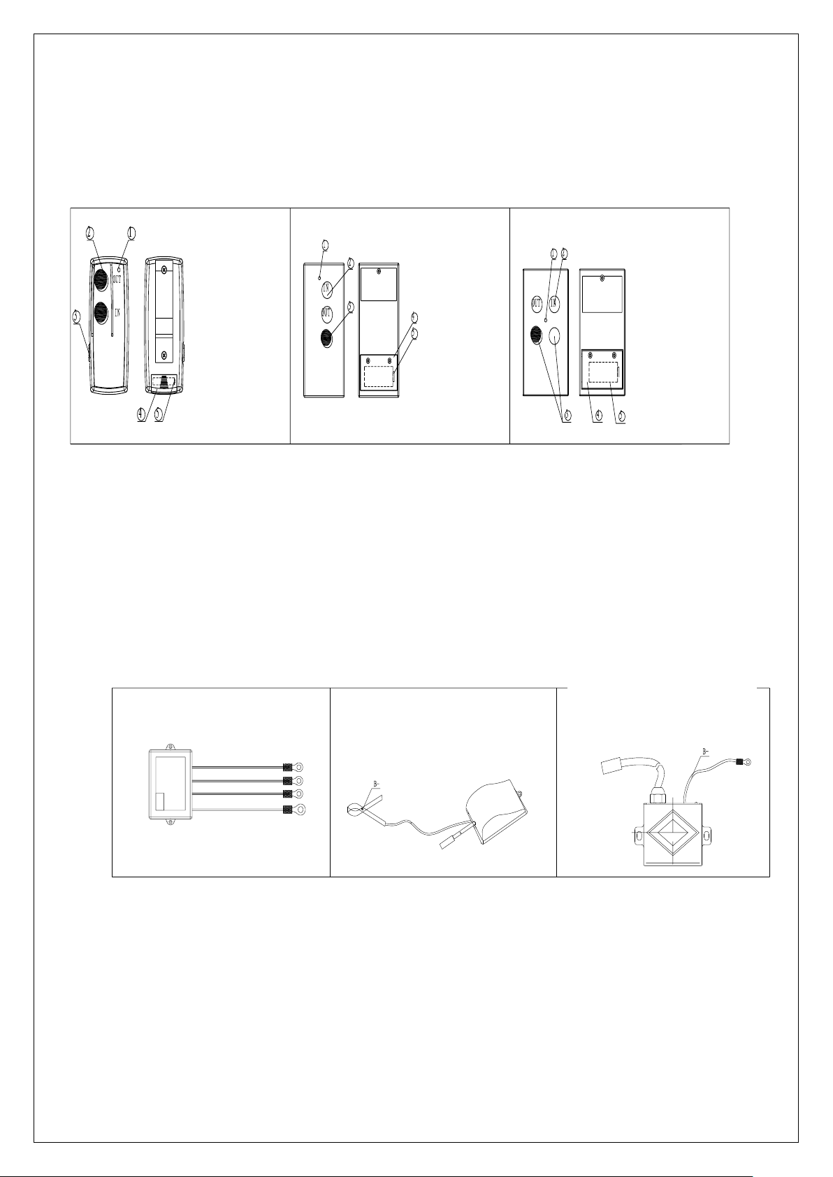
3. Model classification and function introduction
Model classification and function(transmitter)
Instructions:
1.Install batteries into transmitter
2.Press/Slide the ON/OFF switch to ON position on the transmitter (handset).
3.The signal LED indicator flashes to indicate the status of the remote control and the electric winch.
Tips:
After use, please turn off the transmitter.
Model classification and function(receiver)
Instructions:
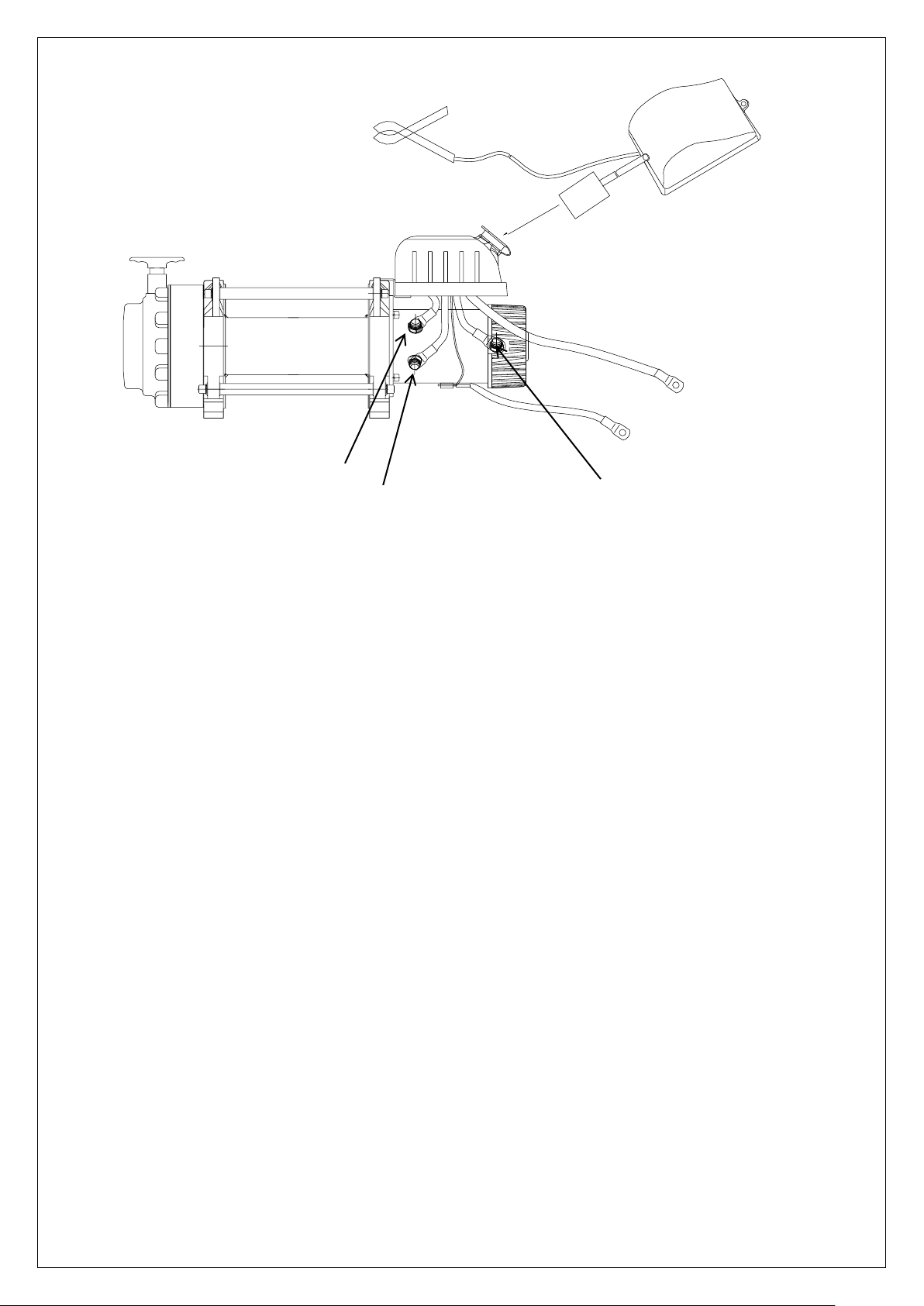
Connect up the receiver to the solenoid (see above illustration), then connect the power supply to the winch.
Tips:
① Once a connection is established, please connect the receivers earth to the nearest earth connection,
(for better results earth to the battery negative terminal).
② When using an external receiver, if the electric control box socket is out of reach, the remote control
receiver needs to be extended. If the electric control box socket is a 3 pin socket a 3 core cable is
required. If the electric control box socket is 4 pin a 4 core cable is required.
③ The external receiver should be installed directly into the control box or socket (if 3pin or 4 Pin
version). If the mounting clip or earth lead is attached, please connect the mounting clip to the
①signal indicator
(red or green)
②IN/OUT
Operation button
③on/off switch
④battery cover
⑤battery
①
signal indicator
(red or green)
②IN/OUT
Operation
button
③on/off switch
④battery cover
⑤battery
①
signal indicator
(red or green)
②IN/OUT
Operation button
③on/off switch
④battery cover
⑤battery
External Remote Control
Receiver
External Remote Control
Receiver
Page 3
negative terminal of the power supply of the battery. Note!!! DO NOT attached earth clip or lead
to motor terminals or solenoid.
4. The flashing of the indicator light
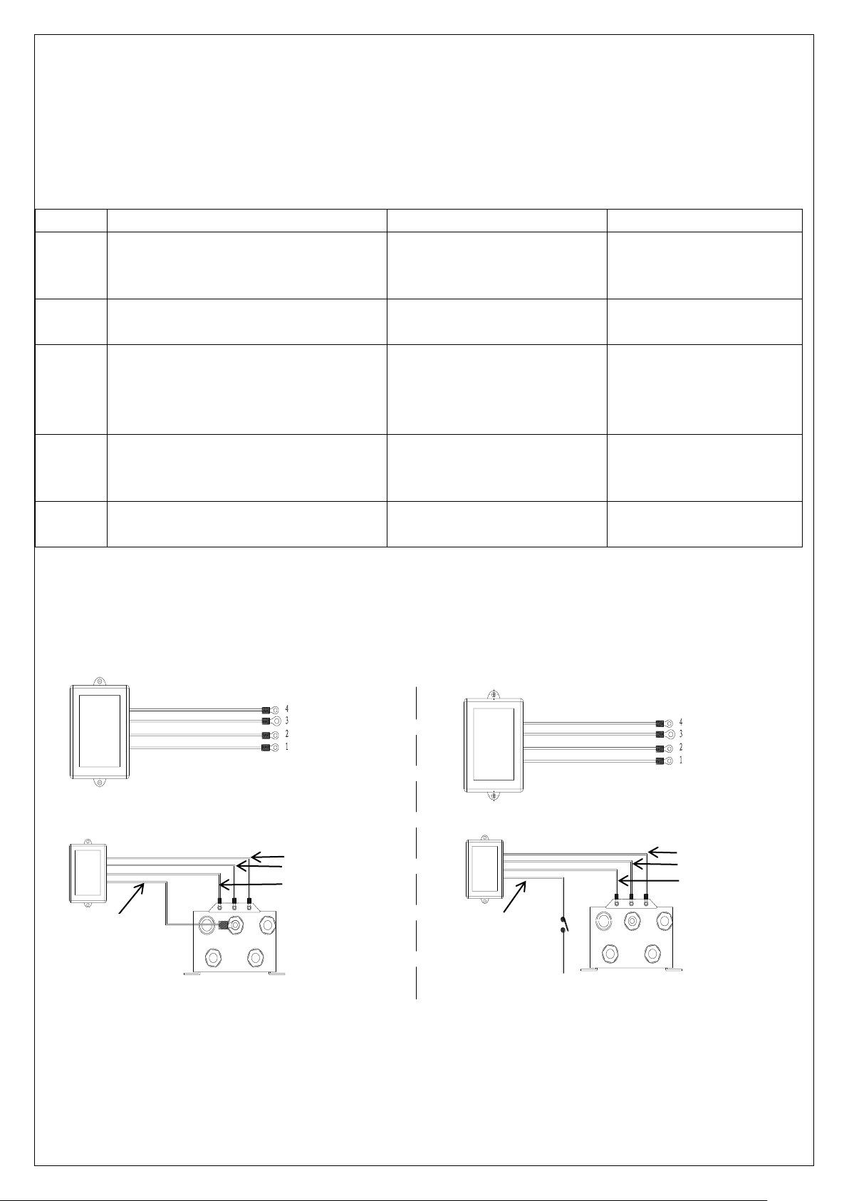
5. Receiver wiring diagram
(1)The remote control system is operated by the remote control transmitter and
communicated via the receiver to control the winch direction in or out.
(2)wiring diagram:
Wiring one Wiring two
Number
Flash mode
Fault
Solution
1
The light is red 1:1 indicator
Signal disconnected or
poorly received
Check surrounding
Area or pairing
2
The light is red 2:2 indicator
The transmitter battery
is low
Change the battery in
the transmitter
3
The light is red 3:3 indicator
Mains battery power is
low
Start the vehicle or
check the mains battery
Supply for voltage
4
The solid red LED light is on
the connection is
completed or OK
it can be used
normally
5
The solid green LED light is on
IN/OUT operating
1.white out
2.yellow in
3.red B+
4.black B-
1.white out
2.yellow in
3.red B+
4.black B-
white
black
yellow
red
red
key
B+
white
black
yellow
Page 4
6.Precautions:
(1)After the transmitter is turned on, the red LED should illuminate. A continuous green light will
illuminate when the IN / OUT buttons are pressed.
(2)There is 1sec-3sec signal detection time when starting. If the winches main power supply fails or
Transmitter exceeds the maximum distance the transmitter indicator red LED will regularly flash.
(3)The maximum operating voltage of the remote control receiver is 36V, so please use a reasonable
choice of power.
(4)When installing and adjusting the winch, especially when finishing the wire rope,
make sure that the transmitter power (handset) is turned off.
(5)The transmitter and the receiver of the remote control are paired and cannot be
interchanged unless the code is lost.
(6)If you do not use the remote control for a long time, you should remove the battery
from the transmitter. Replace the battery or replace if there is loss of power.
7. Maintenance and repair
7.1 When the transmitter (handset) is replaced with a similar or a second transmitter is required.
Please use this pairing method
Pairing method:
1.Turn off power to both receiver and transmitter (handset)
2.Turn on power to transmitter (handset)
3.Press and hold IN and OUT buttons simultaneously
4.Turn on power to receiver
5.Release IN and OUT buttons
6.Solid red LED should illuminate
7.Press IN or OUT button
8.Solid green LED should illuminate
9.If red LED flashes repeat pairing process from Step 7.1
External 3-pin plug connection
B-
External control box socket
Red
Black
(B-)
Red
(F2)
Yellow
(F1)
Blue
(A)
Motor’s earthing
terminal
Page 5
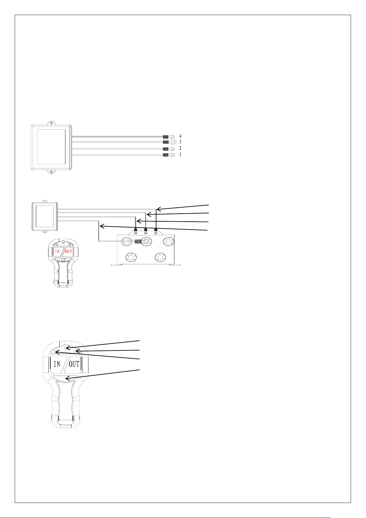
8.Working principle and wiring diagram For T41224, TR1224, & TRP1224
8.1This remote control communicates the information from the transmitter to the
receiver to control the winch direction in and out.
8.2 wiring diagram:
9.Using method and Precautions
9.1Remote control transmitter function introduction
(1)Power button: Press 2sec-3sec, the power of the transmitter is turned on, and the
solid blue power LED indicator will illuminate.
(2)Press the transmitter IN button and the RED LED indicator light illuminates;
(3)Press the transmitter OUT button, the GREEN LED indicator light illuminates.
1. yellow IN
2. white OUT
3. red B+
4. black B-
White
Black
Yellow
Red
Power LED Indicator
Out LED Indicator
In LED Indicator
Power Button
Page 6

9.2. Precautions:
(1)After the transmitter is turned on, the blue led light illuminates. Red/Green led illuminates when the
IN / OUT buttons are pressed;
(2)There is 1sec-3sec signal detection time when starting. If the winches main power supply fails or
Transmitter exceeds the maximum distance the transmitter indicator red LED will regularly flash;
(3)The maximum operating voltage of remote control is 36V, so please use a reasonable choice of
Power.
(4)When installing and adjusting the winch, especially when finishing the wire rope, make sure that the
transmitter power is turned off.;
(5)The transmitter and receiver are paired and cannot be interchanged unless the code is lost;
(6)If you do not use the transmitter for a long period of time, please remove the batteries.
Replace the battery if loss of power.
10. Maintenance and repair
10.1 When the transmitter is replaced, the same type of transmitter is required for pairing. The pairing
method is as follows:
Pairing method:
1.Turn off power to both receiver and transmitter (handset)
2.Turn on power to transmitter (handset)
3.Press and hold IN and OUT buttons simultaneously
4.Turn on power to receiver
5.Release IN and OUT buttons
6.Solid red/green LED should flash simultaneously
7.After approx. 2-3s blue LED should turn solid
8.Press IN or OUT button
9.Solid red/green LED should illuminate
10.If red/blue LED flashes repeat pairing process from Step 10.1
11. Trouble Shooting
During use, if the red led flashes, the control system has detected a fault and needs to be
looked in to. The reason for the problem is as follows:
(1)The distance between the receiver and the transmitter is greater than the maximum stable distance;
(reduce the distance between receiver and transmitter)
(2)External environment may have an effect on the signal, if this happens or signal is lost between
transmitter and receiver (use manual remote lead);
(3)Possible short circuit in the electronic control box,(check inside electronic control box or vehicle
power supply).
(4)Replace transmitter battery
(5)Receiver internal failure, replace the receiver and re-code;
(Pairing method according to 10.1 or 7.1)
Page 7
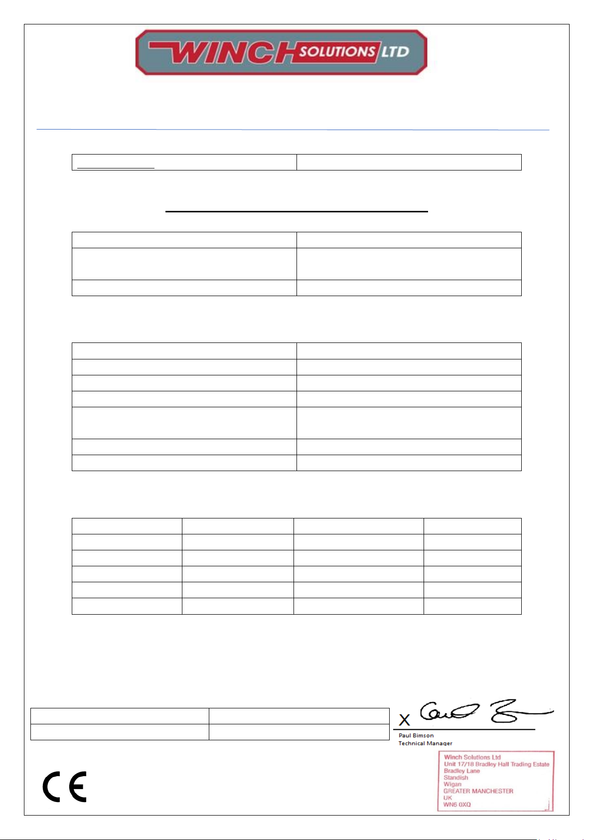
Supplier: Winch Solutions Ltd, Unit 17/18 Bradley Hall Trad Est, Standish Wigan, WN6 0XQ,
United Kingdom
EC Declaration of Conformity
Equipment
Wireless Remote Set 2.4Ghz
Model
EWX124, WR1224, W41224, TR1224, TR41224, TRP1224,
ST1224
Serial Number
WSL2400001-WSL2499999
In accordance with the following directives:
R&TTE
1995/5/EC
Radio Equipment Directive
2014/53/EU RED
EMC
2004/104/EEC ETSI EN301 489-1/-3
Radio
ETSI EN 300 440-2 ESTI EN 300 220 v1.1.1
Safety
Low Voltage Directive 2014/35/EU
EN ISO 13849-1 2008, BS EN 60950-1
Health
EN 62479
Spectrum
2.40-2.48GHz, 433.05-434.79MHz
In accordance with Article(s):
Article Number
Standard
Document Number
Date of Issue
3.1 (a)
EN 62479
UNIA2018120508HR-01
12.12.2018
3.1 (a)
EN 60950-1
UNIA2018120508SR-01
12.12.2018
3.1 (b)
ETSI EN 301 489-1/-3
UNIA2018120508-1ER-01
12.12.2018
3.2
ETSI EN 300 440
UNIA2018120508-2ER-01
12.12.2018
3.2
ETSI EN 300 220
UNIA2018120508-3ER-01
12.12.2018
I hereby declare that the equipment named above has been designed and manufactured to comply with relevant sections of the
above referenced specifications. The products comply with the essential requirements of the relevant directives and standards.
This certificate is only valid for the product(s) and configuration described in conjunction with details test data and with all
applicable legal requirements of this product.
Date:
16/08/2019 15:28
Issuing Country:
United Kingdom
Certificate No.
UNIA2018120508EC-01-WSL
 Loading...