

TECHNICAL
TECHNICAL
GUIDE
GUIDE
80% SINGLE STAGE ECM
RESIDENTIAL GAS FURNACES
MULTI-POSITION STANDARD & LOW NOx
MODELS: TM8E, TMLE
NATURAL GAS
40 - 130 MBH INPUT
Due to continuous product improvement, specifications are
subject to change without notice.
Visit us on the web at
www.upgnet.com
Additional rating information can be found at
www.ahridirectory.org
WARRANTY SUMMARY
A 20-year limited warranty on heat exchangers in residential
applications.
A 10-year warranty on the heat exchanger in commercial
applications.
Standard 5-year limited Parts warranty.
Extended lifetime heat exchanger and 10-year limited
parts warranty when product is registered online within
90 days of purchase for replacement or closing for new
home construction.
See Limited Warranty certificate in Users Information Manual for details.
5597959-BTG-A-0119
DESCRIPTION
These compact units employ induced combustion, reliable hot
surface ignition and high heat transfer aluminized tubular heat
exchangers. The units are factory shipped for installation in
upflow applications and may be converted for horizontal or
downflow applications.
These furnaces are designed for residential installation in a
basement, closet, alcove, attic, recreation room, or garage and
are also ideal for commercial applications. All units are factory
assembled, wired, and tested to assure safe, dependable, and
economical installation and operation.
These units are Category I listed and may be common vented
with another gas appliance as allowed by the National Fuel Gas
Code.
FEATURES
• Easily applied in upflow, horizontal left or right, or downflow
installation with minimal conversion necessary.
• Compact, easy to install, ideal height 33" tall cabinet.
• Blower-off delay for cooling SEER improvement.
• Easy access to controls to connect power/control wiring.
• Built-in, high level self diagnostics with fault code displays
standard on integrated control module for reliable operation.
• Low unit amp requirement for easy replacement application.
• All models are convertable to use propane (LP) gas.
• Electronic Hot Surface Ignition saves fuel cost with increased
dependability and reliability.
• 100% shut off main gas valve for extra safety.
• 5 speed direct drive Standard ECM blower motor.
• 24V, 40 VA control transformer and blower relay supplied for
add-on cooling.
• Hi-tech tubular aluminized steel primary heat exchanger.
• Timed on, adjustable off blower capability for maximum
comfort.
• Blower door safety switch.
• Solid removable bottom panel allows easy conversion.
• Low NOx models have been designed to meet specific code
requirements.
• Airflow leakage less than 1% of total airflow at duct performance testing conditions.
• No knockouts to deal with, making installation easier.
• Movable duct connector flanges for application flexibility.
• Quiet inducer operation.
• Inducer rotates for easy conversion of venting options.
• Fully supported blower assembly for easy access and
removal of blower.
• External air filters used for maximum flexibility in meeting
customers’ IAQ needs.
• Venting applications - may be installed as a common vent
with other gas-fired appliances or use a masonry chimney.
• 1/4 turn knobs provided for easy door removal.
• High-efficiency blower motor for lower electrical power usage
and improved A/C SEER ratings.
• Insulated blower compartment for thermal and acoustic
performance.
FOR DISTRIBUTION USE ONLY - NOT TO BE USED AT POINT OF RETAIL SALE
5597959-BTG-A-0119
5,*+76,'(
´
´
5(7851(1'
´
´
/()76,'(
´
´
´
%
´
9HQW&RQQHFWLRQ
2XWOHW
(OHFWULFDO
(QWU\
*DV3LSH
(QWU\
7KHUPRVWDW
:LULQJ
´'LDPHWHU
9HQW&RQQHFWLRQ
2XWOHW
&
)5217
$
´
(OHFWULFDO
(QWU\
9HQW
&RQQHFWLRQ
2XWOHW
*DV3LSH
(QWU\
7KHUPRVWDW
:LULQJ
%
6833/<(1'
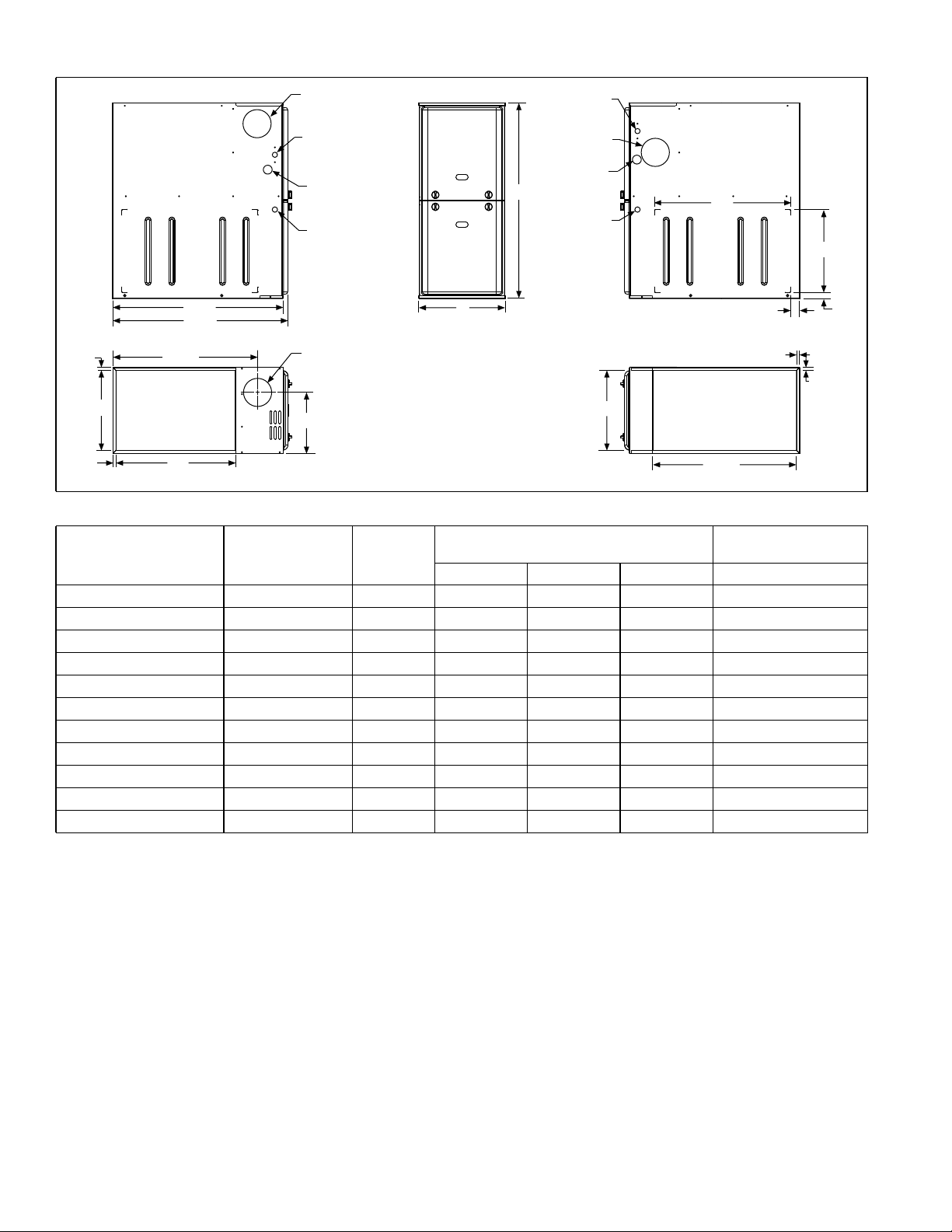
Cabinet & Duct Dimensions
Models
Nominal
CFM (m
3
/min)
Cabinet
Size
TM(8,L)E040A12MP11 1200 A 14 1/2 13 3/8 10.3 89
TM(8,L)E060A12MP11 1200 A 14 1/2 13 3/8 10.3 94
TM(8,L)E080B12MP11 1200 B 17 1/2 16 3/8 11.8 103
TM(8,L)E080C16MP11 1600 C 21 19 7/8 13.6 116
TM(8,L)E080C20MP11 2000 C 21 19 7/8 13.6 121
TM(8,L)E100B12MP11 1200 B 17 1/2 16 3/8 11.8 108
TM(8,L)E100C16MP11 1600 C 21 19 7/8 13.6 120
TM(8,L)E100C20MP11 2000 C 21 19 7/8 13.6 124
TM(8,L)E120C16MP11 1600 C 21 19 7/8 13.6 125
TM(8,L)E120C20MP11 2000 C 21 19 7/8 15.8 131
TM(8,L)E130D20MP11 2000 D 24 1/2 23 3/8 17.5 137
Cabinet Dimensions (Inches)
Operating Weights
A B C Lbs
´
´
´
$
Approximate
´
´
2 Johnson Controls Unitary Products

Ratings & Physical / Electrical Data
5597959-BTG-A-0119
Models
TM(8,L)E040A12MP11 40 32 80.0 20-50 190 1/2 6.4 11 x 8 15 8.2 1/2"
TM(8,L)E060A12MP11 60 48 80.0 30-60 190 1/2 6.4 11 x 8 15 8.2 1/2"
TM(8,L)E080B12MP11 80 64 80.0 35-65 190 1/2 6.4 11 x 8 15 8.7 1/2"
TM(8,L)E080C16MP11 80 64 80.0 30-60 190 1/2 6.4 11 x 10 15 8.7 1/2"
TM(8,L)E080C20MP11 80 64 80.0 25-55 190 1 11.5 11 x 11 20 13.8 1/2"
TM(8,L)E100B12MP11 100 80 80.0 40-70 190 1/2 6.4 11 x 8 15 8.7 1/2"
TM(8,L)E100C16MP11 100 80 80.0 40-70 190 3/4 8.8 11 x 10 15 11.1 1/2"
TM(8,L)E100C20MP11 100 80 80.0 25-55 190 1 11.5 11 x 11 20 13.8 1/2"
TM(8,L)E120C16MP11 120 96 80.0 40-70 190 3/4 8.8 11 x 10 15 11.1 1/2"
TM(8,L)E120C20MP11 120 96 80.0 35-65 190 1 11.5 11 x 11 20 13.7 1/2"
TM(8,L)E130D20MP11 130 104 80.0 35-65 190 1 11.5 11 x 11 20 13.7 1/2"
Annual Fuel Utilization Efficiency (AFUE) numbers are determined in accordance with DOE Test procedures.
Wire size and over current protection must comply with the National Electrical Code (NFPA-70-latest edition) and all local codes.
The furnace shall be installed so that the electrical components are protected from water.
Input Output
MBH MBH °F °F HP Amps
AFUE
Air Temp.
Rise
Max. Outlet
Air Temp
Blower
Blower
Size
Recommended
Fuse or Circuit
Breaker Amps
Total Unit
Amps
Gas Pipe
Connection,
NPT
HORIZONTAL SIDEWALL VENTING
For applications where vertical venting is not possible, the only
approved method of horizontal venting is the use of an auxiliary
power vent. Auxiliary power venters must be approved by CSA,
UL, or other recognized safety agencies. Follow all application
and installation details provided by the manufacturer of the
power vent.
Single side return above 1800 CFM is approved as long as
the filter velocity does not exceed filter manufacturer’s recommendation and a transition is used to allow use on a
20x25 filter.
Recommended Filter Sizes
NOTICE
FILTER PERFORMANCE
Cabinet
Size
!
CAUTION
In downflow furnace arrangement, the filter must be located
a minimum of 12” from the return air inlet of furnace.
The airflow capacity data published in the “Blower Performance” table shown represents blower performance WITHOUT
filters.
All applications of these furnaces require the use of field
installed air filters. All filter media and mounting hardware or
provisions must be field installed external to the furnace cabinet. DO NOT attempt to install any filters inside the furnace.
3
CFM (m
1. Air velocity through throwaway type filters may not exceed 300 feet per min-
2. Do not exceed 1800 CFM using a single side return and a 16x25 filter. For
/min)
1200 (34.0) A 16 x 25 14 x 25
1200 (34.0) B 16 x 25 16 x 25
1600 (45.3) C 16 x 25 20 x 25
2000 (56.6) C (2) 16 x 25 20 x 25
2000 (56.6) D (2) 16 x 25 22 x 25
ute (91.4 m/min). All velocities over this require the use of high velocity filters.
CFM greater than 1800, you may use two side returns or one side and the
bottom or one return with a transition to allow use of a 20x25 filter.
Unit Clearances to Combustibles (All dimensions in inches, and all surfaces identified with the unit in an upflow configuration)
Side
(in)
Bottom
(in)
Application Top Front Rear
Upflow 1 6 0 0 3 6 Combustible Yes Yes Yes No
Upflow B-Vent 1 3 0 0 0 1 Combustible Yes Yes Yes No
Downflow 1 6 0 0 3 6
Downflow B-Vent 1 3 0 0 0 1
Horizontal 1 6 0 0 3 6 Combustible No Yes Yes
Horizontal B-Vent 1 3 0 0 0 1 Combustible No Yes Yes
1. Special floor base or air conditioning coil required for use on combustible floor.
2. Line contact only permitted between lines formed by the intersection of the rear panel and side panel (top in horizontal position) of the furnace jacket and building
joists, studs, or framing.
Left
Side
Right
Side
Flue
Floor/
Bottom
1
1
1
1
Closet Alcove Attic
Yes Yes Yes No
Yes Yes Yes No
Contact
Line
Yes
Yes
2
2
Johnson Controls Unitary Products 3

5597959-BTG-A-0119
ACCESSORIES
Propane (LP) Conversion Kit - This accessory conversion kit
may be used to convert natural gas units for LP operation.
S1-1NP0347 - All Models except 130,000 BTU input
S1-1NP0501 - 130,000 BTU input only
LP Stainless Steel Burner Kit - This accessory conversion kit
may be used to convert existing burners to stainless steel burners for LP use only.
S1-32926889000 - All LP Models
Natural (NAT) Gas Stainless Steel Burner Kit - This acces-
sory kit may be used to replace existing burners with stainless
steel burners for NAT gas use only.
S1-32924441000 - All NAT gas Models
Side Return Filter Racks - The S1-1SR0200 Kit accommo-
dates a 1", 2", or 4" filter. The S1-1SR0402 Kit accommodates a
1" filter only.
S1-1SR0200 - All Models
S1-1SR0402 - All Models
Bottom Return Filter Racks - The S1-1BR05* series are galvanized steel filter racks. The S1-1BR06* series are pre-painted
steel filter racks to match the appearance of the furnace cabinet. The S1-1BR05* and S1-1BR06* series filter racks accommodate a 1", 2", or 4" filter.
S1-1BR0514 or S1-1BR0614 - For 14-1/2" cabinets
S1-1BR0517 or S1-1BR0617 - For 17-1/2" cabinets
S1-1BR0521 or S1-1BR0621 - For 21" cabinets
S1-1BR0524 or S1-1BR0624 - for 24-1/2" cabinets
Masonry Chimney Kit - This accessory kit allows upflow 80%
models to be vented into a tile-lined masonry chimney.
S1-1CK0604 - All 80% Non-modulating Models
Combustible Floor Base Kit - These kits are required to pre-
vent potential overheating situations when the furnaces are
installed in downflow applications directly onto combustible
flooring material. These kits are also required in any applications where the furnace is installed in a downflow configuration
without an indoor coil and where the combustible floor base kit
provides access for combustible airflow.
S1-1CB0514 - For 14-1/2" cabinets
S1-1CB0517 - For 17-1/2" cabinets
S1-1CB0521 - For 21" cabinets
S1-1CB0524 - for 24-1/2" cabinets
High Altitude Pressure Switches - For installation where the
altitude is less than 5,000 feet, it is not required that the pressure switch be changed. For altitudes above 5,000 feet, see kits
below.
S1-1PS3301 - 040, 060, 080, 120
S1-1PS3302 - 100, 130
Thermostats - Compatible thermostat controls are available
through accessory sourcing. For optimum performance, these
outdoor units are fully compatible with our residential Hx™
Touchscreen Thermostats available through Source1. For more
information, see the thermostat section of the Product Equipment Catalog.
4 Johnson Controls Unitary Products

Blower Performance CFM - Any Position (without filter)
Models Speed
0.1 0.2 0.3 0.4 0.5 0.6 0.7 0.8
High 1408 1358 1313 1275 1227 1180 1133 1088
Medium High 1195 1153 1093 1043 1005 957 904 850
TM(8,L)E040A12MP11
TM(8,L)E060A12MP11
TM(8,L)E080B12MP11
TM(8,L)E080C16MP11
TM(8,L)E080C20MP11
TM(8,L)E100B12MP11
TM(8,L)E100C16MP11
TM(8,L)E100C20MP11
TM(8,L)E120C16MP11
TM(8,L)E120C20MP11
For notes, see Page 6.
Medium 1053 1008 954 897 851 797 755 702
Medium Low 947 892 838 783 738 684 626 582
Low 649 697 682 630 575 518 471 422
High 1343 1309 1279 1238 1193 1163 1123 1075
Medium High 1149 1107 1074 1031 993 942 900 857
Medium 997 959 911 877 825 777 737 697
Medium Low 921 878 831 782 731 696 651 599
Low 838 784 742 695 648 601 551 518
High 1457 1421 1387 1358 1325 1289 1256 1220
Medium High 1336 1302 1269 1233 1198 1163 1124 1083
Medium 1118 1088 1052 1016 973 945 885 841
Medium Low 994 957 926 880 839 786 734 686
Low 811 770 725 673 625 572 521 467
High 1784 1746 1704 1660 1607 1556 1504 1466
Medium High 1444 1405 1354 1304 1252 1210 1157 1114
Medium 1253 1211 1157 1111 1064 1015 969 908
Medium Low 1083 1033 979 924 872 816 755 693
Low 902 849 787 724 659 593 538 475
High 2200 2162 2110 2061 2021 1981 1931 1970
Medium High 1980 1939 1892 1846 1804 1758 1701 1652
Medium 1734 1687 1645 1592 1547 1504 1456 1408
Medium Low 1597 1547 1504 1457 1410 1357 1310 1256
Low 1413 1362 1304 1247 1195 1148 1095 1046
High 1360 1321 1288 1259 1223 1182 1146 1105
Medium High 1197 1154 1127 1085 1046 1005 957 912
Medium 1016 981 945 899 859 805 761 710
Medium Low 916 878 839 794 743 691 643 595
Low 781 741 696 643 594 535 482 433
High 1795 1755 1715 1673 1631 1587 1533 1479
Medium High 1464 1417 1364 1325 1290 1227 1188 1138
Medium 1217 1171 1120 1072 1021 978 924 869
Medium Low 1062 1011 956 910 858 801 738 669
Low 905 847 784 732 668 601 540 465
High 2219 2179 2136 2095 2044 2001 1952 1912
Medium High 1994 1951 1911 1872 1820 1774 1733 1678
Medium 1727 1687 1648 1595 1558 1502 1456 1406
Medium Low 1618 1574 1528 1480 1432 1383 1337 1288
Low 1410 1364 1316 1255 1206 1164 1109 1042
High 1765 1721 1684 1635 1606 1542 1503 1442
Medium High 1429 1384 1340 1292 1256 1209 1164 1114
Medium 1207 1169 1119 1077 1028 977 930 888
Medium Low 1055 1018 955 907 862 810 761 705
Low 885 834 783 733 675 618 544 500
High 2235 2199 2148 2108 2066 2034 1984 1932
Medium High 1960 1901 1860 1819 1776 1723 1682 1642
Medium 1693 1640 1593 1557 1504 1455 1413 1365
Medium Low 1580 1533 1488 1444 1394 1342 1296 1244
Low 1417 1362 1313 1269 1223 1169 1120 1079
Airflow Data (SCFM)
Ext. Static Pressure (in. H2O)
1, 2
5597959-BTG-A-0119
Johnson Controls Unitary Products 5

Blower Performance CFM - Any Position (without filter) (Continued)
Models Speed
0.1 0.2 0.3 0.4 0.5 0.6 0.7 0.8
High 2229 2182 2133 2088 2047 1996 1946 1893
TM(8,L)E130D20MP11
NOTES:
1. Airflow expressed in standard cubic feet per minute (SCFM).
2. Motor voltage at 115 V.
3. Not all speeds are recommended for use as heating speeds.
Medium High 2009 1968 1925 1881 1829 1778 1737 1679
Medium 1818 1765 1729 1675 1616 1580 1540 1480
Medium Low 1569 1520 1472 1427 1376 1329 1281 1237
Low 1448 1394 1341 1275 1221 1183 1131 1085
Airflow Data (SCFM)
Ext. Static Pressure (in. H2O)
1, 2
Subject to change without notice. Published in U.S.A. 5597959-BTG-A-0119
Copyright © 2019 by Johnson Controls, Inc. All rights reserved. Supersedes: Nothing
York International Corp.
5005 York Drive
Norman, OK 73069
 Loading...