

,.,
'-"f"oI:tI
WARNING
,.. SAFETY WARNING: Failure to obey a safety warning may result In Injury to you or
T to others.
INSTRUCTIONS FOR THE MODEL 1400
~ CAUTION-ALWAYS KEEP THE
T MUZZLE POINTED IN A SAFE DIREC-
TION. Prior to using live ammunition, famil-
iarize yourself thoroughly with these operat-
ing instructions. Get accustomed to the feel
of your new gun
to operate the action, to pull the trigger and
above all, KNOW THE LOCATION OF THE
SAFETY which, on this shotgun, is on the
trigger guard. The safety is placed in the "on"
position when pushed from left to right until
the red "warning" ring disappears. When the
red ring is visible on the left side of the
safety, it is in the "off" position, and the gun
is ready to fire. The safety can only be placed
in the "on" position when the hammer is
cocked.
~;'~'N~~~KEEP YOUR FINGERS CLEAR OF
T THE EJECTION PORT. The breech
bolt on the Model 1400, like most all auto-
matic actions, is under strong spring tension
and closes very swiftly. If closed on a finger,
it will cause a painful injury.
~;,~...~~~ IMPORTANT- CLEAN THE INSIDE
.
OF THE BARREL AND CHAMBER TO
T
REMOVE ALL GREASE AND OTHER POS-
SIBLE OBSTRUCTIONS BEFORE FIRING
YOUR GUN.
HOW TO CARE FOR YOUR MODEL 1400-
Protect your gun with good gun care prod-
ucts. Give it regular attention, and it will pro-
vide you with many years of shooting fun.
REMEMBER
sure all exposed metal surfaces are coated
with a film of oil. After being subjected to
damp weather thoroughly wipe out the bore
and wipe off the metal surfaces. Then apply
a new film of oil. If exposed to a soaking rain,
snow or salt spray a more thorough cleaning
and oiling may be necessary, requiring re-
moval of the trigger guard and breech bolt
assemblies.
~l~"'~~~Between seasons, apply a coat of
fabric or material which will absorb the lub-
from the receiver do not allow the breech
grease to the bore and metal parts and
T
store in a dry place. DO NOT PLUG THE
BARREL, or store in a case that is made of a
ricant from the gun.
IMPORTANT -
bolt to close unrestricted. Repeated, full
force, closing of the bolt with the barrel off
will abuse the action parts. Instead, grasp the
cocking handle before pushing the action re-
lease button and permit the action to close
slowly.
- know the forces required
RUST IS NEGLECT
-
With the barrel removed
- Make
TO ASSEMBLE
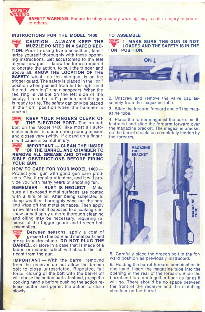
~;,~...~~~1. MAKE SURE THE GUN IS NOT
T LOADED AND THE SAFETY IS IN THE
"ON" POSITION.
ON
-i
;\-
2. Unscrew and remove the valve cap as-
sembly from the magazine tube.
3. Slide the forearm forward and off the mag-
azine tube.
4. Place the forearm against the barrel as il-
lustrated and slide the forearm forward over
the magazine bracket. The magazine bracket
on the barrel should be completely hidden by
the forearm.
MAGAZINE
TUBE
BRACKET
/
.
"
~
:/
I
5. Carefully place the breech bolt in the for-
ward position as previously instructed.
6. Holding the barrel-forearm combination in
one hand, insert the magazine tube into the
opening In the rear of 1he forearm. Slide the
barrel and forearm together back as far as it
will go. There should be no space between
the front of the receiver and the matching
shoulder on the barrel.
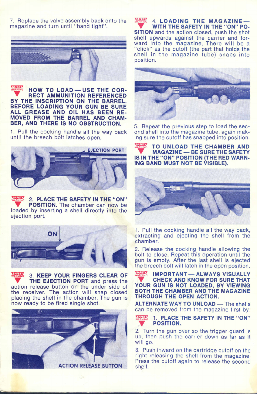
7. Replace the valve assembly back onto the
magazine and turn until "hand tight".
~
~l~"'~~~ HOW TO LOAD
T RECT AMMUNITION REFERENCED
BY THE INSCRIPTION ON THE BARREL.
BEFORE LOADING YOUR GUN BE SURE
ALL GREASE AND OIL HAS BEEN RE-
MOVED FROM THE BARREL AND CHAM-
BER, AND THERE IS NO OBSTRUCTION.
1. Pull the cocking handle all the way back
until the breech bolt latches open.
USE THE COR-
-
~l~"'~~~ 4. LOADING THE MAGAZINE-
T WITH THE SAFETY IN THE "ON" PO-
SITION and the action closed, push the shot
shell upwards against the carrier and for-
ward into the magazine. There will be a
"click" as the cutoff (the part that holds the
shell in the magazine tube) snaps into
position.
5. Repeat the previous step to load the sec-
ond shell into the magazine tube, again mak-
ing sure the cutoff has snapped into position.
~ TO UNLOAD THE CHAMBER AND
T MAGAZINE
IS IN THE "ON" POSITION (THE RED WARN-
ING BAND MUST NOT BE VISIBLE).
BE SURE THE SAFETY
-
~l~'N~~~2. PLACE THE SAFETY IN THE "ON"
T POSITION. The chamber can now be
loaded by inserting a shell directly into the
ejection port.
-
--=l -
~;\-
~l~'N~~~ 3. KEEP YOUR FINGERS CLEAR OF
T THE EJECTION PORT and press the
action release button on the under side of
the receiver. The action will snap closed
placing the shell in the chamber. The gun is
now ready to be fired single shot.
1. Pull the cocking handle all the way back,
extracting and ejecting the shell from the
chamber.
2. Release the cocking handle allowing the
bolt to close. Repeat this operation until the
gun is empty. After the last shell is ejected
the breech bolt will latch in the open position.
~ IMPORTANT-ALWAYS VISUALLY
T CHECK AND KNOWFOR SURE THAT
YOUR GUN IS NOT LOADED, BY VIEWING
BOTH THE CHAMBER AND THE MAGAZINE
THROUGH THE OPEN ACTION.
ALTERNATE WAY TO UNLOAD -
can be removed from the magazine first by:
~~~'N~~~ 1. PLACE THE SAFETY IN THE "ON"
T POSITION.
2. Turn the gun over so the trigger guard is
up, then push the carrier down as far as it
will go.
3. Push inward on the cartridge cutoff on the
right releasing the shell from the magazine.
Press the cutoff again to release the second
sh!3l1.
The shells
.

--
:;1~'N~~~ 4. WITH THE SAFETY STILL IN THE
~ "ON" POSITION, pull the cocking
handle all the way back to remove the shell
from the chamber.
~ HOW TO FIRE
~ "ON" load your gun as previously in-
structed. When ready to shoot, firmly shoul-
der your gun and push the safety to the "off"
position exposing the red warning ring. Aim,
and when on target pull the trigger to fire.
- WITH THE SAFETY
ON
~
~. I
~
~ When fired, the Model 1400's auto-
'Y matic action will eject the fired shell,
cock the hammer and on closing will place
a new shell from the magazine into the cham-
ber ready for the next shot. When the last
shell in the gun is fired the action will remain
open and convenient for reloading. WHEN
THROUGH FIRING ALWAYS PUT THE
SAFETY IN THE "ON" POSITION.
~ TO TAKE DOWN
~ TION AND MAKE SURE THE GUN IS
NOT LOADED.
2. Close the action and PLACE THE SAFETY
IN THE "ON" POSITION.
3. Unscrew and remove the valve assembly
from the magazine.
I
--------
1. OPEN THE AC-
-
"
4. To remove the barrel, slide the barrel and
forearm forward as a single unit until the
forearm clears the end of the magazine tube.
~
5. Remove the forearm from the barrel by
sliding the forearm to the rear and lifting free
of the magazine bracket on the barrel.
TO REMOVE THE BREECH BOLT
1. Remove the barrel and forearm as ex-
plained earlier.
:;~~...~~~2. BE SURE GUN IS UNLOADED.
~ CLOSE ACTION, PUSH SAFETY TO
"ON" POSITION, turn gun until trigger guard
is up, and push out trigger guard pin from left.

3. Lift trigger group out of receiver by pull-
ing on trigger guard.
4. Do not pull trigger after disassembly.
5. Remove the ejector (the flat spring like
piece that fits along the inside wall of the re-
ceiver) by bending the rear section of the
ejector inward just enough to disengage the
small retaining pin in the side of the receiver.
Pull the ejector out the barrel hole in the front
of the receiver.
:;;~'N~~~ 6. THE PISTON IS UNDER SPRING
T TENSION. WITH THE GUN UPRIGHT
AND THE MAGAZINE POINTED IN A SAFE
DIRECTION, insert a screw driver or a suit-
able rod into the coils of the closing spring
at the forward end of the slot in the top of the
magazine tube. Draw back on the tool reliev-
ing the tension from the piston. While holding
the spring compressed, remove the piston
pin that connects the slide arms to the piston.
Place.your free hand over the end of the mag-
azine tube, then remove the tool from the
coils and withdraw the piston and closing
spring from the end of the tube. Disconnect
and remove the slide arms from the receiver.
7. Remove the cocking handle bridge screw
(the screw in the underside of the bolt as-
sembly). The firing pin is under spring ten-
sion and will snap out of the rear of the
breech bolt when the cocking handle bridge
is lifted from the breech bolt slide. Remove
the firing pin and spring.
8. Slide the breech bolt with the cocking
handle to the rear of the receiver. Grasp the
cocking handle and by tipping and manipu-
lating the handle, remove the cocking handre
bridge out through the ejection port in the
receiver. Now the breech bolt assembly may
be lifted out or slid out the front of the re-
ceiver. For routine cleaning no further dis-
mantling is necessary.
TO REINSTALL THE BREECH BOLT
ASSEMBLY
1. Insert the breech bolt assembly through
the front of the receiver and move the as-
sembly to the rear of the receiver. Holding
the cocking handle, insert the bridge section
in through the ejection port. Then by tipping
and manipulating the cocking handle place
the bridge into position on the breech bolt
slide. Slide the assembly forward in the re-
ceiver, then lift up the rear of the cocking
handle bridge and insert the firing pin with
the firing pin spring into the back of the
breech bolt. When the firing pin is in posi-
tion lower the rear of the bridge so the tail of
the bridge enters the groove in the firing pin,
to hold it in place. Next, install the bridge
screw, securing the bridge to the bolt slide.
2. Insert the slide arms into the receiver and
connect the arms with the matching notches
in the cocking handle bridge.
3. Place the end of the closing spring having
the smaller coils into the end of the magazine
tube. Place a screw driver or a suitable tool
into coils of the closing spring through the
forward end of the slot in the tube and be-
tween the slide arms. Position the piston into
the tube so the 3 holes in the piston are up
and with the larger single hole to the rear.
0;~'N~~~WITH THE MAGAZINE POINTED IN A
T SAFE DIRECTION, draw back on the
tool, compressing the closing spring. Align
the larger hole in the piston with the hole in
the forward end of the slide arms. Insert the
piston pin through the hole in the slide arm
and into the piston. Then remove the tool re-
leasing the spring.
HOW TO INSTALL THE EJECTOR
the bowed side toward the breech bolt, slide
the flat end of the ejector through the barrel
hole in the receiver and down between the
breech bolt slide and the left inside wall of
the receiver. Bend the rear of the ejector
slightly inward and connect the ejector with
the retaining pin in the side of the receiver.
EJECTOR
- With

~ TO REINSTAll THE TRIGGER
GUARD ASSEMBLY
1. With the hammer cocked and the SAFETY
ON place the forward end of the guard as-
sembly into the receiver. Locate the slide
HAMMER
'>I
~
supports (the flat bars on the sides of the
assembly) into the mating notches in the
throat of the magazine.
2. Pivot the rear of the guard into the re-
ceiver and insert the trigger guard pin into
the right side of the receiver.
INSTAllATION AND REMOVAL OF
THE WINCHOKE
REMOVAL - To remove the WINCHOKE
from the barrel, insert the projection on the
special WINCHOKE tool into the hole on the
knurled portion of WINCHOKE tube and turn
counterclockwise.
INSTAllATION
be snugly fitted, but not over-tightened for
ease of removal later and possible damage to
the barrel. The WINCHOKE has a right hand
thread and with the aid of the special tool
simply screw the tube of your choice into the
muzzle of the barrel.
- The WINCHOKE should
TEN COMMANDMENTS OF
FIREARMS SAFETY
A good hunter is a safe hunter. He knows there is
no place for horseplay in hunting. He learns and
obeys the commandments of firearms safety and
insists that his companions know and follow the~,
too.
Every hunter
outdoorsman - should review these command-
ments before each hunting season to be sure that
his gun handling, both at home and in the field,
sets a good example for others.
1. Treat every gun with the respect due a loaded
gun.
2. Be sure of your target before you pull the
trigger.
3. Always be sure that the barrel and action are
clear of obstruction.
4. Never point your gun at anything you do not
want to shoot.
5. Never leave your gun unattended unless you
unload it first.
6. Avoid alcoholic beverages both before and dur-
ing shooting.
7. Never climb a tree or cross a fence with a
loaded gun.
8. Never shoot at a hard, flat surface or the sur-
face of water. Make sure you have a safe backstop.
9. Carry only empty guns, taken down or with the
action open, into your camp, car or home.
10. Store guns and ammunition separately, be-
yond the reach of children.
whether novice or experienced
-
U1ili7
WARNING
....
Form No. 4049-3
It is recommended that SHOOTING GLASSES be worn at all times and
that EAR PROTECTION be utilized where practical.
1'YINCH£.fl'£ll-;;~.
275 WINCHESTER AVENUE, NEW HAVEN, CONNECTICUT 06504

60 -:A
50- filii"'"
2
~
61-"
{I'
)?'
"
27 \.,'~
3
\ \'
28
,~~'"
\
.\\",\\,\\"
26
Y'
!
19
i
24
~~A1-~,"
33 I
.
I 1
11.
",-;t:;...,
16-\ '-56
~
~~49
~~
~:::::,
J~
20-
~
21-
/
MODEL 1400 NOMENCLATURE
Parts may be ordered directly from Winchester Product Service Dept. Please specify part num-
ber, part name, serial #, gauge, chamber length, and grade (Le., Field, V.A., etc.).
Reference
Number
Barrel
1
2
Breech Bolt
3
Breech Bolt Slide
4
Buttstock
5
Buttstock Bolt
Buttstock Bolt Washer
6
Buttplate
7
Buttplate Screw (2 Required)
8
Cam Pin
9
10
Carrier Assembly
Carrier Plunger
11
Carrier Release
12
Carrier Release Pin
13
14
Carrier Release Spring
Carrier Release Spring Retainer
15
16
Carrier Spring 35
Carrier Support Spring 36
17
Cocking Handle Bridge 37
18
Cocking Handle Bridge Retaining 38
19
Screw 39
20 Disconnector Assembly 40
"Sold for factory installation only-return complete firearm.
tNot sold to consumers. Installation must be made by a gunsmith. Orders from dealers and distributors will be accepted on the understanding that the parts will be
fitted by a gunsmith.
Part Reference Part Reference
Description Number Description Number
21 Disconnector Spring 41
22 Ejector 42
23 Ejector Retaining Pin 43
24 Extractor 44
25 Extractor Spring 45
26 Firing Pin "46
27 Firing Pin Collar 47
28 Firing Pin Spring 48
29 Forearm 49
30 Hammer 50
31 Hammer Housing 51
32 Hammer Pin 52
33 Hammer Spring 53
34 Hammer Spring Support t54
(2 Required) 55
Magazine Cap Retainer & Spring 56
Magazine Damper Spring t57
Magazine Follower 58
Magazine Tube 59
Magazine Spring 60
Magazine Throat 61
Part
Description
Pistol Grip Cap
Pistol Grip Cap Insert
Pistol Grip Cap Screw
Piston
Piston Pin
Receiver
Return Spring
Safety
Sear Assembly
Sight
- Front
Slide Arm
Slide Support W/Cutoff-Left Hand
Slide Support W /Cutoff-Right Hand
Trigger Assembly
Trigger Guard
Trigger Guard Pin
Trigger Pin
Trigger Stop Pin Screw
Valve Cap Assembly
Winchoke Tube
Winchoke Spanner Wrench
 Loading...