

Winbond Electronics W91580C, W91580B, W91580A, W91580 Datasheet
W91580 SERIES
24-MEMORY TONE/PULSE SWITCHABLE DIALER
WITH HANDFREE AND HOLD FUNCTIONS
GENERAL DESCRIPTION
The W91580 series dialers are Si-gate CMOS IC tone/pulse switchable dialers containing a 24channel automatic dialing memory, including a 16-digit × 3 emergency dialing memory, a 16-digit ×
20 channel repertory memory that provides one-touch and three-touch dialing, and a 32-digit mercury
memory. These dialers also provide flash, clear, hold, and one-key redial functions.
FEATURES
• DTMF/Pulse switchable dialer
• 31/32-digit LNB (last number buffer) memory (tone/pulse mode)
• 31/32-digit mercury memory (tone/pulse mode)
• 15/16-digit × 3 one-touch direct repertory memory (tone/pulse mode)
• 15/16-digit × 20 direct or indirect repertory memory (tone/pulse mode)
• Uses 9 × 5 keyboard
• Flash time: 98 mS, 305 mS, or 600 mS (selectable by keypad option)
• Pause time: 3.6 sec.
• Pause and P→T (pulse-to-tone) can be stored as a digit in memory
• Minimum tone output duration: 100 mS
• Minimum intertone pause: 100 mS
• On-chip power-on reset
• Uses 3.579545 MHz crystal or ceramic resonator
• Packaged in 22, 24, or 28-pin plastic DIP
• The different dialers in the W91580 series are shown in the following table:
TYPE NO. PULSE
(ppS)
MEMORY MERCURY
MEMORY
HOLD HANDFREE PACKAGE
W91580 10 20 - - - 22
W91580A 10 20 - - Yes 24
W91580B 10/20 24 Yes Yes Yes 28
W91580C 10/20 24 Save Yes Yes 28
Publication Release Date: Auguest 1995
- 1 - Revision A3
PIN CONFIGURATIONS
W91580
W91580A
W91580B/C
XT
MUTE
MUTE
W91580 SERIES
C2
T/P MUTE
C3
C4
C5
C6C76
C8
KT
V
SS
XT
XT
HFI
T/P MUTE
C2
C3
C4
C5
C6C76
V
SS
XT
XT
1
2
3
4
5 18
7
8
9 14
10
11 12
1
R5
22C1
R4
21
20
R3
R2
19
R1
NC
17
V
16
DD
15
MODE
DTMF
13
DP/C9
HKS
T/P MUTE
C2
C3
C4
C5
C6C76
V
SS
XT
XT
HFI
2
3
4
5 20
7
8
9 16
10
11
12
R5
24C1
R4
23
22
R3
R2
21
R1
NC
19
V
18
DD
17
MODE
DTMF
15
DP/C9
HKS
14
13
HFO
PIN DESCRIPTION
SYMBOL 22-PIN 24-PIN 28-PIN I/O FUNCTION
1
2
3
4
5 24
7
8
9 20
10
11
12 17
14 1516HFO
R5
28C1
R4
27
26
R3
R2
25
R1
HPM MUTE
23
NC
22
DRS
21
V
MODE
19
DTMF
18
DP/C9
HKS13
DD
Column-
Row
Inputs
XT,
T/P
HPM
MUTE
1−7
&
18−22
1−7
&
20−24
1−8
&
24−28
I The keyboard input may be used with either the
standard 9 × 5 keyboard or an inexpensive
single contact (form A) keyboard. Electronic
input from a µC can also be used.
A valid key entry is defined by a single row
being connected to a single column.
9, 10 9, 10 11, 12 I, O A built-in inverter provides oscillation with an
inexpensive 3.579545 MHz crystal or ceramic
resonator.
11 11 13 O
The T/P
is a conventional CMOS
N-channel open drain output.
The output transistor is switched on during pulse
and tone mode dialing sequence and flash
break. Otherwise, it is switched off.
- - 23 O The HPM MUTE is a conventional inverter
output. During pulse dialing, flash, hold, and
mercury mute functions, this pin will output an
active high. It remains in a low state at all other
times.
- 2 -
W91580 SERIES
HKS
HKS
HKS
HKS
DP/C9
Pin Description, continued
SYMBOL 22-PIN 24-PIN 28-PIN I/O FUNCTION
MODE 15 17 19 I Pulling mode pin to VSS places the dialer in tone
mode.
Pulling mode pin to VDD places the dialer in pulse
mode (10 ppS, M/B = 2:3).
Leaving mode pin floating places the dialer in
pulse mode (10 ppS, M/B = 1:2).
12 14 16 I Hook switch input.
= 1: On-hook state. Chip in sleep mode, no
operation.
= 0: Off-hook state. Chip enabled for normal
operation.
pin is pulled to VDD by internal resistor.
13 15 17 O N-channel open drain dialing pulse output
(see Figure 1).
Flash key causes DP to go active when in pulse
mode and tone mode.
NC 17 19 22 - No connection.
DTMF 14 16 18 O In pulse mode, remains in low state at all times. In
tone mode, outputs a dual or single tone. Detailed
timing diagram for tone mode is shown in Figure 2.
OUTPUT FREQUENCY
Specified Actual Error %
R1
R2
R3
R4
C1
C2
C3
697
770
852
941
1209
1336
1477
699
766
848
948
1216
1332
1472
+0.28
-0.52
-0.47
+0.74
+0.57
-0.30
-0.34
VDD, VSS 16, 8 18, 8 20, 10 I Power input pins.
Publication Release Date: Auguest 1995
- 3 - Revision A3
W91580 SERIES
HFI
HFI
HFI
HFI
HFI
Pin Description, continued
SYMBOL 22-PIN 24-PIN 28-PIN I/O FUNCTION
, HFO
- 12, 13 14, 15 I, O
Handfree control pins. A low pulse on the
input pin toggles the handfree control state. The
status of the handfree control state is described by
the following table:
CURRENT STATE
Hook SW.
-
On Hook
Off Hook
On Hook
Off Hook
Off Hook
HFO
Low
High
High
-
Low
High
Off Hook
On Hook
On Hook
Input
HFI
NEXT STATE
HFO
High
Low
Low
Low
Low
High
Dialing
Yes
No
Yes
Yes
No
Yes
pin is pulled to VDD by internal resistor.
KT - - 9 O Keytone signal output. A keytone will be generated
whenever a valid key is pressed. Frequency is 600
Hz and duration is 35 mS.
DRS - - 21 I Dial rate selection.
This pin is pulled to VDD by an internal resistor.
- 4 -
DRS
1
0
MODE
PIN
V
DD
Floating
V
SS
V
DD
Floating
V
SS
TONE/PULSE
Pulse
Pulse
Tone
Pulse
Pulse
Tone
DIAL
RATE
10 ppS
10 ppS
10 ppS
20 ppS
M/B
2:3
1:2
1:2
1:2
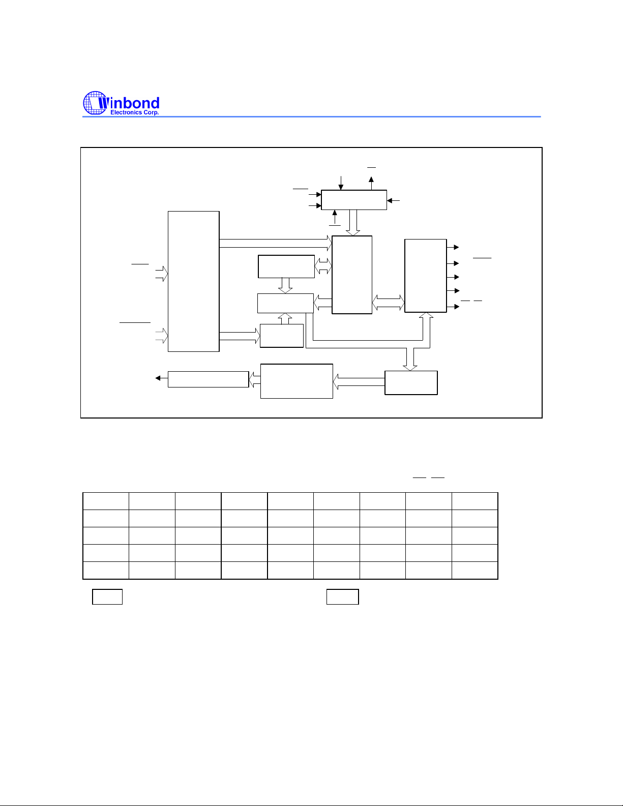
BLOCK DIAGRAM
C1C2C3C4C5C6C7
DP/C9
C8
W91580 SERIES
ROW
(R1 to R5)
COLUMN
(C1 to C8)
DTMF
KEYBOARD
INTERFACE
D/A CONVERTER
FUNCTIONAL DESCRIPTION
Keyboard Operation
HKS
MODE
READ/WRITE
COUNTER
RAM
LOCATION
LATCH
ROW & COLUMN
PROGRAMMABLE
COUNTER
XT
SYSTEM CLOCK
GENERATOR
HFI
CONTROL
XT
LOGIC
DRS
PULSE
CONTROL
LOGIC
DATA LATCH
& DECODER
KT
T/P MUTE
HPM MUTE
HFO
DP/C9
1 2 3 S M00 M05 M10 M15 EM1 R1
4 5 6 MEMO M01 M06 M11 M16 EM2 R2
7 8 9 CLR M02 M07 M12 M17 EM3 R3
*/T 0 # R/P M03 M08 M13 M18 H R4
F1 F2 F3 R M04 M09 M14 M19 *MER R5
* MER is for W91580B only; Fin W91580C this key performs Save function.
Publication Release Date: Auguest 1995
- 5 - Revision A3
• S: Store function key
DP/C9
HFI
HFI
HFI
HFI
HFI
HFI
• F1, F2, F3: Flash keys
• R: One-key redial
• H: Hold function key
W91580 SERIES
•
• M0j: Direct or indirect (MEMO + M0j = M1j) repertory memory
• M1j: Direct repertory dialing
• EMi: One-touch memory for emergency call
• */T: * & P→T
• CLR: Clear key
• R/P: Redial and pause function key
• MER: One-touch memory for mercury code dialing
• MEMO: Indirect repertory dialing function key
Note: Dn = 0 to 9, *, #, Mij = M00 to M19 (i = 0, 1; j = 0 to 9).
: This key is connected to pin DP/C9 via a bipolar switching transistor and a diode.
Normal Dialing
OFF HOOK (or ON HOOK &
1. D1, D2, ..., Dn will be dialed out.
2. Dialing length is unlimited, but redial is inhibited if length exceeds 32 digits.
), D1 , D2
, …,
Redialing
1. OFF HOOK , D1 , D2
(or ON HOOK &
, …,
Dn BUSY, Come ON HOOK , OFF HOOK
), R/P
Dn
or ON HOOK &
, D1 , D2
, …,
Dn , BUSY,
Come
, R/P
The R/P key can execute the redial function only as the first key-in after off-hook; otherwise, it will
execute the pause function.
2. OFF HOOK (or ON HOOK &
), D1 , D2
, …,
Dn , R
a. The one-key redial function timing diagram is shown in Figure 4.
b. If dialing
D1 to Dn is completed, pressing the R key will cause the pulse output
of
pin to go low for 2.2 seconds. Break time and a 600 mS pause will automatically be added.
c. If the R key is pressed before the pulses for the number dialed out are completed, it will be
ignored.
- 6 -
 Loading...