

Winbond Electronics W90P710CD, W90P710 Datasheet

W90P710CD/W90P710CDG
32-BIT ARM7TDMI-BASED MCU
W90P710CD/W90P710CDG
16/32-bit ARM microcontroller
Product Data Sheet
Publication Release Date: September 19, 2006
- 1 - Revision B2
W90P710CD/W90P710CDG
Revision History
REVISION DATE COMMENTS
A 2005/12/02 Draft
A.1 2005/12/21 Modify the register definition
A.2 2006/01/17 Modify SD description
Update LCD C version design spec.
A.3 2006/07/07
B 2006/07/26
Update Smartcard C version design spec.
Add RTC 32.768K clock measurment apllication note.
Add RTC application note.
Change EBI SDRAM control register SDCONFx[13] AUTOPR
definition.
Modify LCD register map section 7.2.2
Change 2 to 1 slave/device select lines
Change SDIO to SD
Add Electrical specification
SDO change to SD page 11
SDIO change to SD page 33
“W99P710” change to “W90P710” page 245
B1 2006/08/08
B2 2006/09/19 Delete section 6
Delete “it is same as the UART of W99740” page 333
Delete “it is same as the UART of W99702” page 332
Delete “note” page 337,338
ADD USB WakeUp control bit
Update table 5.2
- 2 -

W90P710CD/W90P710CDG
Table of Contents-
1. GENERAL DESCRIPTION ......................................................................................................... 6
2. FEATURES ................................................................................................................................. 6
3. PIN DIAGRAM .......................................................................................................................... 13
4. PIN ASSIGNMENT ................................................................................................................... 14
5. PIN DESCRIPTION................................................................................................................... 20
6. FUNCTIONAL DESCRIPTION ................................................................................................. 33
6.1 ARM7TDMI CPU CORE ............................................................................................... 33
6.2 System Manager........................................................................................................... 34
6.2.1 Overview ......................................................................................................................34
6.2.2 System Memory Map....................................................................................................34
6.2.3 Address Bus Generation ..............................................................................................37
6.2.4 Data Bus Connection with External Memory ................................................................37
6.2.5 Bus Arbitration..............................................................................................................46
6.2.6 Power management .....................................................................................................47
6.2.7 Power-On Setting .........................................................................................................49
6.2.8 System Manager Control Registers Map......................................................................50
6.3 External Bus Interface .................................................................................................. 64
6.3.1 EBI Overview................................................................................................................64
6.3.2 SDRAM Controller ........................................................................................................64
6.3.3 EBI Control Registers Map ........................................................................................... 68
6.4 Cache Controller........................................................................................................... 86
6.4.1 On-Chip RAM ............................................................................................................... 86
6.4.2 Non-Cacheable Area .................................................................................................... 86
6.4.3 Instruction Cache..........................................................................................................87
6.4.4 Data Cache ..................................................................................................................89
6.4.5 Write Buffer ..................................................................................................................91
6.4.6 Cache Control Registers Map.......................................................................................91
6.5 Ethernet MAC Controller............................................................................................... 97
6.5.1 EMC Functional Description ......................................................................................... 98
6.5.2 EMC Register Mapping ..............................................................................................108
6.6 GDMA Controller ........................................................................................................ 161
6.6.1 GDMA Functional Description ....................................................................................161
6.6.2 GDMA Register Map ..................................................................................................162
6.7 USB Host Controller ................................................................................................... 171
6.7.1 USB Host Functional Description ...............................................................................171
6.7.2 USB Host Controller Registers Map ...........................................................................172
6.7.3 HCCA .........................................................................................................................194
6.7.4 Endpoint Descriptor ....................................................................................................194
6.7.5 Transfer Descriptor..................................................................................................... 194
6.8 USB Device Controller................................................................................................ 194
Publication Release Date: September 19, 2006
- 3 - Revision B2

W90P710CD/W90P710CDG
6.8.1 USB Endpoints ...........................................................................................................195
6.8.2 Standard device request.............................................................................................195
6.8.3 USB Device Register Description ...............................................................................195
6.9 SD Host Controller...................................................................................................... 234
6.9.1 Functional Description ................................................................................................234
6.9.2 Register Mapping .......................................................................................................236
6.9.3 SD Register Description .............................................................................................237
6.10 LCD Controller ............................................................................................................ 253
6.10.1 Main Features ............................................................................................................253
6.10.2 LCD Register MAP .....................................................................................................254
6.10.3 LCD Special Register Description ..............................................................................256
6.11 Audio Controller .......................................................................................................... 307
6.11.1 IIS Interface ................................................................................................................307
6.11.2 AC97 Interface ...........................................................................................................308
6.11.3 Audio Controller Register Map....................................................................................311
6.12 Universal Asynchronous Receiver/Transmitter Controller ......................................... 330
6.12.1 UART0........................................................................................................................332
6.12.2 UART1........................................................................................................................332
6.12.3 UART2........................................................................................................................334
6.12.4 UART3........................................................................................................................336
6.12.5 General UART Controller ...........................................................................................337
6.12.6 High speed UART Controller ......................................................................................350
6.13 Timer/Watchdog Controller......................................................................................... 364
6.13.1 General Timer Controller ............................................................................................ 364
6.13.2 Watchdog Timer .........................................................................................................364
6.13.3 Timer Control Registers Map...................................................................................... 364
6.14 Advanced Interrupt Controller..................................................................................... 372
6.14.1 Interrupt Sources........................................................................................................373
6.14.2 AIC Registers Map .....................................................................................................376
6.15 General-Purpose Input/Output ................................................................................... 389
6.15.1 GPIO Control Registers Map......................................................................................392
6.15.2 GPIO Register Description .........................................................................................393
6.16 Real Time Clock ......................................................................................................... 424
6.16.1 RTC Register Map...................................................................................................... 426
6.16.2 RTC Application Note ................................................................................................. 439
6.17 Smart Card Host Interface .......................................................................................... 440
6.17.1 Register Mapping .......................................................................................................440
6.17.2 Register Description ...................................................................................................442
6.17.3 Functional description.................................................................................................468
6.18 I2C Interface ............................................................................................................... 471
6.18.1 I2C Protocol ................................................................................................................472
6.18.2 I2C Serial Interface Control Registers Map ................................................................475
- 4 -

W90P710CD/W90P710CDG
Universal Serial Interface............................................................................................ 483
6.19
6.19.1 USI Timing Diagram ...................................................................................................483
6.19.2 USI Registers Map .....................................................................................................484
6.20 PWM ........................................................................................................................... 491
6.20.1 PWM double buffering and reload automatically ........................................................491
6.20.2 Modulate Duty Ratio...................................................................................................492
6.20.3 Dead Zone Generator.................................................................................................492
6.20.4 PWM Timer Start procedure.......................................................................................493
6.20.5 PWM Timer Stop procedure ....................................................................................... 493
6.20.6 PWM Register Map ....................................................................................................494
6.21 Keypad Interface......................................................................................................... 502
6.21.1 KeyPad Interface Register Map.................................................................................. 503
6.21.2 Register Description ...................................................................................................504
6.22 PS2 Host Interface Controller..................................................................................... 511
6.22.1 PS2 Host Controller Interface Register Map...............................................................512
6.22.2 Register Description ...................................................................................................512
7. ELECTRICAL SPECIFICATIONS........................................................................................... 516
7.1 Absolute Maximum Ratings ........................................................................................ 516
7.2 DC Specifications ....................................................................................................... 516
7.2.1 Digital DC Characteristics...........................................................................................516
7.2.2 USB Transceiver DC Characteristics..........................................................................518
7.3 AC Specifications........................................................................................................ 518
7.3.1 EBI/SDRAM Interface AC Characteristics ..................................................................518
7.3.2 EBI/(ROM/SRAM/External I/O) AC Characteristics .................................................... 519
7.3.3 USB Transceiver AC Characteristics.......................................................................... 520
7.3.4 EMC RMII AC Characteristics ....................................................................................521
7.3.5 LCD Interface AC Characteristics............................................................................... 523
7.3.6 SD Interface AC Characteristics.................................................................................524
7.3.7 AC97/I2S Interface AC Characteristics.......................................................................525
7.3.8 Smart Card Interface AC Characteristics....................................................................527
7.3.9 I2C Interface AC Characteristics ................................................................................528
7.3.10 USI Interface AC Characteristics................................................................................529
7.3.11 PS2 Interface AC Characteristics ...............................................................................531
8. ORDERING INFORMATION .................................................................................................. 532
9. PACKAGE SPECIFICATIONS................................................................................................ 533
10. APPENDIX A: W90P710 REGISTERS MAPPING TABLE..................................................... 534
Publication Release Date: September 19, 2006
- 5 - Revision B2

W90P710CD/W90P710CDG
1. GENERAL DESCRIPTION
The W90P710 is built around an outstanding CPU core, the 16/32 ARM7TDMI RISC processor which
designed by Advanced RISC Machines, Ltd. It offers 4K-byte I-cache/SRAM and 4K-byte Dcache/SRAM, is a low power, general purpose integrated circuits. Its simple, elegant, and fully static
design is particularly suitable for cost sensitive and power sensitive applications.
One 10/100 Mb MAC of Ethernet controller is built-in to reduce total system cost. A LCD controller is
also built-in to support TFT and low cost STN LCD modules.
With one USB 1.1 host controller, one USB 1.1 device controller, two smart card host controller, four
independent UARTs, one Watchdog timer, up to 71 programmable I/O ports, PS/2 keyboard controller
and an advanced interrupt controller, the W90P710 is particularly suitable for point-of-sale (POS),
access control and data collector.
The W90P710 also provides one AC97/I²S controller, one SD host controller, one 2-Channel GDMA,
two 24-bit timers with 8-bit pre-scale, The external bus interface (EBI) controller provides for SDRAM,
ROM/SRAM, flash memory and I/O devices. The System Manager includes an internal 32-bit system
bus arbiter and a PLL clock controller. With a wide range of serial communication and Ethernet
interfaces, the W90P710 is also suitable for communication gateways as well as many other general
purpose applications.
2. FEATURES
Architecture
y Fully 16/32-bit RISC architecture
y Little/Big-Endian mode supported
y Efficient and powerful ARM7TDMI core
y Cost-effective JTAG-based debug solution
External Bus Interface
y 8/16/32-bit external bus support for ROM/SRAM, flash memory, SDRAM and external I/Os
y Support for SDRAM
y Programmable access cycle (0-7 wait cycle)
y Four-word depth write buffer for SDRAM write data
y Cost-effective memory-to-peripheral DMA interface
Instruction and Data Cache
y Two-way, Set-associative, 4K-byte I-cache and 4K-byte D-cache
y Support for LRU (Least Recently Used) Protocol
y Cache can be configured as internal SRAM
y Support Cache Lock function
- 6 -

Ethernet MAC Controller
y DMA engine with burst mode
y MAC Tx/Rx buffers (256 bytes Tx, 256 bytes Rx)
y Data alignment logic
y Endian translation
y 100/10-Mbit per second operation
y Full compliance with IEEE standard 802.3
y RMII interface only
y Station Management Signaling
y On-Chip CAM (up to 16 destination addresses)
y Full-duplex mode with PAUSE feature
y Long/short packet modes
y PAD generation
LCD Controller (LCDC)
W90P710CD/W90P710CDG
(1) STN LCD Display
y Supports 4-bit single scan Monochrome STN LCD panel, 8-bit single scan Monochrome STN LCD
panel, 8-bit single scan Color STN LCD panel
y Up to 16 gray levels display for Monochrome STN LCD panel
y Up to 4096(12bpp) colors display for Color STN LCD panel
y Virtual coloring method: Frame Rate Control (16-level)
y Anti-flickering method: Time-based Dithering
(2) TFT LCD Display
y Supports Sync-type TFT LCD panel and Sync-type High-color TFT LCD panel
y Supports direct or palettized color display
(3) TV Encoder
y Supports 8-bit YCbCr data output format to connect with external TV Encoder
(4) LCD Preprocessing
y Supports RGB Raw-data or packetd YUV422 format
y Programmable parameters for different image size
y Build in two FIFOs, FIFO 1 is for Video image and FIFO 2 is for OSD image. Each FIFO is 16
words deep
Publication Release Date: September 19, 2006
- 7 - Revision B2

W90P710CD/W90P710CDG
(5) LCD Post processing
y Support for one OSD (On-Screen-Display) overlay
y Support various OSD function
y Programmable parameters for different display panel
(6) Others
y Color-look up table size 256x32 bit for TFT used when displaying 1bpp, 2bpp, 4bpp, 8bpp image
y Dedicated DMA for block transfer mode
DMA Controller
y 2-channel General DMA for memory-to-memory data transfers without CPU intervention
y Initialed by a software or external DMA request
y Increments or decrements a source or destination address in 8-bit, 16-bit or 32-bit data transfers
y 4-data burst mode
UART
y Four UART (serial I/O) blocks with interrupt-based operation
y Support for 5-bit, 6-bit, 7-bit or 8-bit serial data transmit and receive
y Programmable baud rates
y 1, ½ or 2 stop bits
y Odd or even parity
y Break generation and detection
y Parity, overrun and framing error detection
y X16 clock mode
y UART1 supports Bluetooth, and UART2 supports IrDA1.0 SIR
Timers
y Two programmable 24-bit timers with 8-bit pre-scaler
y One programmable 20 bit with selectable additional 8-bit prescaler Watchdog timer
y One-shot mode, periodical mode or toggle mode operation
Programmable I/Os
y 71 programmable I/O ports
y Pins individually configurable to input, output or I/O mode for dedicated signals
y I/O ports are configurable for Multiple functions
- 8 -

W90P710CD/W90P710CDG
Advanced Interrupt Controller
y 31 interrupt sources, including 6 external interrupt sources
y Programmable normal or fast interrupt mode (IRQ, FIQ)
y Programmable as either edge-triggered or level-sensitive for 6 external interrupt sources
y Programmable as either low-active or high-active for 6 external interrupt sources
y Priority methodology is encoded to allow for interrupt daisy-chaining
y Automatically mask out the lower priority interrupt during interrupt nesting
USB Host Controller
y USB 1.1 compliant
y Compatible with Open HCI 1.0 specification
y Supports low-speed and full speed devices
y Build-in DMA for real time data transfer
y Two on-chip USB transceivers with one optionally shared with USB Device Controller
USB Device Controller
y USB 1.1 compliant
y Support four USB endpoints including one control endpoint and 3 configurable endpoints for rich
USB functions
Two PLLs
y The external clock can be multiplied by on-chip PLL to provide high frequency system clock
y The input frequency range is 3-30MHz; 15MHz is preferred.
y One PLL for both CPU and USB host/device controller
y One PLL for LCD pixel clock and audio IIS 12.288/16.934MHz clock source
y Programmable clock frequency
Real Time Clock (RTC)
y 32.768KHz operation
y Time counter (second, minute, hour) and calendar counter (day, month, year)
y Alarm register (second, minute, hour, day, month, year)
y 12 or 24-hour mode selectable
y Recognize leap year automatically
y Day of the week counter
y Frequency compensate register (FCR)
y Beside FCR, all clock and alarm data expressed in BCD code
y Support tick time interrupt
Publication Release Date: September 19, 2006
- 9 - Revision B2

W90P710CD/W90P710CDG
4-Channel PWM
y Four 16-bit timers with PWM
y Two 8-bit pre-scalers & Two 4-bit dividers
y Programmable duty control of output waveform
y Auto reload mode or one-shot pulse mode
y Dead-zone generator
I2C Master
y Two Channel I2C
y Compatible with Philips I
y Support multi master operation
y Clock stretching and wait state generation
y Provide multi-byte transmit operation, up to 4 bytes can be transmitted in a single transfer
y Software programmable acknowledge bit
y Arbitration lost interrupt, with automatic transfer cancellation
y Start/Stop/Repeated Start/Acknowledge generation
y Start/Stop/Repeated Start detection
y Bus busy detection
y Supports 7 bit addressing mode
y Software mode I
2
C
2
C standard, support master mode only
Universal Serial Interface (USI)
y 1-Channel USI
y Support USI (Microwire/SPI) master mode
y Full duplex synchronous serial data transfer
y Variable length of transfer word up to 32 bits
y Provide burst mode operation, transmit/receive can be executed up to four times in one transfer
y MSB or LSB first data transfer
y Rx and Tx on both rising or falling edge of serial clock independently
y Two slave/device select lines
y Fully static synchronous design with one clock domain
2-Channel AC97/I2S Audio Codec Host Interface
y AHB master port and an AHB slave port are offered in audio controller.
y Always 8-beat incrementing burst
y Always bus lock when 8-beat incrementing burst
- 10 -

W90P710CD/W90P710CDG
y When reach middle and end address of destination address, a DMA_IRQ is requested to CPU
automatically
Smart Card Host Interface (SCHI)
y ISO-7816 compliant
PC/SC T=0, T=1 compliant
y
16-byte transmitter FIFO and 16-byte receiver FIFO
y
y FIFO threshold interrupt to optimize system performance
y Programmable transmission clock frequency
Versatile baud rate configuration
y
y UART-like register file structure
y General-purpose C4, C8 channels
SD Host Interface
y Directly connect to Secure Digital (SD, MMC) flash memory card.
y Supports DMA function to accelerate the data transfer between the internal buffer, external
SDRAM, and flash memory card.
y Two 512 bytes internal buffers are embedded inside the controller.
y No SPI mode.
KeyPad Scan Interface
y Scan up to 16 rows by 8 columns with an external 4 to 16 decoder and 4 rows by 8 columns array
without auxiliary component
y Programmable debounce time
y One or two keys scan with interrupt and three keys reset function.
y Wakeup CPU from IDEL/Power Down mode
PS2 Host Interface
y APB slave consisted of PS2 protocol.
y Connect IBM keyboard or bar-code reader through PS2 interface.
y Provide hardware scan code to ASCII translation
Power management
y Programmable clock enables for individual peripheral
y IDLE mode to halt ARM Core and keep peripheral working
y Power-Down mode to stop all clocks included external crystal oscillator.
y Exit IDLE by all interrupts
y Exit Power-Down by keypad,USB device and external interrupts
Publication Release Date: September 19, 2006
- 11 - Revision B2

Operation Voltage Range
y 3.0 ~ 3.6 V for IO Buffer
y 1.62 ~ 1.98 V for Core Logic
Operation Temperature Range
y TBD
Operating Frequency
y Up to 80 MHz
Package Type
y 176-pin LQFP
W90P710CD/W90P710CDG
- 12 -
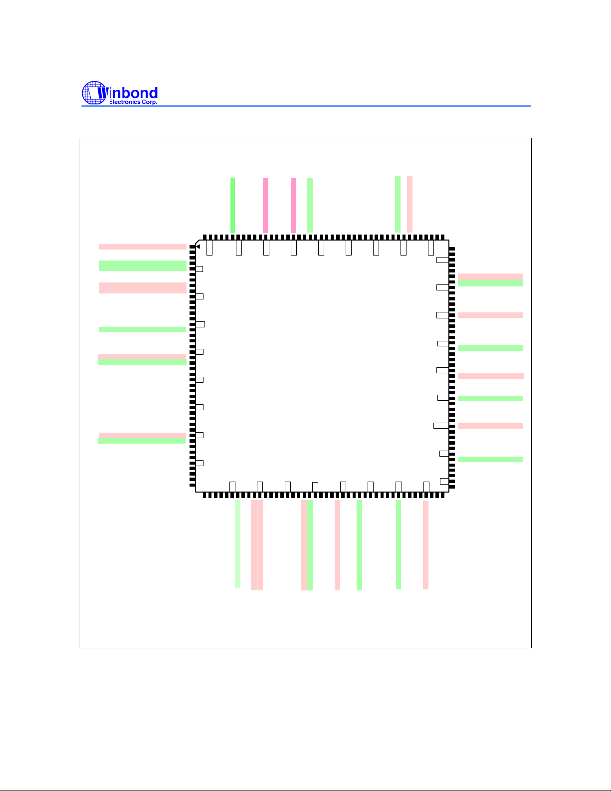
3. PIN DIAGRAM
D[0]/TBUS[0]
D[1]/TBUS[1]
D[2]/TBUS[2]
D[3]/TBUS[3]
D[4]/TBUS[4]
D[5]/TBUS[5]
VSS33
D[6]/TBUS[6]
D[7]/TBUS[7]
D[8]/TBUS[8]
D[9]/TBUS[9]
VDD33
D[10]/TBUS[10]
D[11]/TBUS[11]
D[12]/TBUS[12]
W90P710CD/W90P710CDG
nWBE[3]/SDQM[3]/GPIO[68]
nWBE[2]/SDQM[2]/GPIO[69]
D[22]/VD[14]/GPIO[58]
D[20]/VD[12]/GPIO[56]
D[21]/VD[13]/GPIO[57]
D[19]/VD[11]/GPIO[55]
D[23]/VD[15]/GPIO[59]
D[18]/VD[10]/GPIO[54]
D[17]/VD[9]/GPIO[53]
D[13]/TBUS[13]
VDD18
D[14]/TBUS[14]
D[16]/VD[8]/GPIO[52]
D[15]/TBUS[15]
VSS18
nIRQ[3]/GPIO[19]
nIRQ[2]/GPIO[18]
nWBE[0]/SDQM[0]
nWBE[1]/SDQM[1]
nSCS[1]
nSCS[0]
VDD33
nSCAS
VSS33
nSRAS
MCLK
nWE
nBTCS
MCKE
USB1VDD
DP1
DN1
USB1VSS
USB0VSS
DN0
DP0
USB0VDD
VDD33
TXD0/GPIO[5]
RXD0/GPIO[6]
TXD1/GPIO[7]
CTS1/TXD2(IrDA)/PS2_CLK/GPIO[9]
RTS1/RXD2(IrDA)/PS2_DATA/GPIO[10]
SCL0/SFRM/TIMER0/GPIO[11]
SDA0/SSPTXD/TIMER1/GPIO[12]
SCL1/SCLK/KPI_ROW[3]/GPIO[13]
SDA1/SSPRXD/KPI_ROW[2]/GPIO[14]
KPI_ROW[0]/VCLK/GPIO[30]
KPI_ROW[1]/VDEN/GPIO[31]
KPI_ROW[2]/VSYNC/GPIO[32]
KPI_ROW[3]/HSYNC/GPIO[33]
KPI_COL[7]/VD[7]/GPIO[41]
KPI_COL[6]/VD[6]/GPIO[40]
KPI_COL[5]/VD[5]/GPIO[39]
KPI_COL[4]/VD[4]/GPIO[38]
KPI_COL[3]/VD[3]/GPIO[37]
KPI_COL[2]/VD[2]/GPIO[36]
KPI_COL[1]/VD[1]/GPIO[35]
KPI_COL[0]/VD[0]/GPIO[34]
RXD1/GPIO[8]
VSS33
VDD18
VSS18
VDD33
VSS33
nRESET
TEST
PLL0VDD18
PLL0VSS18
PLL1VSS18
PLL1VDD18
nIRQ[0]/GPIO[16]
nIRQ[1]/GPIO[17]
165
160
155
SC0_CLK/SD_CLK/VD[16]/GPIO[28]
SC0_RST/SD_DAT0/VD[15]/GPIO[27]
VDD33
SC0_PRES/SD_DAT1/VD[14]/GPIO[26]
150
70
SC1_CLK/SD_PWR/VD[11]/GPIO[23]
SC0_PWR/SD_DAT2/VD[13]/GPIO[25]
SC1_DAT/SD_DAT3/VD[12]/GPIO[24]
SC1_RST/SD_CD/VD[10]/GPIO[22]
VSS33
75
SC1_PRES/nXDREQ/VD[9]GPIO[21]
175
170
5
10
15
20
25
30
35
40
TDO
TMS
TCK
TDI
W90P710
176 -pin
LQFP
50
55
60
VDD18
AC97_SYNC/I2S_LRCLK/PWM[2]/TXD3/GPIO[3]
VDD33
RTCVDD18
AC97_DATAI/I2S_DATAI/PWM[0]/DTR3/GPIO[1]
XTAL32 (32.768K)
EXTAL32 (32.768K)
AC97_nRESET/I2S_MCLK/GPIO[0]
AC97_DATAO/I2S_DATAO/PWM[1]/DSR3/GPIO[2]
AC97_BITCLK/I2S_BITCLK/PWM[3]/RXD3/GPIO[4]
nTRST
nWDOG/GPIO[15]
XTAL(15M)
VSS33
EXTAL(15M)
65
SC0_DAT/SD_CMD/VD[17]/[GPIO[29]
VSS18
145
80
PHY_RXD[0]/GPIO[44]/KPI_COL[2]/VD[10]
PHY_RXERR/GPIO[42]/KPI_COL[0]/VD[8]
SC1_PWR/nXDACK/VD[8]/GPIO[20]
VSS33
PHY_CRSDV/GPIO[43]/KPI_COL[1]/VD[9]
140
135
85
PHY_TXD[0]/GPIO[48]/KPI_COL[6]/VD[14]
PHY_TXD[1]/GPIO[49]/KPI_COL[7]/VD[15]
PHY_TXEN/GPIO[47]/KPI_COL[5]/VD[13]
PHY_REFCLK/GPIO[46]/KPI_COL[4]/VD[12]
PHY_RXD[1]/GPIO[45]/KPI_COL[3]/VD[11]
VDD33
nWAIT/TREQB
nOE
nECS[0]
130
nECS[1]
nECS[2]
VDD33
VSS33
125
nECS[3]
D[24]/VD[16]/GPIO[60]
D[25]/VD[17]/GPIO[61]
D[26]/VD[18]/GPIO[62]
D[27]/VD[19]/GPIO[63]
120
VDD33
D[28]/VD[20]/GPIO[64]
D[29]/VD[21]/GPIO[65]
D[30]/VD[22]/GPIO[66]
D[31]/VD[23]/GPIO[67]
A[21]
115
VSS33
A[20]
A[19]
A[18]
110
A[17]/TREQA
VDD18
A[16]/TACK
A[15]/TBUS[31]
A[14]/TBUS[30]
105
VSS18
A[13]/TBUS[29]
A[12]/TBUS[28]
A[11]/TBUS[27]
A[10]/TBUS[26]
100
VDD33
A[9]/TBUS[25]
A[8]/TBUS[24]
A[7]/TBUS[23]
A[6]/TBUS[22]
95
A[5]/TBUS[21]
VSS33
A[4]/TBUS[20]
A[3]/TBUS[19]
A[2]/TBUS[18]
90
A[1]/TBUS[17]
A[0]/TBUS[16]
PHY_MDIO/GPIO[50]/KPI_ROW[0]/VD[16]
PHY_MDC/GPIO[51]/KP_ROW[1]/VD[17]
Fig 3.1 Pin Diagram
Publication Release Date: September 19, 2006
- 13 - Revision B2
W90P710CD/W90P710CDG
4. PIN ASSIGNMENT
Table 4.1 W90P710 Pins Assignment
PIN NAME 176-PIN LQFP
Clock & Reset ( 5 pins )
EXTAL (15M) 52
XTAL (15M) 53
EXTAL32 (32.768K) 57
XTAL32 (32.768K) 56
nRESET 37
JTAG Interface ( 5 pins )
TMS 45
TDI 46
TDO 47
TCK 48
nTRST 49
External Bus Interface ( 72 pins )
A [21] 115
A [20:0]
D [31:16] /
VD [23:8] /
GPIO [67:52]
D [15:0] 158,159,161-164, 166-170,172-176
nWBE [3:2] /
SDQM [3:2] /
GPIO[69:68]
nWBE [1;0] /
SDQM [1:0]
nSCS [1:0] 136,135
nSRAS 137
nSCAS 138
MCKE 134
nSWE 142
MCLK 140
nWAIT/
GPIO[70] /
nIRQ5
nBTCS 133
nECS [3] 125
nECS [2:0] 128-130
nOE 131
113-110,108-106,
104-101,99-95, 93-89
116-119,121-124, 149-156
146,145
144,143
132
- 14 -

W90P710CD/W90P710CDG
Table 4.1 W90P710 Pins Assignment (Continued)
PIN NAME 176-PIN LQFP
Ethernet Interface ( 10 pins )
PHY_MDC /
GPIO [51] / KPROW[1] /
VD[17]
PHY_MDIO /
GPIO [50] /
KPROW[0] /
LD[16]
PHY_TXD [1:0] /
GPIO[49:48] /
KPCOL[7:6] /
VD[15:14]
PHY_TXEN /
GPIO [47] /
KPCOL[5] /
VD[13]
PHY_REFCLK /
GPIO [46] /
KPCOL[4] /
VD[12]
PHY_RXD [1:0] /
GPIO [45:44] /
KPCOL[3:2] /
VD[11:10]
PHY_CRSDV /
GPIO [43] /
KPCOL[1] /
VD[9]
PHY_RXERR /
GPIO [42] /
KPCOL[0] /
VD[8]
AC97/I2S/PWM/UART3 ( 5 pins )
AC97_nRESET /
I2S_MCLK /
GPIO [0] /
USB_PWREN
88
87
86,84
83
82
81,79
78
77
58
Publication Release Date: September 19, 2006
- 15 - Revision B2
W90P710CD/W90P710CDG
Table 4.1 W90P710 Pins Assignment (Continued)
PIN NAME 176-PIN LQFP
AC97/I2S/PWM/UART3 ( 5 pins )
AC97_DATAI /
I2S_DATAI /
PWM [0] /
DTR3 /
GPIO [1]
AC97_DATAO /
I2S_DATAO /
PWM [1] /
DSR3 /
GPIO [2]
AC97_SYNC /
I2S_LRCLK /
PWM [2] /
TXD3 /
GPIO [3]
AC97_BITCLK /
I2S_BITCLK /
PWM [3] /
RXD3
GPIO [4]
USB Interface ( 4 pins )
DP0 7
DN 0 6
DP1 2
DN1 3
Miscellaneous ( 7 pins )
nIRQ [3:2] /
GPIO [19:18]
nIRQ [1] /
GPIO [17] /
USB_OVRCUR
nIRQ [0] /
GPIO [16]
nWDOG /
GPIO [15] /
USB_PWREN
RTCVDD18 55
59
60
61
62
148,147
44
43
50
- 16 -
W90P710CD/W90P710CDG
Table 4.1 W90P710 Pins Assignment (Continued)
NAME 176-PIN LQFP
I2C/USI(Microwire/SPI) ( 4 pins )
SCL0 /
SFRM /
Timer0 /
GPIO [11]
SDA0 /
SSPTXD /
Timer1 /
GPIO [12]
SCL1 /
SCLK /
GPIO [13] /
KPROW[3]
SDA1 /
SSPRXD /
GPIO [14] /
KPROW[2]
UART0/UART1/UART2/PS2 ( 6 pins )
TXD0 /
GPIO [5]
RXD0 /
GPIO [6]
TXD1 /
GPIO [7]
RXD1 /
GPIO [8]
CTS1 /
TXD2(IrDA) /
PS2_CLK /
GPIO [9]
RTS1 /
RXD2(IrDA) /
PS2_DATA /
GPIO [10]
17
18
19
20
10
11
12
13
14
15
Publication Release Date: September 19, 2006
- 17 - Revision B2

W90P710CD/W90P710CDG
Table 4.1 W90P710 Pins Assignment (Continued)
NAME 176-PIN LQFP
SCHI/SD/XDMA ( 10 pins )
SC0_DAT /
SD_CMD /
GPIO [29] /
VD[17]
SC0_CLK /
SD_CLK /
GPIO [28] /
VD[16]
SC0_RST /
SD_DAT0 /
GPIO [27] /
VD[15]
SC0_PRES /
SD_DAT1 /
GPIO [26] /
VD[14]
SC0_PWR /
SD_DAT2 /
GPIO [25] /
VD[13]
SC1_DAT /
SD_DAT3 /
GPIO [24] /
VD[12]
SC1_CLK /
GPIO [23] /
VD[11]
SC1_RST /
SD_CD /
GPIO [22] /
VD[10]
SC1_PRES /
nXDREQ /
GPIO [21] /
VD[9]
SC1_PWR /
nXDACK /
GPIO [20] /
VD[8]
65
66
67
68
70
71
72
74
75
76
- 18 -
W90P710CD/W90P710CDG
Table 4.1 W90P710 Pins Assignment (Continued)
NAME 176-PIN LQFP
LCDC ( 12 pins )
VD[7:0] /
GPIO [41:34]/
KPCOL[7:0]
HSYNC /
GPIO [33]/
KPROW[3]
VSYNC /
GPIO [32]/
KPROW[2]
VDEN /
GPIO [31]/
KPROW[1]
VCLK /
GPIO [30]/
KPROW[0]
Power/Ground ( 36 pins )
VDD18 21,63,109,160
VSS18 22,38,64,105,157
VDD33
VSS33
USBVDD 1,8
USBVSS 4,5
PLLVDD18 39,42
PLLVSS18 40,41
27-34
26
25
24
23
9,35,54,69,85,100,
120,127,139,165
16,36,51,73,80,94,
114,126,141,171
Publication Release Date: September 19, 2006
- 19 - Revision B2
W90P710CD/W90P710CDG
5. PIN DESCRIPTION
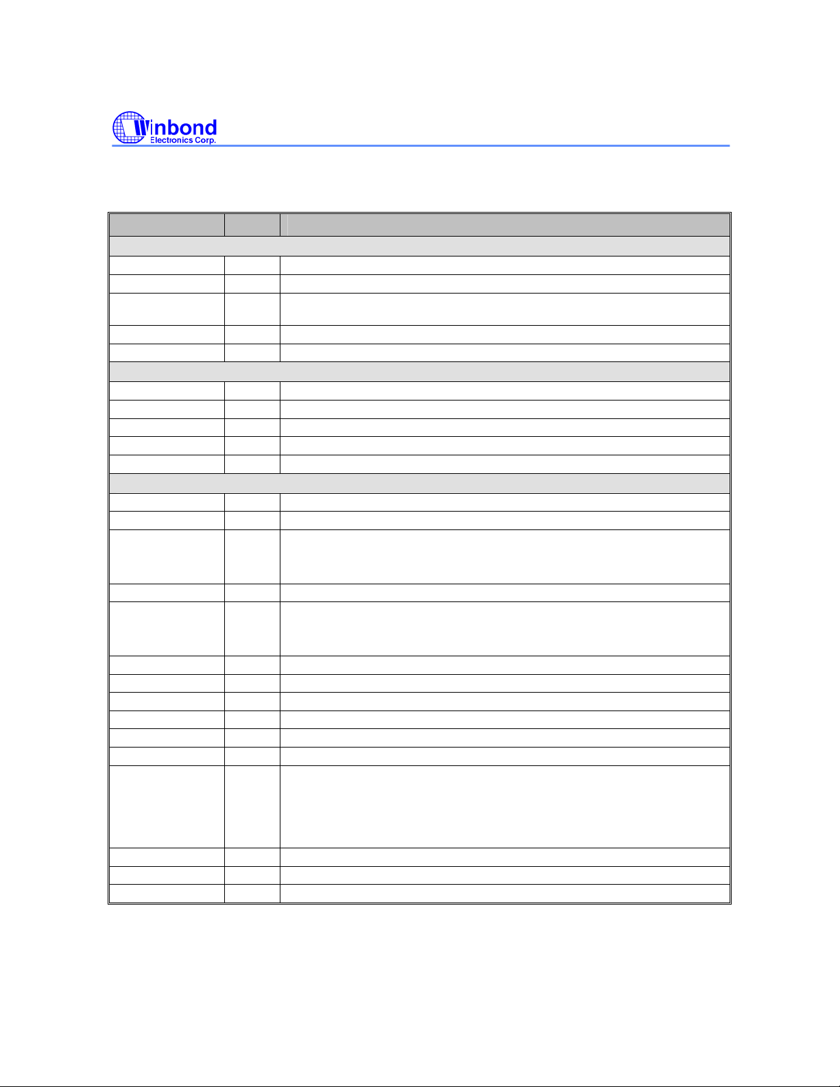
Table 5.1 W90P710 Pins Description
PIN NAME IO TYPE DESCRIPTION
Clock & Reset
EXTAL (15M) I 15MHz External Clock / Crystal Input
XTAL (15M) O 15MHz Crystal Output
EXTAL32(32.768
K)
XTAL32(32.768K) O 32768Hz Crystal Output(for RTC)
nRESET IS System Reset, active-low
JTAG Interface
TCK IDS JTAG Test Clock, internal pull-down with 58K ohm
TMS IUS JTAG Test Mode Select, internal pull-up with 70K ohm
TDI IUS JTAG Test Data in, internal pull-up with 70K ohm
TDO O JTAG Test Data out
nTRST IUS JTAG Reset, active-low, internal pull-up with 70K ohm
External Bus Interface
A [21:18] O Address Bus (MSB) of external memory and IO devices.
A [17:0] IOS Address Bus of external memory and IO devices.
D [31:16] /
VD[23:8] /
GPIO [67:52]
D [15:0] / IOU Data Bus (LSB) of external memory and IO device.
nWBE [3:0] /
SDQM [3:0] /
GPIO[69:68]
nSCS [1:0] O SDRAM chip select for two external banks, active-low.
nSRAS O Row Address Strobe for SDRAM, active-low.
nSCAS O Column Address Strobe for SDRAM, active-low.
nSWE O SDRAM Write Enable, active-low
MCKE O SDRAM Clock Enable, active-high
MCLK O System Master Clock Out, SDRAM clock, output with slew-rate control
nWAIT /
GPIO[70] /
nIRQ5
nBTCS O ROM/Flash Chip Select, active-low.
nECS [3:0] O External I/O Chip Select, active-low.
nOE O ROM/Flash, External Memory Output Enable, active-low.
I 32768Hz External Clock / Crystal Input(for RTC)
Data Bus (MSB) of external memory and IO device, internal pull-up with 70K
IOU
IOU
IOU
ohm.
General Programmable In/Out Port GPIO[67:52].
Write Byte Enable for specific device (nECS [3:0]).
Data Bus Mask signal for SDRAM (nSCS [1:0]), active-low.
General Programmable In/Out Port [69:68]
External Wait, active-low.
This pin indicates that the external devices need more active cycle during
access operation.
General Programmable In/Out Port GPIO[70]. If memory and IO devices in EBI
do not need wait request, it can be configured as GPIO[7] or nIRQ5
- 20 -

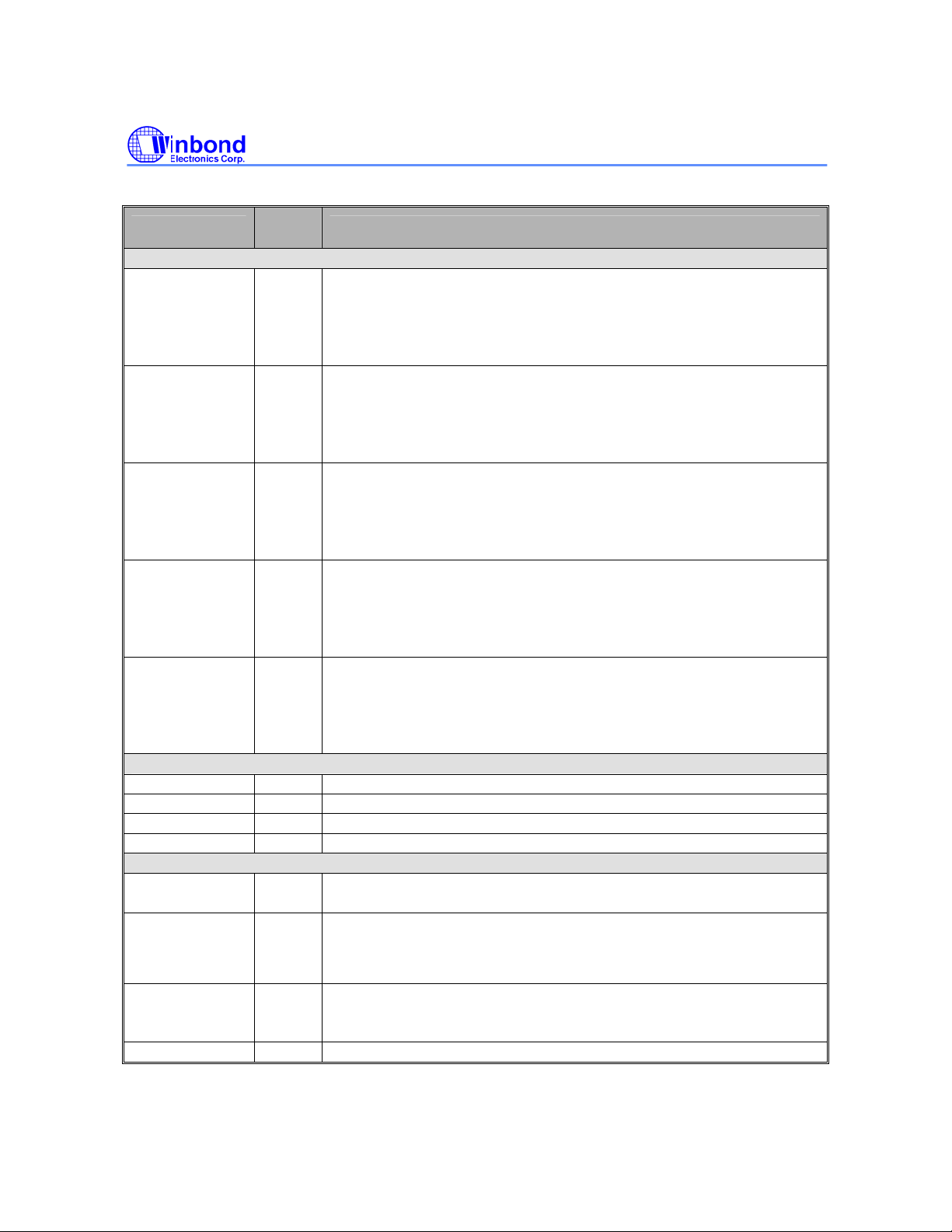
Table 5.1 W90P710 Pins Description (Continued)
Pin Name
Ethernet Interface
PHY_MDC /
GPIO [51] /
KPROW[1] /
VD[17]
PHY_MDIO /
GPIO [50] /
KPROW[0] /
VD[16]
PHY_TXD [1:0] /
GPIO [49:48] /
KPCOL[7:6] /
VD[15]
PHY_TXEN /
GPIO [47] /
KPCOL[5] /
VD[14:13]
PHY_REFCLK /
GPIO [46] /
KPCOL[4] /
VD[12]
PHY_RXD [1:0] /
GPIO [45:44] /
KPCOL[3:2] /
VD[11:10]
PHY_CRSDV /
GPIO [43] /
KPCOL[1] /
VD[9]
PHY_RXERR /
GPIO [42] /
KPCOL[0] /
VD[8]
IO
Type
IOU
IO
IOU
IOU
IOS
IOS
IOS
IOS
Description
RMII Management Data Clock for Ethernet. It is the reference clock of MDIO.
Each MDIO data will be latched at the rising edge of MDC clock.
General Programmable In/Out Port [51]
Keypad ROW[1] scan output.
LCD Pixel Data Output[17]
RMII Management Data I/O for Ethernet. It is used to transfer RMII control and
status information between PHY and MAC.
General Programmable In/Out Port [51]
Keypad ROW[0] scan output.
LCD Pixel Data Output[16]
2-bit Transmit Data bus for Ethernet.
General programmable In/Out Port [49:48]
Keypad Column input [7:6], active low
LCD Pixel Data Output[15].
PHY_TXEN shall be asserted synchronously with the first 2-bit of the preamble
and shall remain asserted while all di-bits to be transmitted are presented. Of
course, it is synchronized with PHY_REFCLK.
General Programmable In/Out Port [47]
Keypad column input [5], active low
LCD Pixel Data Output[14:13]
Reference Clock. The clock shall be 50MHz +/- 50 ppm with minimum 35%
duty cycle at high or low state.
General Programmable In/Out port [46]
Keypad column input [4], active low
LCD Pixel Data Output[12]
2-bit Receive Data bus for Ethernet.
General Programmable In/Out Port [45:44]
Keypad column input [3:2], active low
LCD Pixel Data Output[11:10].
Carrier Sense / Receive Data Valid for Ethernet. The PHY_CRSDV shall be
asserted by PHY when the receive medium is non-idle. Loss of carrier shall
result in the de-assertion of PHY_CRSDV synchronous to the cycle of
PHY_REFCLK, and only on 2-bit receive data boundaries.
General Programmable In/Out port [43]
Keypad column input [1], active low
LCD Pixel Data Output[9]
Receive Data Error for Ethernet. It indicates a data error detected by PHY.The
assertion should be lasted for longer than a period of PHY_REFCLK. When
PHY_RXERR is asserted, the MAC will report a CRC error.
General programmable In/Out port [42]
Keypad column input [0], active low
LCD Pixel Data Output[8]
W90P710CD/W90P710CDG
.
.
.
.
.
.
Publication Release Date: September 19, 2006
- 21 - Revision B2
W90P710CD/W90P710CDG
Table 5.1 W90P710 Pins Description (Continued)
Pin Name
AC97/I2S/PWM/UART3
AC97_nRESET /
I2S_MCLK /
GPIO [0] /
nIRQ4 /
USB_PWREN
AC97_DATAI /
I2S_DATAI /
PWM [0] /
DTR4 /
GPIO [1]
AC97_DATAO /
I2S_DATAO /
PWM [1] /
DSR4 /
GPIO [2]
AC97_SYNC /
I2S_LRCLK /
PWM [2] /
TXD4 /
GPIO [3]
AC97_BITCLK /
I2S_BITCLK /
PWM [3] /
RXD4 /
GPIO [4]
USB Interface
DP0 IO Differential Positive USB IO signal
DN0 IO Differential Negative USB IO signal
DP1 IO Differential Positive USB IO signal
DN1 IO Differential Negative USB IO signal
Miscellaneous
nIRQ [3:2] /
GPIO [19:18]
nIRQ [1:0] /
GPIO [17:16]
USB_OVRCUR
nWDOG /
GPIO [15] /
USB_PWREN
RTCVDD P RTC independent battery power (1.8V)
IO
Type
IOU
IOU
IOU
IOU
IOS
IOU
IOU
IOU
Description
AC97 CODEC Host Interface RESET Output.
I2S CODEC Host Interface System Clock Output.
General Purpose In/Out port [0]
External interrupt request.
USB host power enable output
AC97 CODEC Host Interface Data Input.
I2S CODEC Host Interface Data Input.
PWM Channel 0 Output.
Data Terminal Ready for UART4.
General Purpose In /Out port [1]
AC97 CODEC Host Interface Data Output.
I2S CODEC Host Interface Data Output.
PWM Channel 1 Output.
Data Set Ready for UART4.
General Purpose In/Out port [2]
AC97 CODEC Host Interface Synchronous Pulse Output.
I2S CODEC Host Interface Left/Right Channel Select Clock.
PWM Channel 2 Output.
Transmit Data for UART4.
General Purpose In/Out port [3]
AC97 CODEC Host Interface Bit Clock Input.
I2S CODEC Host Interface Bit Clock.
PWM Channel 3 Output.
Receive Data for UART4.
General Purpose In/Out port [4].
External Interrupt Request
General Purpose I/O.
External Interrupt Request
General Purpose I/O
nIRQ1 is used as USB host over-current detection input
Watchdog Timer Timeout Flag and Keypad 3-keys reset output, active low
General Purpose In/output
USB host power switch enable output
- 22 -
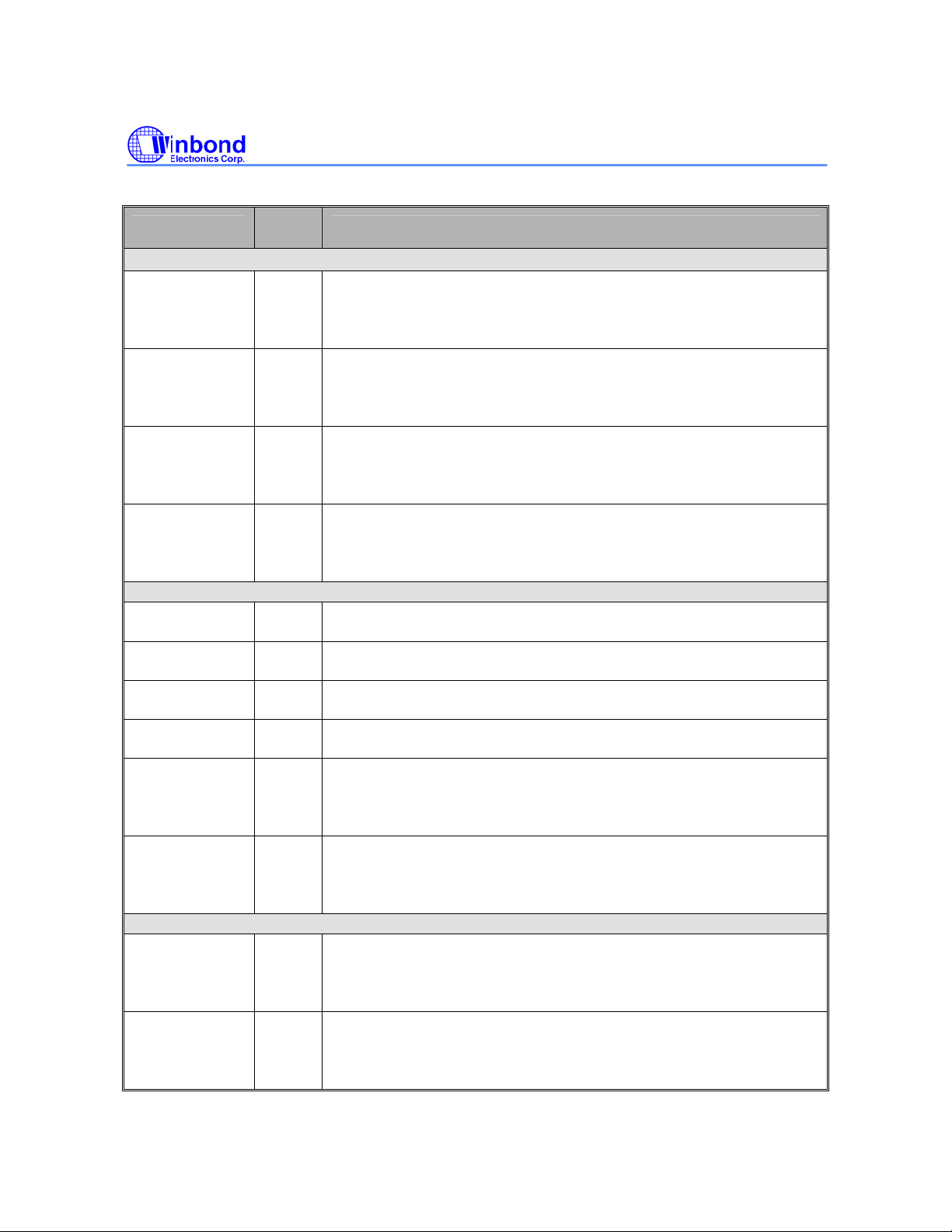
Table 5.1 W90P710 Pins Description (Continued)
Pin Name
I2C/USI(Microwire/SPI)
SCL0 /
SFRM /
Timer0 /
GPIO [11]
SDA0 /
SSPTXD /
Timer1 /
GPIO [12]
SCL1 /
SCLK /
GPIO [13]
KPROW[3]
SDA1 /
SSPRXD /
GPIO [14] /
KPROW[2]
UART0/UART1/UART2
TXD0 /
GPIO [5]
RXD0 /
GPIO [6]
TXD1 /
GPIO [7]
RXD1 /
GPIO [8]
CTS1/
TXD2(IrDA) /
PS2_CLK /
GPIO [9]
RTS1/
RXD2(IrDA) /
PS2_DATA /
GPIO [10]
SCHI/SD/XDMA
SC0_DAT/
SD_CMD /
GPIO [29] /
VD[17]
SC0_CLK /
SD_CLK /
GPIO [28] /
VD[16]
IO
Type
IOU
IOU
IOU
IDU
IOU
IOU
IOU
IOU
IOU
IOU
IOU
IO
Description
I2C Serial Clock Line 0.
USI Serial Frame.
Timer0 time out output.
General Purpose In/Out port [11].
I2C Serial Data Line 0
USI Serial Transmit Data
Timer1 time out output
General Purpose In/Out port [12]
I2C Serial Clock Line 1
USI Serial Clock
General Purpose In/Out port [13]
Keypad row scan output [3]
I2C Serial Data Line 1
USI Serial Receive Data
General Purpose In/Out port [14]
Keypad scan output [2]
UART0 Transmit Data.
General Purpose In/Out [5]
UART0 Receive Data.
General Purpose In/Out [6]
UART1 Transmit Data.
General Purpose In/Out [7]
UART1 Receive Data.
General Purpose In/Out [8]
UART1 Clear To Send for Bluetooth application
UART2 Transmit Data supporting SIR IrDA.
PS2 Interface Clock Input/Output
General Purpose In/Out [9]
UART1 Request To Send for Bluetooth application
UART2 Receive Data supporting SIR IrDA.
PS2 Interface Bi-Directional Data Line.
General Purpose In/Out [10]
Smart Card I/O Contact to Card 0.
SD Mode – Command/Response;
General Purpose In/Out [29]
LCD Pixel Data Output[17]
Smart Card Clock Output to Card 0.
SD Mode – Clock;
General Purpose In/Out [28]
LCD Pixel Data Output[16].
W90P710CD/W90P710CDG
.
Publication Release Date: September 19, 2006
- 23 - Revision B2

Table 5.1 W90P710 Pins Description (Continued)
Pin Name
SCHI/SD/XDMA
SC0_RST /
SD_DAT0 /
GPIO [27] /
VD[15]
SC0_PRES /
SD_DAT1 /
GPIO [26]
VD[14]
SC0_nPWR /
SD_DAT2 /
GPIO [25] /
VD[13]
SC1_DAT /
SD_DAT3 /
GPIO [24] /
VD[12]
SC1_CLK /
GPIO [23] /
VD[11]
SC1_RST /
SD_CD /
GPIO [22] /
VD[10]
SC1_PRES /
nXDREQ /
GPIO [21] /
VD[9]
SC1_nPWR /
nXDACK /
GPIO [20] /
VD[8]
LCD Interface
VD [7:0] /
GPIO [41:34]/
KPCOL[7:0]
HSYNC /
GPIO [33]/
KPROW[3]
VSYNC /
GPIO [32]/
KPROW[2]
VDEN /
GPIO [31]/
KPROW[1]
IO
Type
IO
IO
IO
IO
IO
IO
IO
IO
IOU
IOU
IOU
IOU
Description
Smart Card Reset Output to Card 0.
SD Mode – Data Line Bit 0;
General Purpose In/Out [27]
LCD Pixel Data Output[15]
Smart Card 0 Presence Contact Input.
SD Mode – Data Line Bit 1.
General Purpose In/Out [26]
LCD Pixel Data Output[14]
Smart Card 0 Power FET Control Signal Output.
SD Mode – Data Line Bit 2.
General Purpose In/Out [25]
LCD Pixel Data Output[13].
Smart Card I/O Contact to Card 1.
SD Mode – Data Line Bit 3;
General Purpose In/Out [24]
LCD Pixel Data Output[12]
Smart Card Clock Output to Card 1.
General Purpose In/Out [23]
LCD Pixel Data Output[11]
Smart Card Reset Output to Card 1.
SD Mode – Card Detect.
General Purpose In/Out [22]
LCD Pixel Data Output[10]
Smart Card 1 Presence Contact Input.
External DMA Request.
General Purpose In/Out [21]
LCD Pixel Data Output[9]
Smart Card 1 Power FET Control Signal Output.
External DMA Acknowledgement.
General Purpose In/Out [20]
LCD Pixel Data Output[8]
LCD Pixel Data Output [7:0].
General Purpose In/Out [41:34]
Keypad Column input [7:0], active low
Horizontal Sync
General Purpose In/Out [33]
Keypad ROW[3] scan output.
Vertical Sync
General Purpose In/Out [32]
Keypad ROW[2] scan output.
Data Enable or Display Control Signal.
General Purpose In/Out [31]
Keypad ROW[1] scan output.
W90P710CD/W90P710CDG
.
.]
.
.
.
.
.
- 24 -
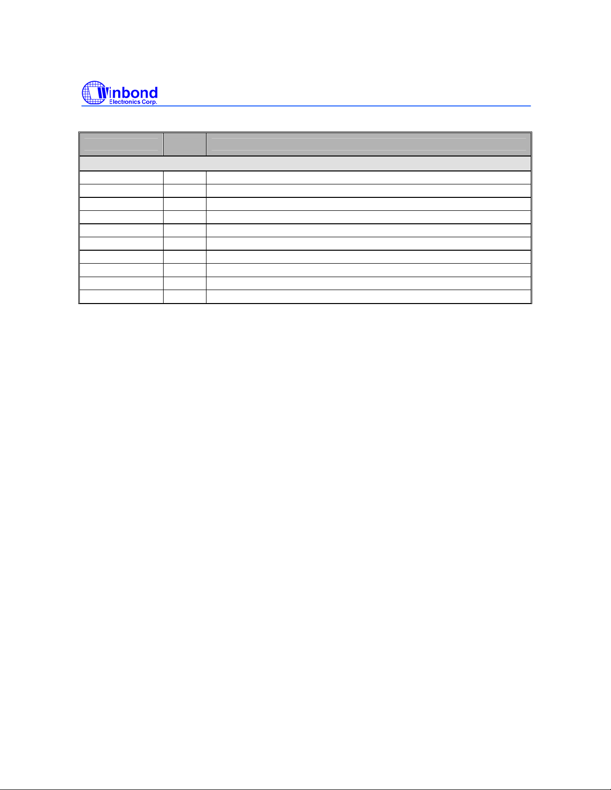
Table 5.1 W90P710 Pins Description (Continued)
Pin Name
Power/Ground
VDD18 P Core Logic power (1.8V)
VSS18 G Core Logic ground (0V)
VDD33 P IO Buffer power (3.3V)
VSS33 G IO Buffer ground (0V)
USBVDD P USB power (3.3V)
USBVSS G USB ground (0V)
DVDD18 P PLL Digital power (1.8V)
DVSS18 G PLL Digital ground (0V)
AVDD18 P PLL Analog power (1.8V)
AVSS18 G PLL Analog ground (0V)
IO
Type
Description
W90P710CD/W90P710CDG
Publication Release Date: September 19, 2006
- 25 - Revision B2
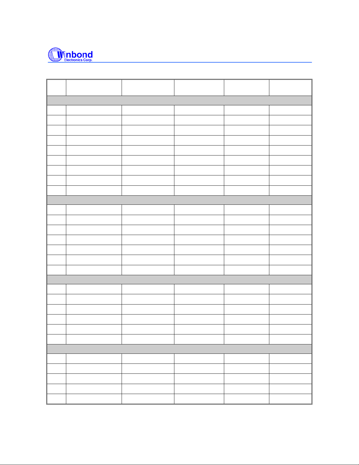
W90P710CD/W90P710CDG
Table 5.2 W90P710 176-pin LQFP Multi-function List
PIN
NO.
1 USB1VDD
2 DP1
3 DN1
4 USB1VSS
5 USB0VSS
6 DN0
7 DP0
8 USB0VDD
9 VDD33
10 GPIO[5]
11 GPIO[6]
12 GPIO[7]
13 GPIO[8]
14 GPIO[9]
DEFAULT FUNCTION0 FUNCTION1 FUNCTION2 FUNCTION3
USB1.1 Host/Device Interface
USB1VDD - - -
DP1 - - -
DN1 - - -
USB1VSS - - -
USB0VSS - - -
DN0 - - -
DP0 - - -
USB0VDD - - -
VDD33 - - -
UART[2:0]/PS2 Interface
GPIO[5] UART_TXD0 - -
GPIO[6] UART_RXD0 - -
GPIO[7] UART_TXD1 - -
GPIO[8] UART_RXD1 - -
GPIO[9] UART_TXD2 UART_CTS1 PS2_CLK
15 GPIO[10]
16 VSS33
17 GPIO[11]
18 GPIO[12]
19 GPIO[13]
20 GPIO[14]
21 VDD18
22 VSS18
23 GPIO[30]
24 GPIO[31]
25 GPIO[32]
26 GPIO[33]
27 GPIO[41]
GPIO[10] UART_RXD2 UART_RTS1 PS2_DATA
VSS33 - - -
I2C/USI Interface
GPIO[11] I2C_SCL0 SSP_FRAM TIMER0
GPIO[12] I2C_SDA0 SSP_TXD TIMER1
GPIO[13] I2C_SCL1 SSP_RXD KPROW[2]
GPIO[14] I2C_SDA1 SSP_SCLK KPROW[3]
VDD18 - - -
VSS18 - - -
LCD /KeyPad Interface
GPIO[30] LCD_VCLK KPROW[0] -
GPIO[31] LCD_VDEN KPROW[1] -
GPIO[32] LCD_VSYNC KPROW[2] -
GPIO[33] LCD_HSYNC KPROW[3] -
GPIO[41] LCD_VD[7] KPCOL[7] -
- 26 -
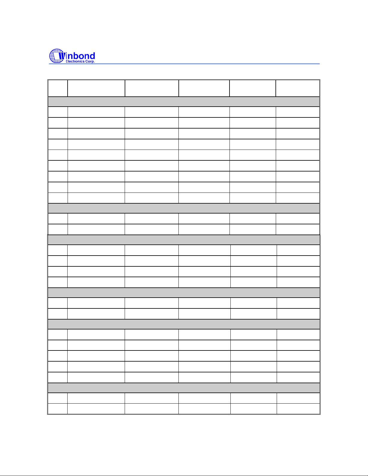
Table 5.2 W90P710 176-pin LQFP Multi-function List (Continued)
W90P710CD/W90P710CDG
PIN
NO.
28 GPIO[40]
29 GPIO[39]
30 GPIO[38]
31 GPIO[37]
32 GPIO[36]
33 GPIO[35]
34 GPIO[34]
35 VDD33
36 VSS33
37 nRESET
38 VSS33
39 PLL0_VDD18
DEFAULT FUNCTION0 FUNCTION1 FUNCTION2 FUNCTION3
LCD /KeyPad Interface
GPIO[40] LCD_VD[6] KPCOL[6] -
GPIO[39] LCD_VD[5] KPCOL[5] -
GPIO[38] LCD_VD[4] KPCOL[4] -
GPIO[37] LCD_VD[3] KPCOL[3] -
GPIO[36] LCD_VD[2] KPCOL[2] -
GPIO[35] LCD_VD[1] KPCOL[1] -
GPIO[34] LCD_VD[0] KPCOL[0] -
VDD33 - - -
VSS33 - - -
System Reset
nRESET - - -
VSS33 - - -
PLL Power/Ground
PLL0_VDD18 - - -
40 PLL0_VSS18
41 PLL1_VSS18
42 PLL1_VDD18
43 GPIO[16]
44 GPIO[17]
45 TMS
46 TDI
47 TDO
48 TCK
49 nTRST
50 GPIO[15]
51 VSS33
PLL0_VSS18 - - -
PLL1_VSS18 - - -
PLL1_VDD18 - - -
External IRQ[1:0]/USB Over Current
GPIO[16] nIRQ[0] - -
GPIO[17] nIRQ[1] USB_OVRCUR -
JTAG Interface
TMS - - -
TDI - - -
TDO - - -
TCK - - -
nTRST - - -
WatchDog/USB Power Enable
GPIO[15] nWDOG USB_PWREN -
VSS33 - - -
Publication Release Date: September 19, 2006
- 27 - Revision B2
Table 5.2 W90P710 176-pin LQFP Multi-function List (Continued)
W90P710CD/W90P710CDG
PIN
NO.
52 EXTAL(15M)
53 XTAL(15M)
54 VDD33
55 RTCVDD18
56 XTAL32 (32K)
57 EXTAL32 (32K)
58 GPIO[0]
59 GPIO[1]
60 GPIO[2]
61 GPIO[3]
62 GPIO[4]
63 VDD18
DEFAULT FUNCTION0 FUNCTION1 FUNCTION2 FUNCTION3
System/RTC Clock
EXTAL(15M) - - -
XTAL(15M) - - -
VDD33 - - -
RTCVDD18 - - -
XTAL32 (32K) - - -
EXTAL32 (32K) - - -
AC97/I2S/PWM/UART3 Interface
GPIO[0]
GPIO[1]
GPIO[2]
GPIO[3]
GPIO[4]
VDD18
AC97_nRESET
AC97_DATAI
AC97_DATAO
AC97_SYNC
AC97_BITCLK
-
IRQ4 USB_PWREN
PWM0 UART_DTR3
PWM1 UART_DSR3
PWM2 UART_TXD3
PWM3 UART_RXD3
- -
64 VSS18
SmartCard/SD/USB Power/XDMAREQ/LCD Interace
65 GPIO[29]
66 GPIO[28]
67 GPIO[27]
68 GPIO[26]
69 VDD33
70 GPIO[25]
71 GPIO[24]
72 GPIO[23]
73 VSS33
74 GPIO[22]
75 GPIO[21]
76 GPIO[20]
VSS18 - - -
GPIO[29] SD_CMD SC0_IO LCD_VD[17]
GPIO[28] SD_CLK SC0_CLK LCD_VD[16]
GPIO[27] SD_DAT[0] SC0_RST LCD_VD[15]
GPIO[26] SD_DAT[1] SC0_PRES LCD_VD[14]
VDD33
GPIO[25] SD_DAT[2] SC0_PWR LCD_VD[13]
GPIO[24] SD_DAT[3] SC1_IO LCD_VD[12]
GPIO[23] USBPWREN SC1_CLK LCD_VD[11]
VSS33
GPIO[22] SD_CD SC1_RST LCD_VD[10]
GPIO[21] nXQREQ SC1_PRES LCD_VD[9]
GPIO[20] nXDACK SC1_PWR LCD_VD[8]
- 28 -
Table 5.2 W90P710 176-pin LQFP Multi-function List (Continued)
W90P710CD/W90P710CDG
PIN
NO.
77 GPIO[42]
78 GPIO[43]
79 GPIO[44]
80 VSS33
81 GPIO[45]
82 GPIO[46]
83 GPIO[47]
84 GPIO[48]
85 VDD33
86 GPIO[49]
87 GPIO[50]
88 GPIO[51]
89 A[0]
DEFAULT FUNCTION0 FUNCTION1 FUNCTION2 FUNCTION3
Ethernet RMII/KeyPad Interface
GPIO[42] PHY_RXERR KPCOL[0] LCD_VD[8]
GPIO[43] PHY_CRSDV KPCOL[1] LCD_VD[9]
GPIO[44] PHY_RXD[0] KPCOL[2] LCD_VD[10]
VSS33 - - -
GPIO[45] PHY_RXD[1] KPCOL[3] LCD_VD[11]
GPIO[46] PHY_REFCLK KPCOL[4] LCD_VD[12]
GPIO[47] PHY_TXEN KPCOL[5] LCD_VD[13]
GPIO[48] PHY_TXD[0] KPCOL[6] LCD_VD[14]
VDD33 - -
GPIO[49] PHY_TXD[1] KPCOL[7] LCD_VD[15]
GPIO[50] PHY_MDIO KPROW[0] LCD_VD[16]
GPIO[51] PHY_MDC KPROW[1] LCD_VD[17]
Memory Address/Data/Control
A[0] - - -
90 A[1]
91 A[2]
92 A[3]
93 A[4]
94 VSS33
95 A[5]
96 A[6]
97 A[7]
98 A[8]
99 A[9]
100 VDD33
101 A[10]
102 A[11]
103 A[12]
104 A[13]
A[1] - - -
A[2] - - -
A[3] - - -
A[4] - - -
VSS33 - - -
A[5] - - -
A[6] - - -
A[7] - - -
A[8] - - -
A[9] - - -
VDD33 - - -
A[10] - - -
A[11] - - -
A[12] - - -
A[13] - - -
Publication Release Date: September 19, 2006
- 29 - Revision B2
Table 5.2 W90P710 176-pin LQFP Multi-function List (Continued)
W90P710CD/W90P710CDG
PIN
NO.
105 VSS18
106 A[14]
107 A[15]
108 A[16]
109 VDD18
110 A[17]
111 A[18]
112 A[19]
113 A[20]
114 VSS33
115 A[21]
116 D[31]
117 D[30]
118 D[29]
119 D[28]
DEFAULT FUNCTION0 FUNCTION1 FUNCTION2 FUNCTION3
Memory Address/Data/Control
VSS18 - - -
A[14] - - -
A[15] - - -
A[16] - - -
VDD18 - - -
A[17] - - -
A[18] - - -
A[19] - - -
A[20] - - -
VSS33 - - -
A[21] - - -
GPIO[67] D[31] LCD_VD[23] -
GPIO[66] D[30] LCD_VD[22] -
GPIO[65] D[29] LCD_VD[21] -
GPIO[64] D[28] LCD_VD[20] -
120 VDD33
121 D[27]
122 D[26]
123 D[25]
124 D[24]
125 nECS[3]
126 VSS33
127 VDD33
128 nECS[2]
129 nECS[1]
130 nECS[0]
131 nOE
132 nWAIT
133 nBTCS
134 MCKE
VDD33 - - -
GPIO[63] D[27] LCD_VD[19] -
GPIO[62] D[26] LCD_VD[18] -
GPIO[61] D[25] LCD_VD[17] -
GPIO[60] D[24] LCD_VD[16] -
nECS[3] - - -
VSS33 - - -
VDD33 - - -
nECS[2] - - -
nECS[1] - - -
nECS[0] - - -
nOE - - -
GPIO[71] nWAIT IRQ5 -
nBTCS - - -
MCKE - - -
- 30 -
 Loading...