

Winbond Electronics W89C982AF Datasheet

Preliminary W89C982AF
INTEGRATED MULTIPLE REPEATER II
GENERAL DESCRIPTION................................................................................................................. 2
FEATURES........................................................................................................................................ 2
ORDERING INFORMATION.............................................................................................................. 2
SYSTEM DIAGRAM .......................................................................................................................... 3
PIN CONFIGURATION...................................................................................................................... 3
PIN DESCRIPTION ........................................................................................................................... 4
BLOCK DIAGRAM............................................................................................................................. 8
FUNCTIONAL DESCRIPTION........................................................................................................... 8
AUI Interface and Twisted Pair Line Transceiver..........................................................................................8
Link Test Function.........................................................................................................................................8
Automatic Polarity Reversal Function...........................................................................................................9
Port Partition/Reconnection Logic.................................................................................................................9
Port Status Direct Report Function...............................................................................................................9
Initial State After Reset...............................................................................................................................11
Management Logic and Management Interface .........................................................................................11
IMPR II Programmable Options..................................................................................................................15
The IMPR II Kernel Logic............................................................................................................................15
Inter-IMPR II Interface.................................................................................................................................16
ABSOLUTE MAXIMUM RATINGS................................................................................................... 17
DC CHARACTERISTICS................................................................................................................. 17
AC CHARACTERISTICS ................................................................................................................. 19
System Clock Timing..................................................................................................................................19
Reset Timing...............................................................................................................................................19
Management Bus Clock Timing..................................................................................................................20
Management Bus Carrier Sense Timing.....................................................................................................20
Inter-IMPR II Interface Input Timing............................................................................................................21
Inter-IMPR II Interface Output Timing .........................................................................................................22
Inter-IMPR II Interface Collision Timing.......................................................................................................23
Inter-IMPR II Interface to AUI/TP Port Timing.............................................................................................23
Output Driver Timing...................................................................................................................................24
Repetition Timing (part 1) ...........................................................................................................................24
Repetition Timing (part 2) ...........................................................................................................................25
Link Test Timing..........................................................................................................................................26
PACKAGE DIMENSIONS................................................................................................................ 28
Publication Release Date: November 1996
- 1 - Revision A1

Preliminary W89C982AF
GENERAL DESCRIPTION
The Integrated Multiple Port Repeater II (IMPR II) implements the repeater functions specified by
section 9 of the IEEE 802.3 standard and twisted pair line transceiver functions conforming to the
10BASE-T standard. The IMPR II provides eight Twisted Pair (TP) Line Transceiver Ports and an
Attachment Unit Interface (AUI) port. Each Twisted Pair (TP) Line Transceiver Port can connect to an
Ethernet segment through a twisted pair line. The AUI port can connect to a thick Ethernet segment
by means of a 50-meter AUI cable. The IMPR II provides an AUI/TP port status direct report function,
which uses the ten port status pins and two select pins to indicate collisions, port link/activity,
partition, polarity, and network utilization. The inter-IMPR II interface includes signals for connecting
more than one IMPR II to increase the total number of hub ports. The manageable functions of the
repeater and twisted pair line transceiver in the IMPR II can be accessed through a serial interface.
FEATURES
• Functions conform to IEEE 802.3 section 9 specifications
• Single 5V power supply
• CMOS process for lower power dissipation
• Twisted-Pair (TP) line media interface compatible with 10 BASE-T specifications
• Differential interface compatible with AUI specifications
• Port status direct report function
• Asynchronous Inter-IMPR II interface for large hub applications
• Serial management interface allows for network management and makes port status information
accessible
• AUI and TP port carrier sense signals observable through a port activity monitor port
• Internal main state machine performs fragment extension, packet repetition, and collision handling
functions
• Internal jabber lockup protection state machine monitors the length of each input packet to prevent
transmission of excessively large packets
• Separate partition state machine for each TP port and AUI port can isolate ports when an excessive
number of collisions occur and reconnect them using certain algorithms
• On-chip PLL, Manchester encoder/decoder, and FIFO
ORDERING INFORMATION
TYPE NO. PACKAGE
W89C982AF 100-pin QFP
- 2 -
SYSTEM DIAGRAM
Preliminary W89C982AF
Inter-IMPR II
Interface
Mngrmnt
Controller
Mngrmnt
Bus
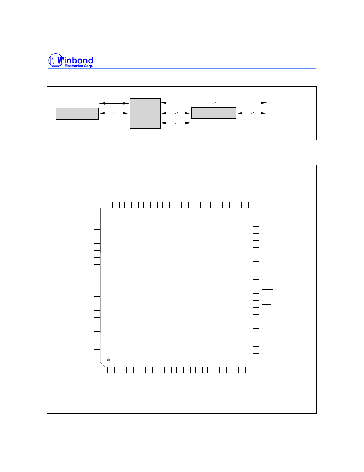
PIN CONFIGURATION
R R
0
DD
81
82
83
84
85
86
87
88
89
90
91
92
93
94
95
96
97
98
99
100
1
2 3 4
RD6RD6+
RD5RD5+
RD4RD4+
AV
RD3RD3+
RD2RD2+
RD1RD1+
AVss
RD0RD0+
DIDI+
CICI+
IMPR II
D D D DVD D D D DD D D D DVD D
V
D
s s
D
s
+ - + - + - + -+ - + - + -
D
55556666777777
D
77777777778
Preequalizer
Port status direct report
VTT D D TT D D TT D D TT D D
s s
-
+
+
6666666666
1234567890123456789
W89C982AF
5 678 9 0
1 1 1 1 1 1 1 1 1
1 2 3 4
5 6 7 8 9 0
1
2 2 2 22 2 2 2 2 2 3
1 2
444 4
-
T
T
P
P
7
6
R
R
P
P
T
T
3
4
T
T
T
P
P
P
5
4
3
R
R
R
VD D
P
P
P
s
T
T
T
5 6 7 8 9
AUI
Twisted-pair
Media
T
P
2
R
V
D
P
D
T
5155555555
234567890
50
TP1RPT
49
TP0RPT
48
AUIRPT
47
XCOLRPT
46
ICRS
45
IDAT
44
IDCLK
43
DVss
42
IJAM
41
DV
DD
40
ICOL
39
IBEN
38
RST
37
TEST
36
DVss
35
X2
34
X1
33
DV
DD
32
PCRS
31
STR
0
P P D D D D D DV
L L
O O
TT
-
L L
+
0 0
V
D
D
+ -V
s
s
ssD D
0 0
+ -TT+ -
D D D D D D D D
V
D D
D
D
1 1
1 1
+ -
+ -
D D D DV MM MM M D
V
TT
D D
D
D
+ -TT+ -
D D
s
s2 2 2 2 3 3 3 3
+ -
10S SIC
OVs
L
s
K
Publication Release Date: November 1996
- 3 - Revision A1

Preliminary W89C982AF
ICRS
PIN DESCRIPTION
NETWORK INTERFACE PINS
NAME NO. I/O DESCRIPTION
DO+
DO-
DI+
DI-
CI+
CI-
DT0+
to
DT7+
DT0to
DT7-
DD0+
to
DD7+
DD0to
DD7-
4
3
98, 97 I AUI Receive Input:
100, 99 I AUI Collision Input:
5, 11, 15,
20, 63, 68,
72, 78
6, 12, 16,
21, 62, 67,
71, 77
8, 13, 17,
23, 60, 66,
70, 75
9, 14, 18,
24, 59, 65,
69, 74
O AUI Transmit Output:
Differential line driver that sends differential signal to Medium
Attached Unit (MAU). These pins require a 270 ohm pull-down
resistor to GND.
Differential receiver that receives the AUI-compliant receive signal
from MAU.
Differential receiver that receives the AUI-compliant collision
signal from MAU.
O Data Positive:
Transmit data driver positive that transmits data on the twisted pair
line. The driver will source or sink 32 mA. The driver is low during idle.
O Data Negative:
Transmit data driver negative that transmits inverted data on the
twisted pair line. The driver will source or sink 32 mA. Driver is low
during idle.
O Delayed Data Positive:
Transmit data driver positive that transmits delayed inverted data
on the twisted pair line. The driver will source or sink 32 mA.
Driver is low during idle.
O Delayed Data Negative:
Transmit data driver negative that transmits delayed data on the
twisted pair line. The driver will source or sink 32 mA. Low during
idle.
RD0+
to
RD7+
RD0to
RD7-
96, 93, 91,
89, 86, 84,
82, 80
95, 92, 90,
88, 85, 83,
81, 79
46 O Inter-IMPR II Carrier Output:
I Twisted Pair Line Receive Positive:
Positive data from the twisted pair line are received by the internal
receiver through this pin.
Twisted Pair Line Receive Negative:
I
Negative data from the twisted pair line are received by the
internal receiver through this pin.
INTER-IMPR II INTERFACE PINS
The inter-IMPR II carrier (an active low on this pin) will be present
when the IMPR II is repeating packets. The IMPR IIs output this
signal to the interface of inter-IMPR II for retransmitting valid
packets or propogating network collision messages to other IMPR
IIs.
- 4 -

Preliminary W89C982AF
IBEN
IBEN
IBEN
ICRS
ICRS
IBEN
ICOL
ICOL
ICRS
ICOL
ICRS
IBEN
ICRS
IBEN
IBEN
RST
RST
Continued
INTER-IMPR II INTERFACE PINS
NAME NO. I/O DESCRIPTION
39 I
40 I
IDCLK 44 IOInter-IMPR II Data Clock:
IDAT 45 I
IJAM 42 I
38 I IMPR II Reset:
MCLK 28 I Management Bus Clock:
Inter-IMPR II interface Enable:
is driven by HUB integrator. The integrator will drive the
low if there is only one IMPR II which outputs
inter-IMPR II interface. The IMPR II that asserts
allowed to transmit valid messages to the IMPR II integrator when
is low.
Inter-IMPR II Collision:
will be driven low when more than one IMPR II
simultaneously output
will not transmit any data to the IMPR II integrator when
low. On this situation the collision messages will still be sent to all
ports of the IMPR II.
IDCLK will drive a 10 MHz clock output when
and
IDCLK will be driven by the IDCLK signal of another IMPR II. If a
dumb hub is used, i.e., no
impedance. This pin is synchronous to IDAT data.
Inter-IMPR II Data:
The IMPR II sends/receives valid packets or inter-port collision
O
messages to/from other IMPR IIs through the IDAT pin in NRZ
Z
format. IDAT is in high-Z state during inter-IMPR II collisions or
when the network is idle. IDAT remains high when there is a
transmit collision in the IMPR II.
Inter-IMPR II IJAM:
IJAM is driven low when a valid packet is being sent. IJAM is
O
driven high when IDAT carries a collision message (i.e., always
Z
high or always low). IDAT = 0 indicates a multiport collision and
IDAT = 1 indicates a single port collision condition.
During inter-IMPR II collisions or when the network is idle, IJAM
should be in high-Z state.
MANAGEMENT BUS PINS
The IMPR II will be forced into its initial state when
low.
The management data are clocked by MCLK serially. The rising
edge of MCLK will latch the data into or out of the IMPR II.
is driven. If
to the IMPR II integrator. The IMPR II
is not asserted and
is present, this pin is in high
to the
will be
is
is asserted
is driven,
is driven
Publication Release Date: November 1996
- 5 - Revision A1

Preliminary W89C982AF
Continued
MANAGEMENT BUS PINS
NAME NO. I/O DESCRIPTION
MSI 27 I Management Data in:
The management command is serially clocked into IMPR II by
MCLK.
MSO 29 O Management Data Out:
The network status or the internal management status of the IMPR
II is serially read out from MSO whenever the IMPR II receives a
status read command.
TEST 37 I IMPR II Test Mode:
This pin should be tied high during test mode and tied low during
normal operations.
PCRS 32 O Network Port Carrier Sense:
The carrier sense signals for the IMPR II's internal logic from the
AUI port and eight TP ports are serially sampled and output
through PCRS. The output bits are stream synchronized to X1
clock.
STR 31 O Network Port Carrier Sense Strobe:
The serial bit stream on PCRS can be latched by an external latch
using the STR signal. The STR goes high for two X1 clock cycles
after the nine carrier sense bits are output through PCRS.
X1 34 I System Clock Input:
An external 20 MHz system clock source is connected to this pin to
provide the operating clock. For crystal applications, a 20 MHz
crystal may be connected across pins X1 and X2.
X2 35 O Crystal Clock Feedback:
Pin X2 should be left floating when an external clock source is
used.
PORT STATUS DIRECT REPORT INTERFACE PINS
M1
M0
XCOLRPT
25
26
47 O Collision Status Direct Report Output: Whenever a collision event
I Port Status Direct Report Select Pins:
These two pins control the output status of the port status pins.
Four output states can be selected by M1, M0:
TP Link/Activity Partition Polarity error Utilization
AUI COL/Activity Partition Loopback error Utilization
M1 0 0 1 1
M0 0 1 0 1
occurs, this pin is active high. This pin drives a TTL data buffer,
which directly drives an LED.
- 6 -

Preliminary W89C982AF
Continued
PORT STATUS DIRECT REPORT INTERFACE PINS
NAME NO. I/O DESCRIPTION
AUI RPT
TP0 RPT
TP7 RPT
VDD 10, 19, 52,
VSS 7, 22, 53,
AVDD 87 I TP Receive Power Supply: +5V DC power supply.
AVSS 94 I TP Receive Ground: Grounding pins.
PLL -
VDD
PLL VSS
48 O AUI Port Status Direct Report Output: This pin outputs the AUI port
status selected by M0/M1. This pin drives a TTL data buffer, which
directly drives an LED.
49−51,
54−58
64, 73
61, 76
1 I PLL Power Supply: +5V DC power supply.
2 I PLL Ground: Grounding pins.
O TP Port Status Direct Report Output: These pins output the TP
port status selected by M0/M1.
These pins drive a TTL data buffer, which directly drives an LED.
POWER GROUND PINS
I Power Supply for TP Transmit/Port Status Pins: +5V DC power
supply.
I Ground for TP Transmit/Port Status Pins.
This pin should be decoupled with a 22 µF capacitor and kept
separate from other power and ground planes.
This pin should be decoupled with a 22 µF capacitor and kept
separate from other power and ground planes.
DVDD 33, 41 I Digital Power Supply: +5V DC power supply.
DVSS 30, 36, 43 I Digital Ground: Grounding pins.
Publication Release Date: November 1996
- 7 - Revision A1
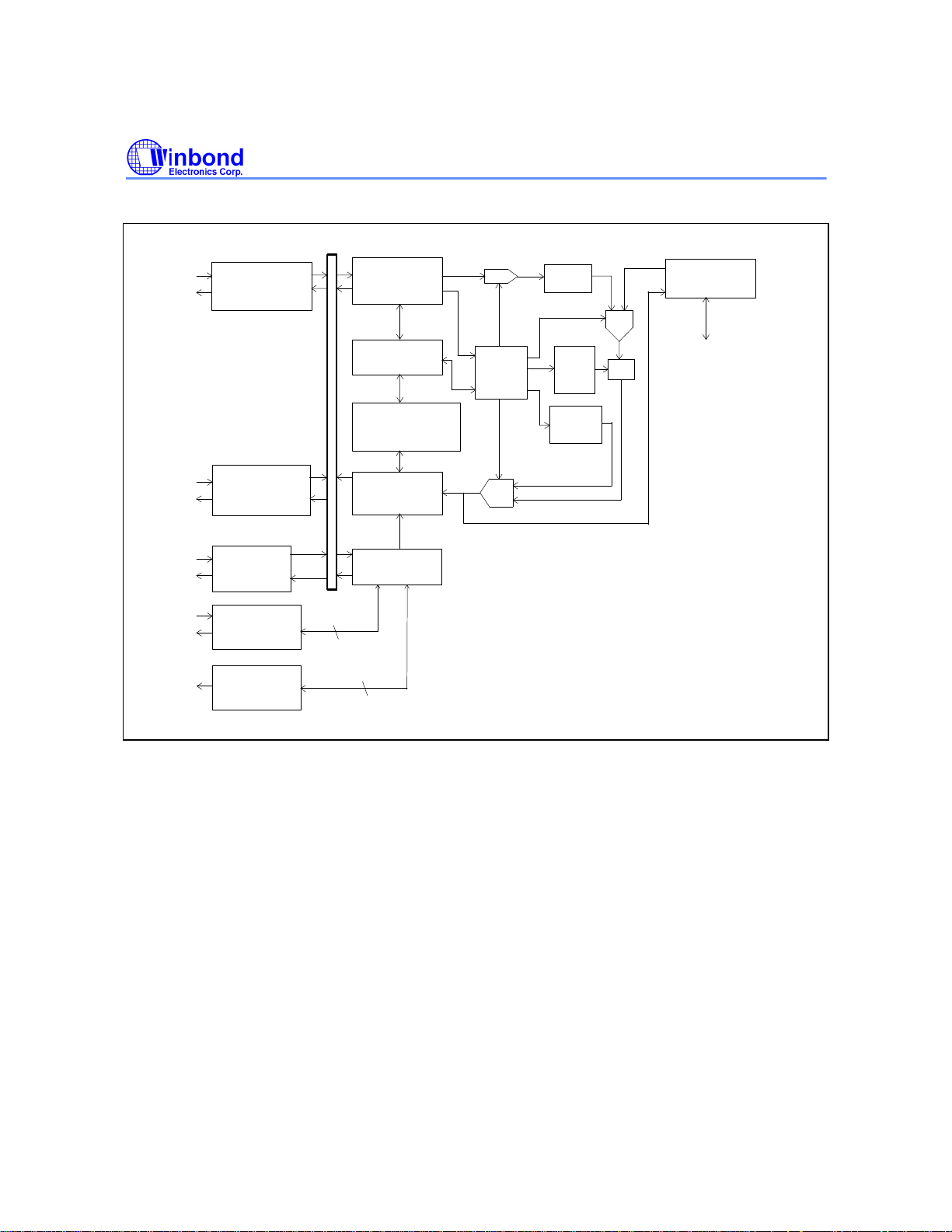
BLOCK DIAGRAM
Preliminary W89C982AF
Twisted Pair Line
Transceiver 1
.
.
.
.
.
.
Twisted Pair Line
Transceiver 8
AUI
Interface
Management
Interface
Port status
direct report
Port Partition/
Reconnection
Logic
Timer and
Counters
Jabber lockup and
Fragment extension
Logic
Encoder and
Transmitter
Logic
Management
Logic
Rx MUX
Main state
Machine
and
Glue logic
Tx MUX
PLL
Decoder
FIFO
Control
Logic
Preamble/
JAM
Generator
MUX
FIFO
Inter-IMPR II
Interface
FUNCTIONAL DESCRIPTION
The Integrated Multiple Port Repeater II implements the functions stipulated in the IEEE repeater
specifications, the functions specified by 10BASE-T standards, and functions for network
management. It provides an Inter-IMPR II interface to allow implementation of a repeater set with
more network ports. The block functions of the IMPR II are described below.
AUI Interface and Twisted Pair Line Transceiver
The AUI provides an interface for an external Medium Attached Unit (MAU) connected to the IMPR II.
The IMPR II can be used to connect a 10BASE2 or 10BASE5 Ethernet to a 10BASE-T Ethernet via a
coaxial transceiver. The Twisted Pair Line Transceiver provides the interface used to connect IEEE
802.3 LAN stations (Data Terminal Equipment, or DTEs) into Ethernet networks constructed from
twisted pair media. The Twisted Pair Line Transceiver also contains a link test function and
autopolarity reversal function for wiring detection.
Link Test Function
The link test function of the TP port is used to check whether the TP port is linked to an active TP
port. The TP port will enter link fail state if it does not receive any packets or link test pulses for more
than 60 mS, until it receives either six consecutive link pulses or a packet. When the TP port is in link
- 8 -

Preliminary W89C982AF
fail state, the IMPR II will not transmit any signal (packets or link pulses) on the TP port and the first
input packet will not be retransmitted. The IMPR II will transmit link test pulses to any TP port after
the transmitter of the TP port has been inactive for more than 16 mS after the TP port enters link
good state. The link test function of the TP port is user-programmable using the management
functions of the IMPR II. The TP port is forced into link good status if the link test function is disabled.
The link test function is enabled by default each time the IMPR II is reset.
Automatic Polarity Reversal Function
The automatic polarity reversal function checks the polarity of the input data packets or link pulses.
The polarity of the TP port will be set to negative when the polarity of the first input packet or the first
three consecutive link pulses following reset or following entry of the TP port into link fail state are
detected to be negative. Once the polarity of the TP port is set to negative, all consequent input
packets will be retransmitted with data that are inverted with respect to the input packet after the TP
port enters link good state. If the polarity of the TP port is not set to negative, all input packets will be
retransmitted without any modification of the data polarity. Once the polarity of the TP port is
determined, the polarity of this port will not be updated until the IMPR II is either reset or re-enters link
fail state, regardless of whether the automatic polarity reversal function is disabled or enabled. The
automatic polarity reversal function is user-programmable using the management functions of the
IMPR II and is enabled by default each time the IMPR II is reset. The default status of polarity is
"correct" when the IMPR II is in reset state.
Port Partition/Reconnection Logic
The port partition/reconnection logic implements the segment partitioning algorithm and the segment
reconnection algorithm. These algorithms are defined by IEEE specifications and are used to protect
the network from malfunctioning segments. There are nine partition/reconnection machines in an
IMPR II. Each port partition reconnection machine controls an individual network port.
A network port will be partitioned by the IMPR II when either of the following conditions is detected:
(1) A collision condition exists continuously for a period of up to 1024 bit times.
(2) Thirty-two consecutive collisions occur.
A collision condition is defined as more than two network ports attempting to transmit simultaneously
or as a receive collision from the AUI.
The IMPR II can reconnect a partitioned network port using algorithms selected by programming the
management logic. The following are the two reconnection algorithms:
(1) Standard reconnection algorithm:
A partitioned network port will be reconnected if a data packet longer than 512 bit times is
retransmitted to or received from that port without collision.
(2) Alternative reconnection algorithm:
A partitioned network port will be reconnected if a data packet longer than 512 bit times is
retransmitted to that port without collision.
The reconnection algorithms for all the TP ports and the AUI port are programmed individually;
however, all the TP ports use the same algorithm. The standard algorithm is selected by default each
time the IMPR II is reset.
Port Status Direct Report Function
Publication Release Date: November 1996
- 9 - Revision A1
 Loading...