

Winbond Electronics W83602R, W83601R Datasheet

W83601R/602R
Winbond SMBus GPI/O
W83601R/602R
PRELIMINARY
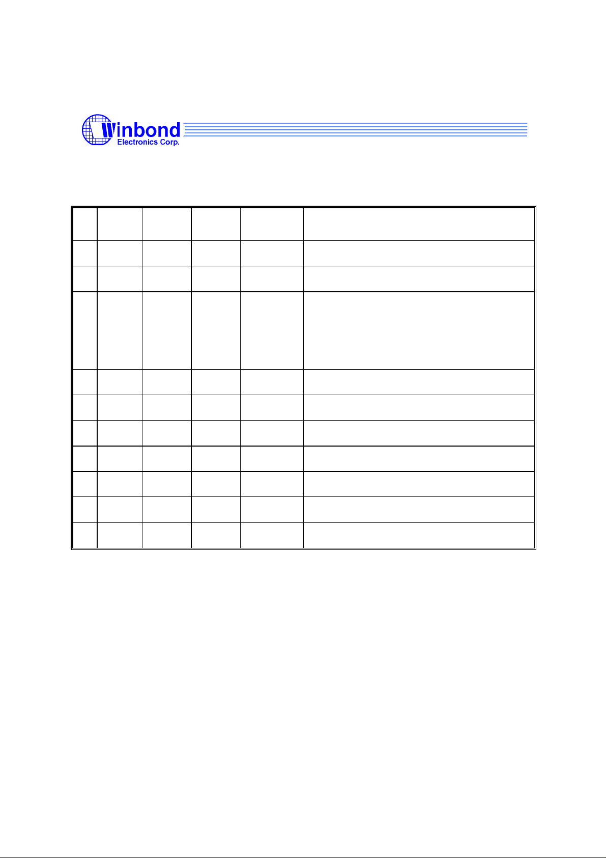
W83601R/602R Data Sheet Revision History
Pages Dates Version Version
on Web
1
2
3
4
5
6
7
8
9
n.a. n.a. All the version before 0.30 are for internal use.
n.a. 99/8 0.3 n.a. First publication.
P.4,5
P.6
P.10
P.13
P.10 99/9 0.32 n.a. CR15 bit 3 description.
99/8 0.31 n.a. Change Pin Description of W83601R pin 3,4,5.
Main Contents
Change Pin Description of W83602R pin 3,4.
Update Register Table.
CR16 is a reserved register. Please ignore it.
Change INT output description.
10
Please note that all data and specifications are subject to change without notice. All the
trade marks of products and companies mentioned in this data sheet belong to their
respective owners.
LIFE SUPPORT APPLICATIONS
These products are not designed for use in life support appliances, devices, or
systems where malfunction of these products can reasonably be expected to result in
personal injury. Winbond customers using or selling these products for use in such
applications do so at their own risk and agree to fully indemnify Winbond for any
damages resulting from such improper use or sales.
Publication Release Date: Aug. 1999
- 1 - Revision 0.32

W83601R/602R
Preliminary
1. GENERAL DESCRIPTION
The W83601R/602R are general purpose input/output ICs with SMBusTM. W83601R provides 15
GPI/O pins. W83602R provides 9 GPI/O pins and ACPI power control function for STR.
W83601R/602R both provides SMBusTM address setting pins to set the address during power- on
reset or from external reset.
W83601R SMBusTM Address is :
W83602R SMBusTM Address is :
W83601R/602R also provides a interrupt to inform system that a transition occurs on General
Purpose(GP) input pins.
0 0 1 1 A2 A1 A0 R/W
0 0 1 1 0 A1 A0 R/W
2. FEATURES
• SMBus compliance with 3.3V voltage levels
• Two ports GPI/O which provides more flexibility
• Issue interrupt to notify system that a event occurs
• GP output can be level or pulse mode
• Interrupt output can be level or pulse mode
• Internal power-on reset or external RST# pin reset
• Programmable POWER LED output
• ACPI power management for Suspend To Ram (STR) (only for W83602R)
3. PACKAGE
• 20-pin SSOP
Publication Release Date: Aug. 1999
- 2 - Revision 0.32
4. KEY SPECIFICATIONS
• Supply Voltage 5V
• Operating Supply Current 1 mA typ.
• Operating Temperature 0 - 70 °C
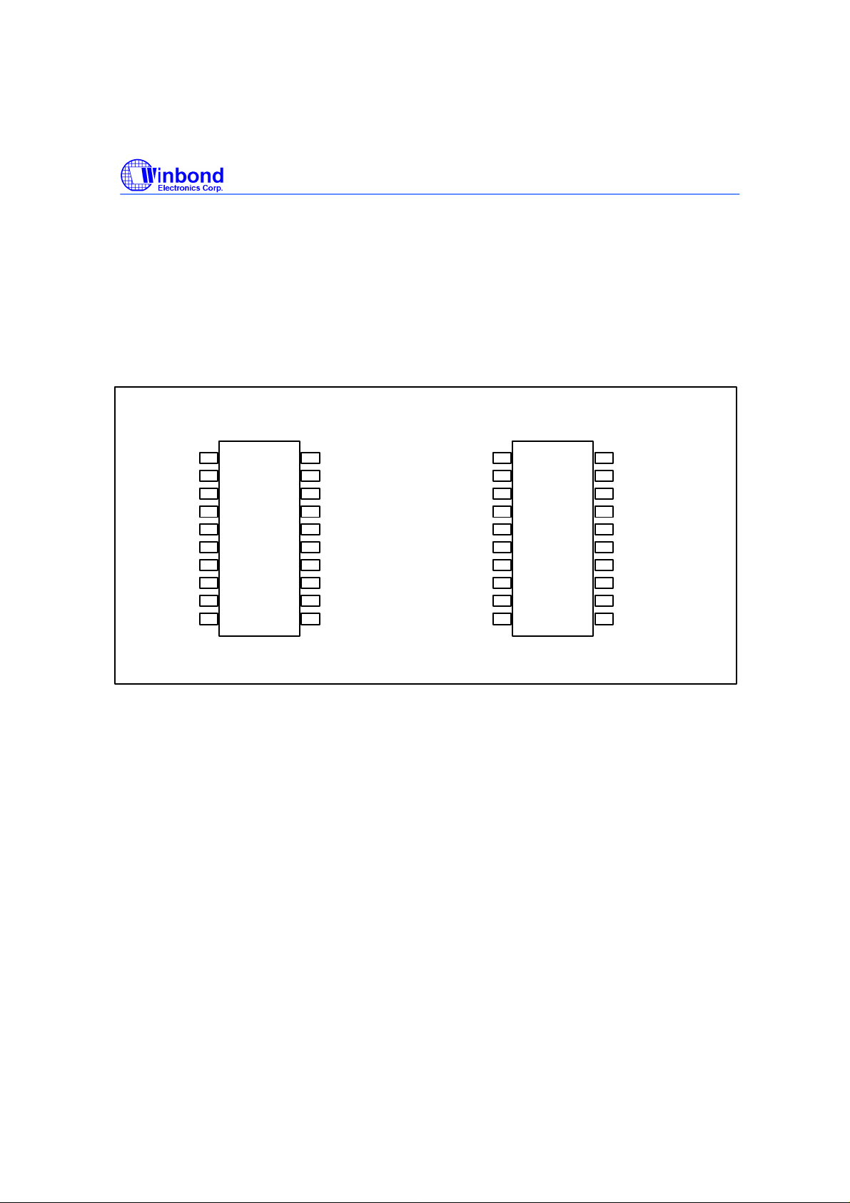
5. PIN CONFIGURATION FOR W83601R/602R
W83601R/602R
Preliminary
SCLK
SDAT
GP20/A0
GP21/A1
GP22/A2
GP10
GP11
GP23
GP24
VSS
W83601R
1
2
3
4
5
6
7
8
9
10
20
19
18
17
16
15
14
13
12
11
20SSOP 20SSOP
VDD
RST#
GP17/INT
GP16
GP15
GP14
GP13
GP12
GP26/INT
GP25
SCLK
SDAT
GP20/A0
GP21/A1
CTL3VSB
GP10
GP11
CTLSTRV
S5IN#
VSS
W83602R
1
2
3
4
5
6
7
8
9
10
20
19
18
17
16
15
14
13
12
11
VDD
RST#
GP17/INT
GP16
GP15
GP14
GP13
GP12
PWCTLIN#
PS_ON#
Publication Release Date: Aug. 1999
- 3 - Revision 0.32
W83601R/602R
Preliminary
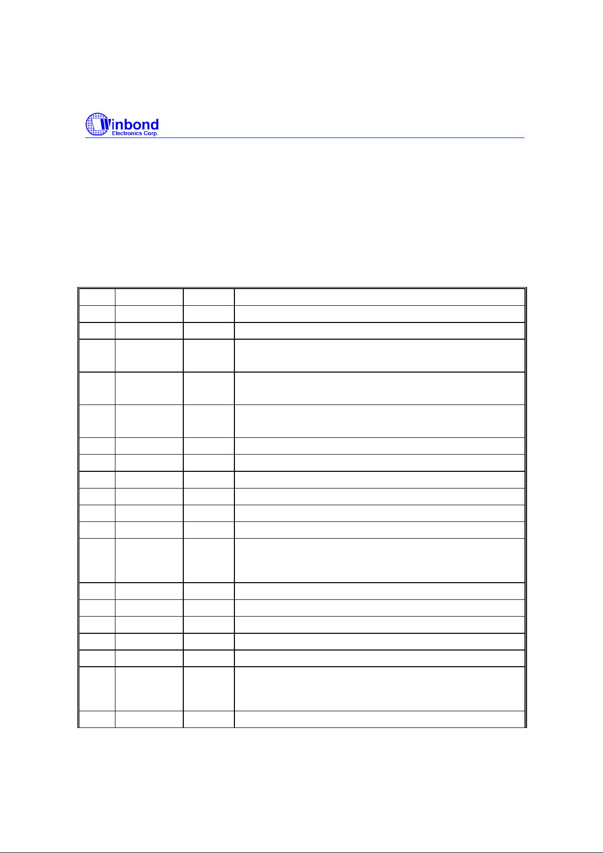
6. PIN DESCRIPTION
Note: Please refer to Section 13.2 DC CHARACTERISTICS for details.
I/OD
- TTL level bi-directional pin open drain output with 12 mA sink capability
24t
I/O
- TTL level bi-directional pin with 24 mA source-sink capability
24t
INt - TTL level input pin
INtd - TTL level input pin with internal pull down resistor
INts - TTL level Schmitt-trigger input pin
W83601R UNIVERSAL GENERAL PURPOSE I/O PORT FOR I2C BUS
PIN SYMBOL I/O FUNCTION
1 SCL INts SMBus Clock. (I2C clock)
2 SDA I/OD12 SMBus bi-directional Data.(I2C data)
3 GP20
A0
4 GP21
A1
5 GP22
A2
6 GP10 I/OD24 General Purpose I/O default input.
7 GP11 I/OD24 General Purpose I/O default input.
8 GP23 I/OD24 General Purpose I/O default input.
9 GP24 I/OD24 General Purpose I/O default input.
10 VSS PWR Ground Pin.
11 GP25 I/OD24 General Purpose I/O default input.
12 GP26
INT
13 GP12 I/OD24 General Purpose I/O default input.
14 GP13 I/OD24 General Purpose I/O default input.
15 GP14 I/OD24 General Purpose I/O default input.
16 GP15 I/OD24 General Purpose I/O default input.
17 GP16 I/OD24 General Purpose I/O default input.
18 GP17
INT
19 RST# INts Reset signal input.
I/O
24
INtd
I/O
24
INtd
I/O
24
INtd
I/OD
OD24
I/OD
OD24
General Purpose I/O . This pin is a setting pin for SMBus(I2C)
address bit 0 during power-on reset or RST# pin reset.
General Purpose I/O . This pin is a setting pin for SMBus(I2C)
address bit 1 during power-on reset or RST# pin reset.
General Purpose I/O . This pin is a setting pin for SMBus(I2C)
address bit 2 during power-on reset or RST# pin reset.
General Purpose I/O default input.
24
Auto-generate Interrupt signal when detetecting a transition on
GPI inputs. This interrupt is either on pin12 or pin18.
General Purpose I/O default input.
24
Auto-generate Interrupt signal when detetecting a transition on
GPI inputs. This interrupt is either on pin12 or pin18
Publication Release Date: Aug. 1999
- 4 - Revision 0.32
W83601R/602R
Preliminary
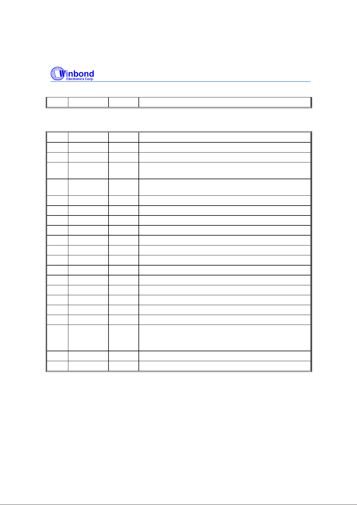
20 VDD PWR Power Pin.
W83602R UNIVERSAL GENERAL PURPOSE I/O PORT FOR I2C BUS & ACPI
POWER CONTROL
PIN SYMBOL I/O FUNCTION
1 SCL INts SMBus Clock. (I2C clock)
2 SDA I/OD12 SMBus bi-directional Data.(I2C data)
3 GP20/A0 I/O24 General Purpose I/O. Power on setting for SMBus(I2C) address
bit 0.
4 GP21/A1 I/O24 General Purpose I/O. Power on setting for SMBus(I2C) address
bit 1.
5 CTL3VSB OD24 Control 3VSB and 3VCC power source for ACPI features.
6 GP10 I/OD24 General Purpose I/O default input.
7 GP11 I/OD24 General Purpose I/O default input.
8 CTLSTR OD24 Suspend to RAM power control output.
9 S5IN# INt S5# signal input.
10 VSS PWR Ground Pin.
11 PS_ON# OD24 ATX power power on_off control.
12 PWCTLIN# INt Connected to W83627F/HF power control output .
13 GP12 I/OD24 General Purpose I/O default input.
14 GP13 I/OD24 General Purpose I/O default input.
15 GP14 I/OD24 General Purpose I/O default input.
16 GP15 I/OD24 General Purpose I/O default input.
17 GP16 I/OD24 General Purpose I/O default input.
18 GP17
INT
19 RST# INts Reset signal input.
20 VDD PWR Power Pin.
I/OD
OD24
General Purpose I/O default input.
24
Auto-generate Interrupt signal when detetecting a transition on
GPI inputs.
Publication Release Date: Aug. 1999
- 5 - Revision 0.32
 Loading...