

Winbest PCP User Manual
by
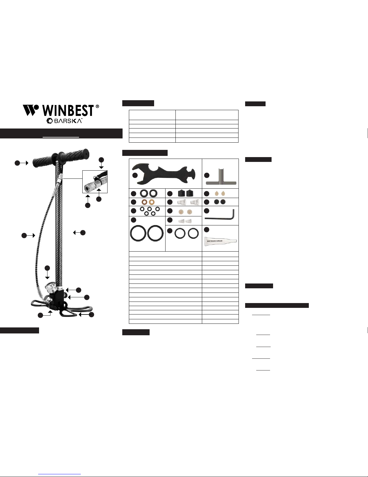
PCP Pump
A - Rubber Grip
B - Pump Barrel
C - Base Plate
D - Pressure Gauge
E - Moisture Filter
F - Hose
G - Quick Connector
H - Test Plug
I - Bleed Valve
J - Folding Base Plate
K - Belt
A
B
F
D
E
J
I
C
H
G
Length:
Weight:
Maximum Pressure:
Time:
Output Nut:
Quick Connector:
25.6 inches / 650mm retracted
44.1 inches / 1120mm expanded
5.29 lbs / 2.4kg
4500 psi / 310 bar
At 200 bar 2 hours continuously
M10x1
8/16” / 8mm size
Specifications
Included Accessories
Item
Special Wrench
T Spanner
High Pressure Stem Sealing Ring
High Pressure Piston Ring
O-Ring
Other Tube Piston Ring
Check Valve
Check Valve Spring
Sealing Gasket of Bleed Valve
High Pressure Piston Spring
Low Pressure Piston Ring
High Pressure Spool Valve
Inlet Hole One Way Seal Ball
Allen Spanner
Maintenance Grease
Qty
1
1
2
2
5
2
2
2
2
2
2
2
2
1
1
1.
2.
3.
4.
5.
6.
7.
8.
9.
10.
11.
12.
13.
14.
15.
1 2
3
4
11
5
6
7
8
9
12
13
14
15
10
Install
Open the package and inspect all items. Read the instructions
before use. Familiarize yourself with proper operational method.
The wrong operation can be harmful to the user and may damage
the pump.
Loosen the belt on the pump, unscrew the bleed valve, pump up
and down 10 times to empty the pump. Tighten the bleed valve
and pump up to 200 bar (usually 6 times) then wait for 2 minutes
under 200 bar state to check whether there is leakage (check
pressure gauge needle). The best way to check for a leakage
point is to place the pump underwater.
Operation
1. Remove test plug from pump by pressing down on silver ring.
2. Before pumping, be sure the hose has no knots. Pull
and push the pump quickly. You will feel resistance when the
pressure in the container reaches 100 bar, this is normal.
3. Connect the pump to the container according to the
container’s instructions.
Note: Before starting to fill the container, read the instruction
booklet about that container to ensure the correct amount of
pressure.
4. Check that the bleed valve is tightened correctly. Keep the
pump steady by standing on the base of the pump. Pull
and push the pump quickly to inflate the gas.
5. Open the bleed valve screw to relieve pressure in the hose.
Make sure the pressure gauge needle is at 0 before
disconnecting the container.
Note: You could directly open the bleed valve if the container
has a unidirectional valve. If your container does not have
a unidirectional valve, first turn off the valve to release residual
gas in the pump barrel and hose when filling the container. It is
normal to find small amounts of gas and water leaking from
the bleed valve.
6. Disconnect the pump from the container according to the
container’s instructions.
High Piston
1. First to screw the nut off.
2. Use T spanner to take the pole out.
Common Problems and Solutions
Problem 1: The needle of pressure gauge does not move or
moves very slowly when pumping. Generally speaking a 0.5L
standard container should cause the needle to reach the 200 bar
when pumped for 420-450 times.
Reason: The needle has not moved or is moving very slowly is
because of a leak.
Solution: To confirm leak place pump underwater to find a
leakage point.
Problem 2: In the process of pumping, it pulls heavy and pump
automatically pumps down
Reason: The stage 3 piston has a malfunction
WARNING
DO NOT disassemble any joint when there is residual gas, it is
dangerous to take apart the joint in this situation.
DO NOT put your hand near the air vent or point it at people when
you release the bleed valve screw, it can cause serious damage.
DO NOT add lubricating oil to the pump. Use appropriate grease
as necessary.
Parts of the Pump
K
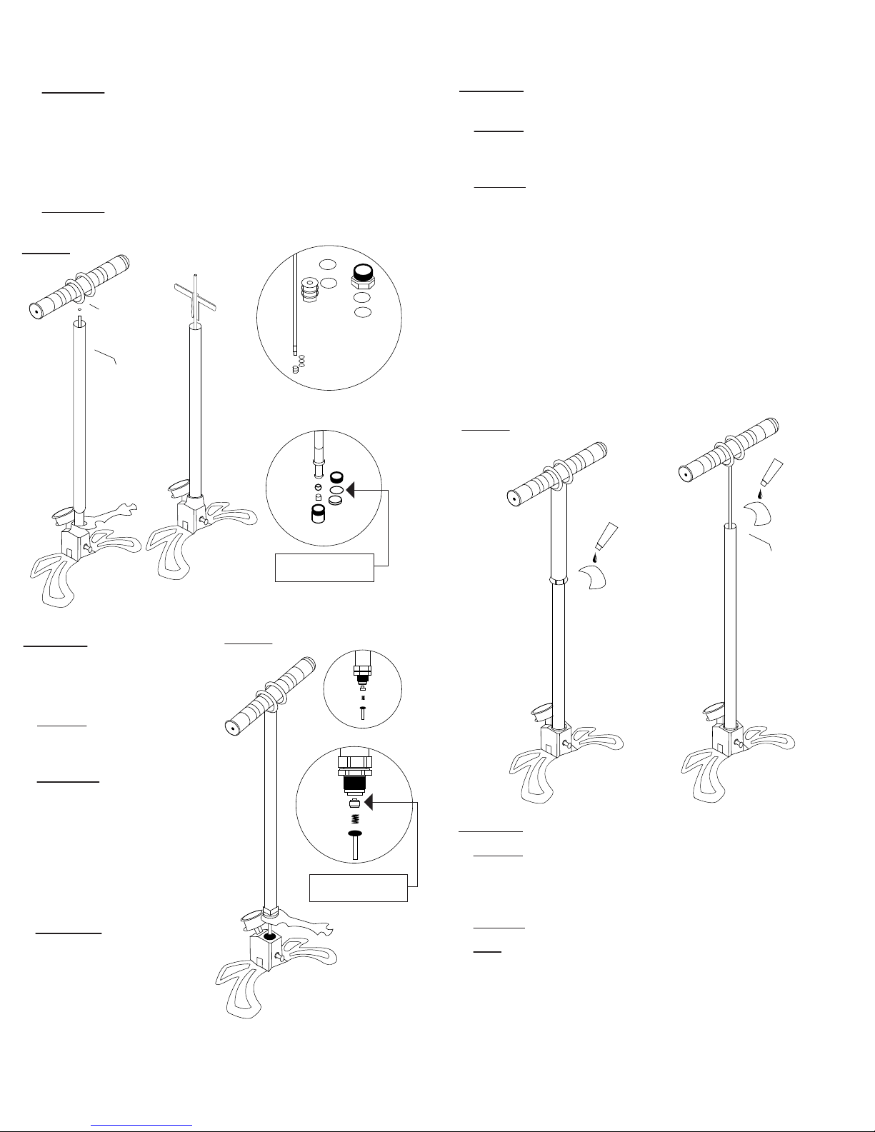
Solution 1: Open the bleed valve to take apart the tube and the
connecting screw which is on the top of the pump barrel. Fill
the tube with water or silicon oil (not included), then
reassemble the pump, remove test plug and continuously
pump (10 times). When the pump automatically sucks back
remove any debris from the valve and replace the o-ring.
See image 1.
Solution 2: Take apart the Level 3 piston set to find the
leakage or change the o-ring.
Problem 3: In the process of
pumping the pull is very light but
pushing down has resistance or
it will automatically run up.
Reason: Setup instructions
may have not been followed
correctly.
Solution 1: Add lubricating oil
or silicone oil, do not release
excess gas in high pressure,
this can cause a gas
explosion if the pressure is
above 150 bar resulting in a
damaged check valve or a
carbon deposit in the
check valve.
Solution 2 : Clean or
replace the check valves
when the pump automatically
runs up. Use the included
special wrench to open the
base to replace or clean
the check valve. See image 2.
Problem 4: The resistance builds up when pulling and pushing
the pump.
Reason: Dust may have accumulated on the seals surface and
is interfering with the self-lubricating function. The pump now
requires maintenance.
Solution: Disassemble pump, apply maintenance grease on a
cloth, then dry wipe all sealing rings, cylinder surfaces, 5mm
solid core rod and the whole external high-pressure piston. After
assembly, ensure that all sliding surfaces have a thin layer of
maintenance grease.
To test if there is enough lubrication pour out the excess
maintenance grease and the base absorption ball inside. Empty
the pump by pumping it about 50 times to discharge excess
maintenance grease. Clean the base adsorption ball and check
valve with detergent and water. Make sure items are dry and
place them back into the base. Use the test plug to test the
pump according to problem 3. When you feel a heavy pull
during the inflation process, apply a small amount of
maintenance grease. See image 3.
Problem 5: The pressure gauge needle is not at zero.
Reason: Lubricating oil and silicone oil was not added or
drained properly causing an explosion under the pressure of
150 bar or higher. Damage may also been caused
during transportation.
Solution: Pressure gauge needs to be replaced.
Note
You will hear a hissing and water sound when you release
residual gas in the pump and hose. Normally a small volume of
gas is released, if the volume of the gas is large the check valve
may not work properly or the check valve is not fastened well. If
the problem still exists contact the manufacturer.
Image 2
Image 1
Image 3
O-Ring
Accessory Number 5
Check Valve
Accessory Number 7
 Loading...