

Win4NET H.264 8-Channel Mobile DVR User Manual

User’s Manual
H.264 8-Channel Mobile DVR
▪ H.264 8-Ch. Mobile DVR
▪ Anti Shock & Vibration control
▪ Built-in Heating System
▪ 2.5” Mobile HDD & SD Card
▪ GPS, G-Sensor
1
Preface
We welcome you as a new user of the world's best digital video recorder (DVR) and leading
Digital Video Surveillance System. For best use of this product, read this manual carefully and
keep this manual close to your hand.
Copyright/Authentication/Trademark/Limited Warranty
Copyright
Copyright (c)2012. Win4NET. All rights reserved. All contents and pictures cannot be copied
without permission.
Authentication
CE, FCC, KCC
Trademark
Ethernet(TM) is a trademark of Xerox Corporation.
Microsoft(TM), MS-DOS(TM), Windows(TM logo), Windows(TM) and Windows NT(TM) are a
trademark of Microsoft Corporation, used in the United States and elsewhere.
Limited Warranty
• The manufacturer, importer and agent shall not be responsible for accidental damage (including
injury) and other damage caused by inappropriate use or operation of this product.
• The information in this manual is prepared based on the current specifications of this product.
The manufacturer would add new functions and continue to upgrade the product with new
technology. All specifications can be subject to change without prior notice.
Cautions
We strongly recommend that users read all safety cautions carefully before operating the
product and safe operation. Following signals contain critical safety information, they must be
fully complied with. The cautions are categorized into Danger, Warning, Caution and Important.
Risk of death or serious injury.
This is the highest priority danger warning.
Risk of serious or less degree of injury.
May also cause damage to the product or to property.
Risk of minor injury or damage.
Requirements or limitations regarding operation. Users are
recommended to read the relevant details carefully so as to
operate the product properly and without harm.
The above cautions indicate damage level which could occurred due to inappropriate system use
2
Risk of death or serious injury.
This is the highest priority danger warning.
• RISK OF EXPLOSION IF BATTERY IS REPLACED BY INCORRECT TYPE. DISPOSE OF USED
BATTERY ACCORDING TO THE INSTRCTIONS.
• THIS EQUIPMENT IS INDOOR USE AND ALL THE COMMUNICATION WIRINGS ARE LIMITED TO
INSIDE OF THE BUILDING.
• Please connect the power cord only to the type of AC outlet indicated in the manual or product
specification. If connected to other types of power outlet, fire and electric shock may result.
• Do not expose the product to moisture and dampness. Doing so may result in fire and electric
shock.
• Do not place heavy objects on top of the power cord. Damage to the power cord may result in
fire and electric shock.
• Do not place containers with liquid or small metal objects on top of the product. Liquid or small
metal objects getting into the unit may lead to fire and electric shock.
• Do not score, bend, twist, pull or heat the power cord. Damage to the power cord may lead to
fire and electric shock.
• Do not remove the top casing of the product. Doing so may result in electric shock. If internal
examination and maintenance are deemed necessary, contact the authorized system vendors
or installers.
• Do not modify the product in any way. Doing so may lead to fire and electric shock.
• In case of lightning, immediately turn off the power switch and remove the power cord from
the power outlet. Failure to do so may result in fire and electric shock.
• Please use only the power cord supplied with the product. Use of other power cords may result
in fire and electric shock.
• In case of smoke, smell or noise, immediately turn off the power switch and remove the power
cord from the power outlet. Continued operation of the product may result in fire and electric
shock. Request a maintenance service from the authorized system vendors or installers.
• If the product is dropped or damaged, turn off the power switch and remove the power cord
from the power outlet. Continued operation of the product may result in fire and electric shock.
Users should request a maintenance service from the authorized system vendors or installers.
• Do not touch the product with wet hands. Doing so may result in electric shock.
Risk of serious or lesser degree of injury.
May also cause damage to the product or to property.
• Do not leave the power cord or other cables in passageways. Passers-by may trip and fall.
• Avoid contact with water or beverages. Contact with water or beverages may result in damage
that cannot be repaired.
• In case of lightning, immediately turn off the power switch and remove the power cord from
the power outlet. The product may otherwise be damaged.
• Excessive current from the product and the camera may result in an electric shock. Connect the
power cord to an external device only when the products themselves are disconnected from
their power supply.

3
Risk of minor injury or damage.
• If a foreign substance is stuck to the product, remove it using a soft cloth or tissue. Do not use
chemical agents (thinner, solvent, etc.) to remove the substance.
• Do not operate or store the product in the following places.
- An area that is either too cold or too hot
- An area of high humidity, or in front of an air-conditioner, or in places subject to sudden
temperature changes
- An area where there is excessive dust
- Areas where heat from the product cannot be emitted through both of the product's side
ventilation openings
• Do not place credit cards/telephone cards/bank account books/tickets and other objects with
magnetic properties near the product.
• Static electricity may cause damage to the internal parts of the product. Please remove static
electricity from your body before touching the rear panel and internal electronic parts of the
product.
• If this product is damaged beyond repair or reaches its maximum service life, dispose of it in
compliance with local laws and regulations regarding the disposal of lead and plastic waste.
Requirements or limitations regarding operation. Users are
recommended to read the relevant details carefully so as to
operate the product properly and without harm.
• The product may not work properly if the power source is unstable or and if electric shock
occurs. Make sure the correct rated power is available.
• The product is designed to be proof against electric power failures; however, damage may
occur as a result of power failure. Current data may be damaged or data might not be
recorded. Make sure to use an Uninterruptible Power Supply (UPS).
• Since the product is designed to record video data on the hard disk, an error in the hard disk or
other miscellaneous errors might prevent the product from recording properly. Periodic
maintenance is required for proper operation of the product.
• The product is designed for users to configure their own interface. However a user
configuration error could lead to operation malfunction. This product should be set up by
certified installers only.
• Since the product is connected - and tightly coupled - to exterior accessories (camera, sensor,
LAN, Hard Disk, etc.), there is a risk of malfunction from external causes. Ensure periodic
maintenance by the certified installers.
• Use the rack mounting handle provided with the product for installation.
• In this product, 1 Kbyte equals 1,024 bytes, 1 Mbyte equals 1,048,576 bytes and 1 Gbyte
equals 1,073,700,000 bytes.

4
Contents
Preface ............................................................................................... 1
Cautions ............................................................................................. 1
Contents ............................................................................................. 4
Chapter 1. Introduction ..................................................................... 7
1. Introduction ....................................................................................................... 7
2. General Features ................................................................................................ 7
3. Specification ....................................................................................................... 8
Chapter 2. System Installation ........................................................ 10
1. Package Contents ............................................................................................. 10
2. Installation ....................................................................................................... 11
2-1. Remove Bracket ............................................................................................... 11
2-2. Installation ....................................................................................................... 11
2-3. Connection ...................................................................................................... 13
2-3-1 Front ...................................................................................................... 13
2-3-2 Rear panel .............................................................................................. 15
2-3-3 Main Unit IO Box/Control Box connection .......................................... 16
2-3-4 IO BOX ................................................................................................... 16
2-3-5 CONTROL BOX ........................................................................................ 19
3. Cautions............................................................................................................ 20
1. Basic Operation ................................................................................................ 21
1-1. Remote controller use ....................................................................................... 21
1-2. Turning on the System ...................................................................................... 23
1-3. Status Bar ........................................................................................................ 23
1-4. OSD Icons ....................................................................................................... 23
1-5. User or Admin Login ......................................................................................... 24
1-6. Main Menu ....................................................................................................... 24
1-7. Popup Menu ..................................................................................................... 26
2. DVR Setup ........................................................................................................ 27
2-1. System ............................................................................................................ 27
2-1-1. MENU > SYSTEM > Information .............................................................. 27
2-1-2. MENU > SYSTEM > Date & Time ............................................................. 28
2-1-3. MENU > SYSTEM > User ......................................................................... 29
2-1-4. MENU > SYSTEM > Quick Setup .............................................................. 30
2-1-5. MENU > SYSTEM > System Log .............................................................. 30
2-2. DEVICE ............................................................................................................ 31
Set configuration of camera, audio, alarm, keyboard and RS232-485(POS/Keyboard) in
this menu. .............................................................................................................. 31
2-2-1. MENU > DEVICE > Camera ..................................................................... 31
2-2-2. MENU > DEVICE > Audio ........................................................................ 32
2-2-3. MENU > DEVICE > Alarm........................................................................ 32
2-2-4. MENU > DEVICE > Keyboard .................................................................. 33
2-2-5. MENU > DEVICE > RS232 & RS485 ......................................................... 33
2-2-6. MENU > DEVICE > Vehicle ...................................................................... 33
2-3. Display ............................................................................................................ 34
2-3-1. MENU > DISPLAY > Display .................................................................... 34
2-3-2. MENU > DISPLAY > VGA ........................................................................ 34
2-3-3. MENU > DISPLAY > CVBS ....................................................................... 35
2-3-4. MENU > DISPLAY > Digital Signage ......................................................... 36

5
2-4. RECORD .......................................................................................................... 37
2-4-1. MENU > RECORD > STORAGE ................................................................ 37
2-4-2. MENU > RECORD > Record..................................................................... 37
2-4-3. MENU > RECORD > Utilities .................................................................... 39
2-5. NETWORK ....................................................................................................... 40
2-5-1. MENU > NETWORK > Address ................................................................ 40
2-5-2. MENU > NETWORK > DDNS ................................................................... 40
2-5-3. MENU > NETWORK > Notification ........................................................... 41
2-5-4. MENU > NETWORK > Transmission ......................................................... 41
2-6. EVENT ............................................................................................................. 42
2-6-1. MENU > EVENT > Sensor ....................................................................... 42
2-6-2. MENU > EVENT > Motion ....................................................................... 43
2-6-3. MENU > EVENT > Video Loss .................................................................. 45
2-6-4. MENU > EVENT > Text-In ....................................................................... 46
2-6-5. MENU > EVENT > System ....................................................................... 48
3. Playback ........................................................................................................... 50
3-1. Go to Time....................................................................................................... 51
3-2. Calendar Search ............................................................................................... 51
3-3. Event Search .................................................................................................... 51
3-4. Text-In Search .................................................................................................. 52
3-5. Backup Data Playback ...................................................................................... 53
3-6. Playback Control .............................................................................................. 53
........................................................................... 53
4. Backup .............................................................................................................. 54
4-1. Backup ............................................................................................................ 54
4-2. Instant Backup ................................................................................................. 55
4-3. Clip Maker........................................................................................................ 55
Chapter 4. Remote Software NEMON .............................................. 56
1. Using NEMON ................................................................................................... 56
1-1. Starting the Software........................................................................................ 56
1-2. Site Set Up ...................................................................................................... 58
1-3. Favorite Set Up ................................................................................................ 60
1-3. Site List Panel .................................................................................................. 61
1-4. Tool Panel ........................................................................................................ 62
1-4-1. DVR Status ............................................................................................. 62
1-4-2. PTZ ....................................................................................................... 62
1-4-3. TEXT-IN ................................................................................................. 63
1-4-4. GPS ....................................................................................................... 63
2. Remote Playback .............................................................................................. 64
2-1. Calendar Search ............................................................................................... 64
2-2. Event Search .................................................................................................... 65
3-3. Text-In Search.................................................................................................. 66
3-4. Saving the recorded data .................................................................................. 67
3-5. Play Backup Data ............................................................................................. 68
3-6. Play Independent HDD Data on PC .................................................................... 69
4. Setup ................................................................................................................ 70
4-1. Nemon Setup ................................................................................................... 70
4-2. Remote Setup .................................................................................................. 74
4-3. Remote Upgrade .............................................................................................. 75
5. Nemon Callback ................................................................................................ 76

6
Appendix A. Remote Access Using I.E. ............................................ 78
Appendix B. How to set DDNS using router ..................................... 79
1. Domain Name Creation ................................................................................. 79
2. Router Configuration ..................................................................................... 81
3. DVR Configuration ........................................................................................ 82
Appendix C. Digital Signage Maker .................................................. 83
1. How to use Digital Signage Maker ........................................................................ 84
a. Select Source Video File ................................................................................ 84
b. Select Output Device .................................................................................... 84
c. Enter Output File Name ................................................................................. 84
d. Select Video Type ......................................................................................... 84
e. Click Start Button .......................................................................................... 84
F. Import Digital Signage File into DVR ............................................................... 85
Appendix D. NEMON Network Archive Instructions ........................ 86
1. Outline ............................................................................................................... 86
2. Feature ............................................................................................................... 86
3. How to use Network Archiver ............................................................................... 87
Step 1) Entering Archiving Site address and following information for a site
registration and log-in. ...................................................................................... 87
Step 2) Selecting a starting point of data for Remote Archiving. .......................... 88
Step 3) Setting performing schedule for Archiving. ............................................. 89
Step 4) Creating Storage Group. (refer to 4-D for the detail) ............................... 90
4. Set Up ................................................................................................................ 91
A. Main Screen ................................................................................................. 91
B. Tool Bar ....................................................................................................... 92
C. Detail Information ........................................................................................ 93
D. Storage Manager .......................................................................................... 95
E. Log .............................................................................................................. 96
F. System Tray .................................................................................................. 96
5. Reference ........................................................................................................... 97
Appendix E. IO Box Installation ....................................................... 98
Appendix F. Connector pin map ....................................................... 99
COMPLIANCE NOTICE OF FCC: ........................................................................... 101
WEEE (Waste Electrical & Electronic Equipment) ............................................... 101
ROHS Compliance ............................................................................................... 101

7
Chapter 1. Introduction
1. Introduction
This product is a professional mobile security DVR with built in most reliable mobile solutions with
cutting edge technologies for all transportation. It’s been designed to endure severe vibration,
shocks and temperatures. Meet the new technology in transportation security with this new
mobile DVR.
This product is H.264 8channel mobile DVR. Our H.264 DVR, compare to MPEG4 based DVR,
provides better compression rate, picture quality, less packet size and DVD level picture quality
and transmit images remarkably with more technology than others.
This is most reliable product ever introduced product and provide best surveillance features.
Our Standard h.264 compression will guide you to new experience to CCTV technology.
2. General Features
• Standard H.264 video compression
• Provide Ultimate reliability with embedded linux System
• Dedicated Database structure for more stability.
• Resolution D1/Half, D1/CIF
• CMS(Central Monitoring System) support
• Easy setup same like DVR GUI.
• Web monitoring, Searching and setup available.
• Own Media Player for backup playback
• Provide dual USB ports for Mouse and external storage.
• Up to 2 SATA HDD support
• 2-way audio
• DVR operation by Keyboard controller
• Text-In and Relay output support
• Whole channel Real time Recording and Playback
• Mobile device support (IPhone and Android support)
• Triple streaming support in recording, Remote and Mobile in different resolution
• Digital zoom
• Compact size for vehicle installation
• Various type of storage support– 2.5” Ext. HDD, SD Card, USB
• Built in GPS – E-Map support
• Industrial standard in Enduring Temperature limit
• Built in power support for camera and monitor.
• Apply military product level test in vibration and shock test.
• I/O Box (Sensor, Alarm, RS232, RS485, Vehicle State, Speed Pulse, G-Sensor, Status LED)
• Event detection through G-sensor in I/O Box
• Control Box (IR input, Emergency Button, Status LED, CVBS Video-Out, Audio-Out)

8
3. Specification
Category
8 channel premium mobile DVR
Video
In
8 Ch
Out
1VGA, 1 BNC (Dual display)
Audio
In
8 RCA (Line Input)
Out
1 RCA (Line output)
Device
Sensor Input
I/O Box - 8 TTL (7+Emergency)
Alarm output
I/O Box - 8 TTL
I/O Interface
I/O Box - RS232 x 2, RS485, USB x 2, Car Speed Pulse, G-
Sensor, Vehicle State
Display
Speed
Realtime
Resolution
720 x 480 (NTSC), 720 x 576 (PAL), 800 x 600 (VGA)
Split mode
1, 4, 6, 9, PIP, Digital zoom
Recording
Compression
Hardware H.264 codec
Speed/
Resolution
240fps@CIF(NTSC)
200fps@CIF(PAL)
120fps@Half D1(NTSC)
100fps@Half D1(PAL)
60fps@D1(NTSC)
50fps@D1(PAL)
Picture Quality
Very High, High, Standard, Low
Mode
Time-lapse, Event, Time & Event, Emergency (Panic)
Playback
Display
1, 4, 6, 9, Digital zoom
Search Mode
Calendar Search, Event Search, Text-In Search, Go to Time
Playback Mode
Multi Channel Normal & Reverse Play,
RW & FF ( x2, x4, x8, x16, x32), Frame to Frame, Pause
Map
Google Map Interlock
Network
Interface
Ethernet (10/100 Base)
Protocol
TCP/IP, HTTP, DHCP, ADSL(PPPoE), RTP/RTSP
Application
Realtime, Playback, Setup, Remote alarma (callback, E-mail),
E-Map, Live tracking
Web browser
Internet Explorer7 or higher
Mobile
iPhone, Android Phone(Real Streaming)
Storage
SATA HDD(x1) or SSD , SD Card
(HDD RACK: Support External Storage function)
Backup
External HDD(USB) and USB memory
Control
USB mouse,
IR remote controller, Joystick controller, Control Box
OSD
Graphic User Interface (Multi language)
Approval
FCC, CE, KCC, E-mark
ROHS
ROHS Compliance
Power consumption
DC 12 - 30V,
Safety Shutdown mode, Input Power Check

9
Operating Temp.
-20°C ~ 40°C / -4°F~104°F
Integrated Heat circuit
Operating humidity
0%~80% / non-condensing
Dimension
System
225.5(W)x59(H)x242.7(D)mm /
8.87(W)x2.32(H)x9.55(D)inch
I/O Box
155(W)x44(H)x70(D)mm /
6.1(W)x1.73(H)x2.75(D)inch
Control Box
121(W)x32(H)x75(D)mm /
4.76(W)x1.25 (H)x2.95(D)inch
Weight
System
2.58Kg / 5.68 lbs (with HDD)
I/O Box
0.36Kg / 0.79 lbs
Control Box
0.2Kg / 0.44 lbs
10
Chapter 2. System Installation
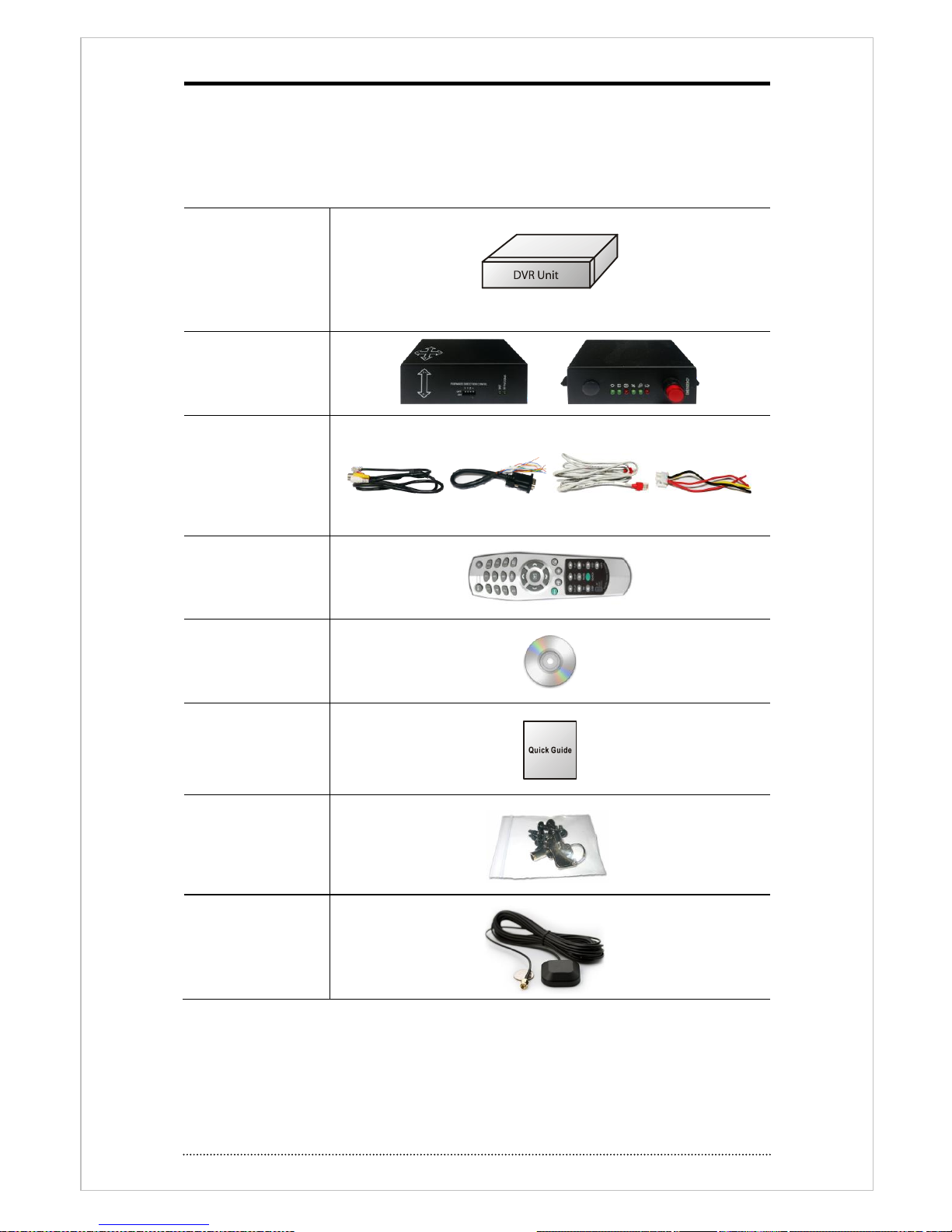
1. Package Contents
The following components are included in product box
DVR unit
Sensor box & Control
Box.
Cables
8e RJ45 cables for
Video
4ea RS232 cables
3ea RJ45 cables
1ea power cable
Remote controller
and batteries.
CD
(User manual and
Network Software)
Quick Guide
Screws and Key for
HDD rack.
GPS Antenna
(Option : SMA type
connector)
11
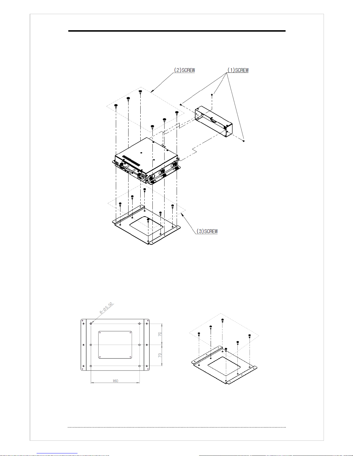
2. Installation
2-1. Remove Bracket
- Take out product from box and remove brackets as above
- Remove screw on rear cover to connect cables. (process (1))
- Remove 6 screws to dis-assemble main unit and bracket. (process (2))
2-2. Installation
- Fix this bracket on the place where you install. Use 6 screws.
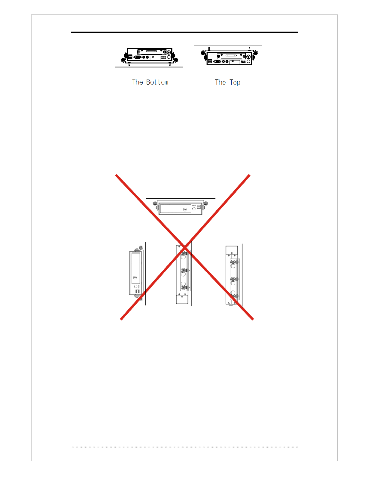
12
- Installation on the bottom : fix both brackets (on DVR unit and mount bracket) and fix with 6
screws.
- Installation on the top : fix the mount bracket on the ceiling first and fix DVR unit with bracket.
Notice
: Installation as follows would cause HDD operation. Attach screw with 12~15Kgf.
( Except on SSD use)
13
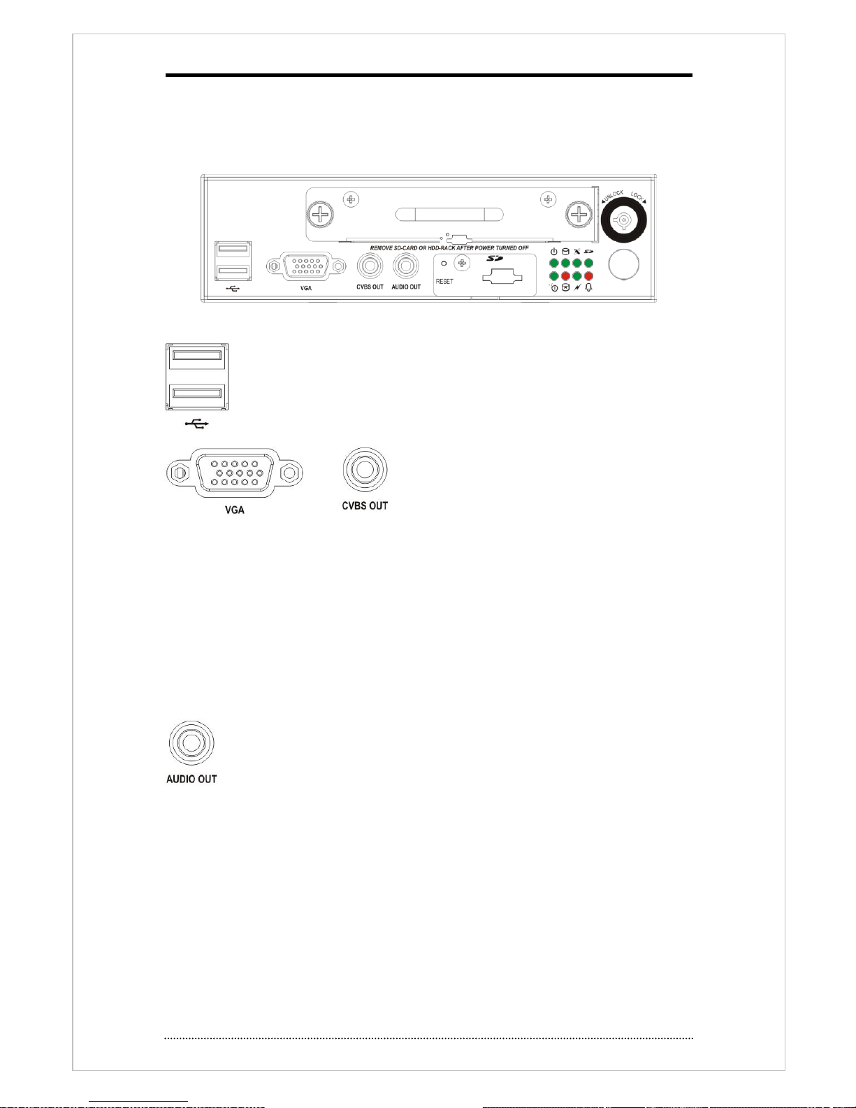
2-3. Connection
2-3-1 Front
Following picture shows the front and rear of this product.
USB
2 usb ports is used for Backup, Ext. HDD connection for System upgrade,
Flash memory and mouse. Connect mouse on the port with picture.
Video output
Connect VGA and CVBS monitor. This DVR provide
same image output on VGA and composite monitor.
One monitor views live image and the other one
views live or playback. Dual display feature provides
provide easy and convenient feature to user.
Notice
: Default is ‘VGA’ on release. No OSD displayed such as setup on sub monitor. To shift
main and sub, use following 3 ways.
1. Press and hold 3 sec. the display button on front or remote control.
2. Click both mouse buttons together.
3. Select Display focus move on popup menu.
Audio output.
Audio output uses line output level. Connect speaker with built in power amplifier or
power amplifier passed one.
14
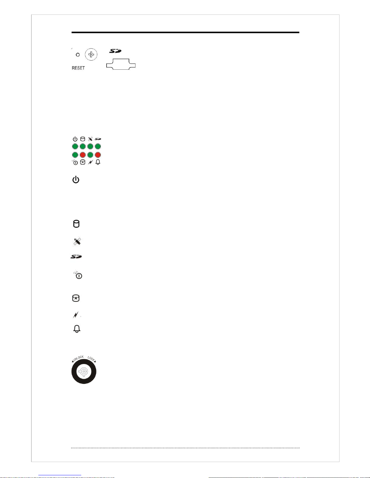
Reset/SD Card Slot
• Reset: Back to factory setup value of DVR. To reset system, Press hold reset button with sharp
pin and power on. Hold reset button until booting process is over.
• SD Card Slot : SD Card is available as storage. If no HDD valid, system records data on SD
card.
LED Display
display DVR power and working status
: LED doesn’t flicker even temperature goes down during operation. Internal Heater working
when system turns on the temperatures below -20℃ and LED is on after heating up system.
When power goes out, system displays ‘shut down’ message and system goes off after
discharging internal capacitor.
: HDD access status
: GPS signal received and position fix status
: Lights on when use SD Card as recording device
: Shutdown delay status. Performs this process by system setup time when ACC power is
off but Main is on.
: LED is on when there is no available HDD, SD Card
: Network access status
: Alarm Status.
Lock Key Switch
Use this key lock when add or remove HDD on HDD rack. To remove HDD during
system is working, unlock it and check system shutdown message first and then
remove HDD rack.
15
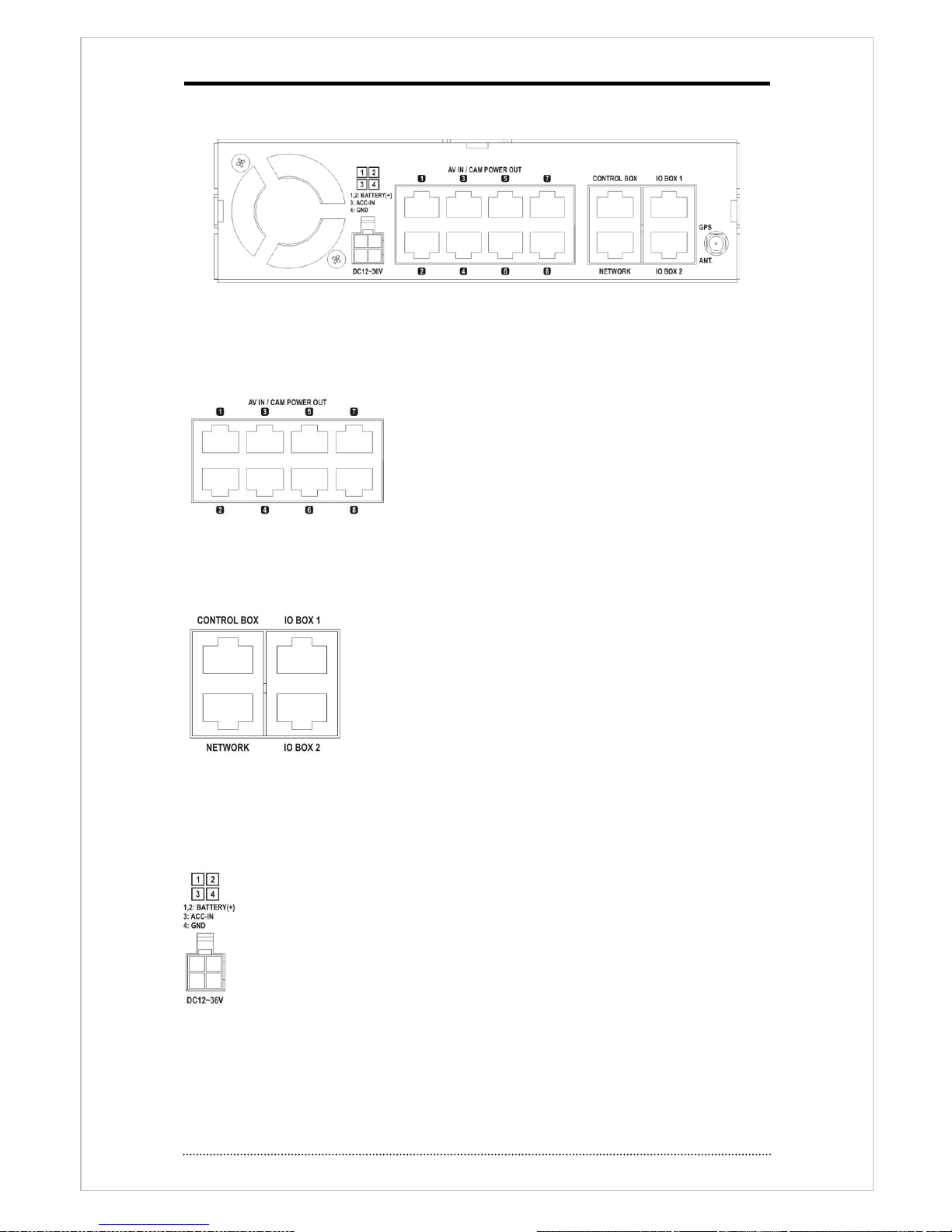
2-3-2 Rear panel
Note
: To connect cables on rear panel, the cover should be removed first and pass cables
through the hole on cover.
Video/Audio Input, Camera power supply
Use ‘audio/video’ accessary cable and connect 8 cameras
with camera power supply.
IO Box/Control Box/Network
Network port : Use UTP cable and connect to network and do remote view, playback & setup.
For more details, see ‘
chapture3-2. DVR Setup’.
Connect to wireless network with using 3G (GPRS) router on
network port. For more details about 3G router, ask Network service
provider or router manual which provided by manufacture
Control Box port : Use UTP Cable and connect to Control box.
When Control box is connected, the IR port on Control Box will be
used. The other IR port(on main unit) will be disabled.
IO Box 1/2 port : Connect IO box with UTP Cable. IO Box extend features such as
Sensor/Alarm, RS232, RS485.
Power input
This DVR can be operated with 12V and 24V power supplied vehicle. Connect pin 1,2
on (+) of battery. Pin 3 to (ACC) (+). Pin 4 as ground.
16
Others
GPS Antenna: Built in GPS is working on this DVR. SMA type GPS antenna
recommended to receive GPS data better.
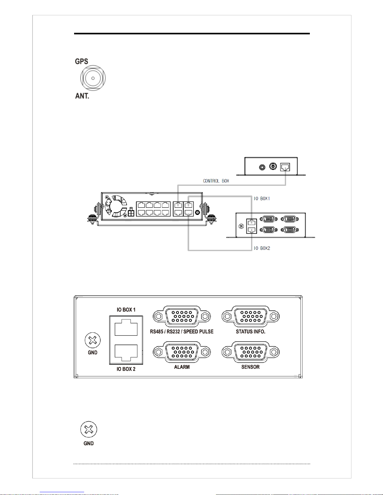
2-3-3 Main Unit IO Box/Control Box connection
-Use RJ45 cable to connect each units.(Main unit to IO and Control box.)
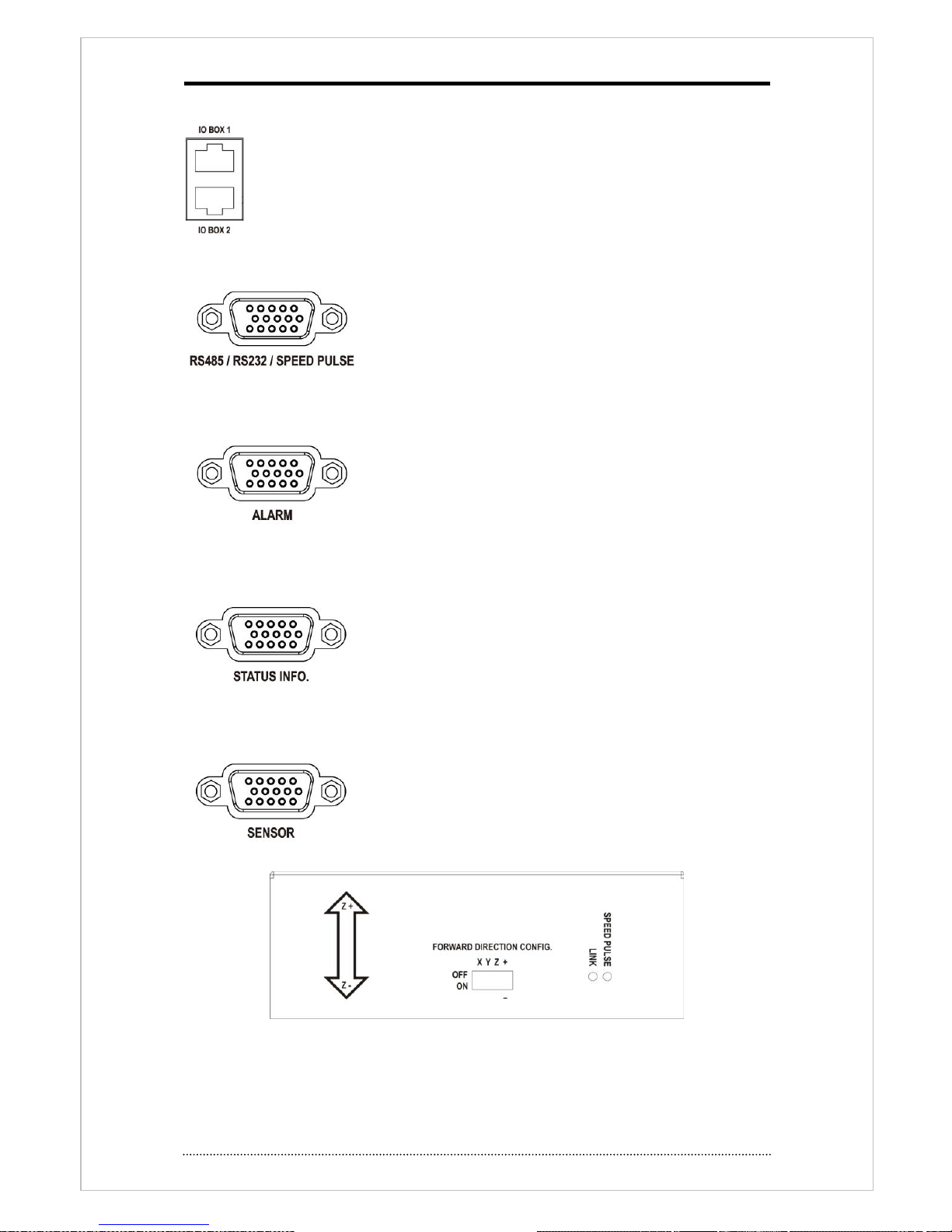
2-3-4 IO BOX
-Following picture shows front & rear side of IO BOX.
<rear side>
Case Ground
Use this port for ground connection to vehicle body.
17
Power and communication port
Use UTP Cable to connect to main unit.
RS485/RS232/SPEED PULSE input port
Connect speed pulse of the vehicle. Use provided accessory cable.
this also can be used when connect RS-485/232 communication.
Alarm Output
Connect alarm output to external devices. Addition power supply
required because this alarm is ‘Open-collector’ type.
Vehicle Status input port
Connect Vehicle Status with provide accessory cable.
Sensor Input port
Connect to external devices with accessory cable. Event signal
can be sent to DVR.
<Front>
18
<Top>
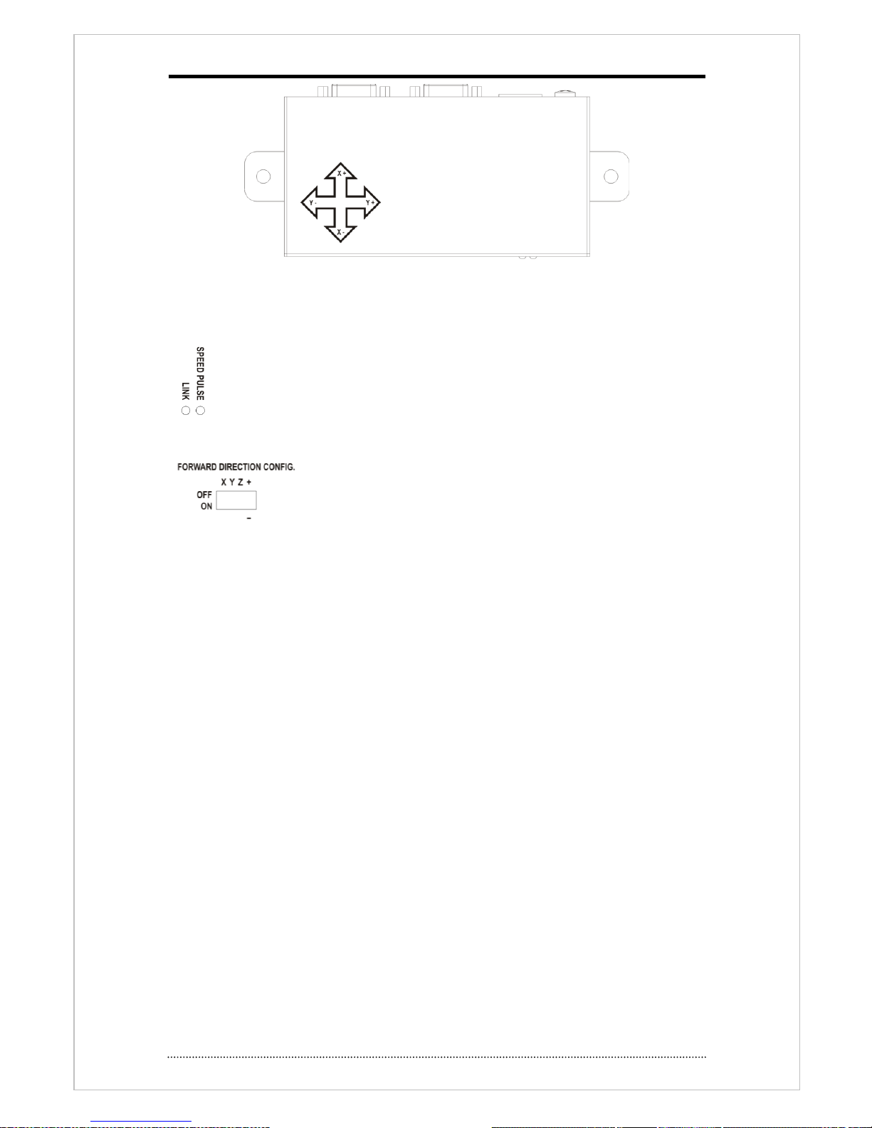
LED Display
Link : shows power on/off status of IO Box.
SPEED PULSE: Flickering by the pulse signal.
DIP Switch
Set moving direction and X,Y,Z axis and used as G-Sensor output
calibration.
19
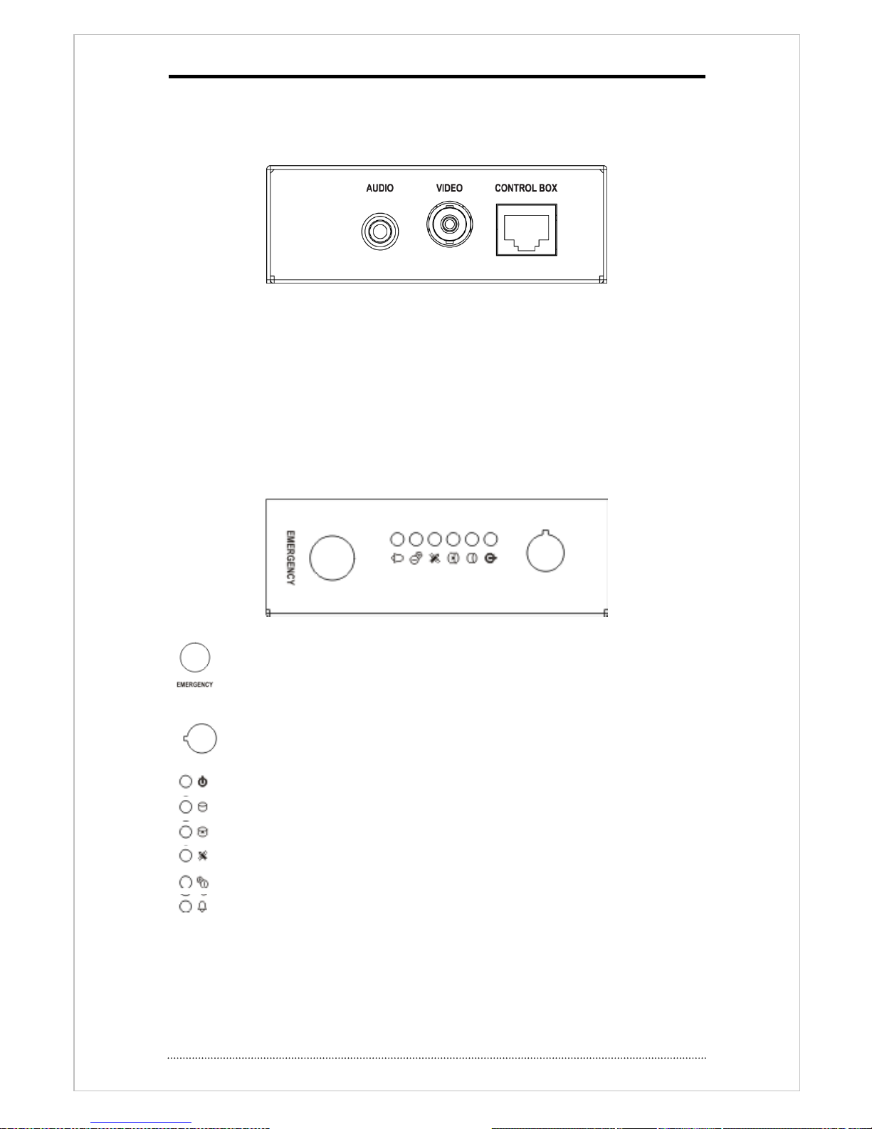
2-3-5 CONTROL BOX
Following picture shows Front & rear of CONTROL BOX.
<Rear>
AUDIO(Audio output)
Audio line out port. This works same as front panel’s audio port.
VIDEO(Video output)
This works same s front panel’s CVBS output port.
CONTROL BOX(Connection port)
Connect to main unit with using UTP Cable.
<Front>
EMERGENCY : DVR operates as emergency mode once this entered. Same as
‘PANIC’ button on remote controller.
IR receiving port for Remote controller : receive IR signal of remote controller.
: Lights on when power on status of Control Box.
: Lights on when HDD, SD Card is available.
: Lights on when HDD, SD Card is not available.
: Lights on GPS position fix after receiving data.
: Lights on when Shutdown delay process is working
: Lights on when alarm output is working.

20
3. Cautions
• Please connect the power cord only to the correct type of AC outlet indicated in the manual or
product specification. If connected to other types, fire and/or electric shock may result.
•Do NOT expose the product to moisture and humidity. Doing so may result in fire and/or
electric shock.
•Do NOT make too many power connections at the same power outlet. Fire and/or electronic
shock may result.
•Install the product at least 8 inches (20 cm) distance from other machines or electronic
products.
•Do NOT place containers with liquid on top of the product or close to the product. It may lead
to fire and/or electric shock as a result.
•Do NOT remove the case of the product or modify the product in any way. Doing so may result
in electric shock. If internal examination and maintenance are deemed necessary, contact the
authorized system vendors or technicians.
•Please use only the power cord provided with the product. Use of other types may result in fire
and/or electric shock.
•In case of smoke, smell or noise, promptly turn off the power switch and remove the power
cord from the product. Continued operation of the product may lead to malfunction or
damage of the product that cannot be repaired. Please request a customer service contact
from the authorized system vendors or technicians.
•Do NOT touch the product with wet hands. Doing so may result in electric shock.
•In case of lightning, immediately turn off the power and remove the power cord from the
product. Fire and/or electronic shock may result if these actions are not performed.
•If the product is dropped or damaged, turn off the power and remove the power cord form the
product. Continued operation of the product may result in malfunction or damage of the
product cannot be repaired. Please request a customer service from the authorized system
vendors or technicians.
•Do NOT score, bend, twist, pull or heat the power cord. Damage to the power cord may result
in fire and/or electric shock.
•Do NOT operate or store the product in areas of extreme heat or cold, high humidity, in front
of an air conditioner, or where there is excessive dust. It may result in malfunction of or
damage to the product.

21
Chapter 3. Using DVR
1. Basic Operation
1-1. Remote controller use
This DVR can be controlled by USB port(front) or Remote controller.
Button
Description
USB Port
Two USB ports are located on front panel.
Numeric button (0~9)
Press number button and ‘Enter’ button make displays
selected camera to display full screen. Buttons are used to
enter passwords.
MENU / EXIT Button
Enters the Setup Menu. User will need to enter the authorized
password to assess Setup. In Playback mode, MENU button
displays the Playback Menu.
DISPLAY Button
Changes the screen display mode in the current screen or
playback screen.
SEQUENCE Button
Display live channels sequentially.
Up, Down, Left, Right
Arrow, ENTER Buttons
Change settings for the product in MENU mode or used in PTZ
control mode. (pan, tilt)
BACKUP Button
Backup recorded data to an external storage device.
PLAYBACK Button
Switch to playback mode from live mode.
PAUSE Button
Pause playback image on playback mode.
- Display menu to save PTZ preset on PTZ mode.
PLAY Button
Play video forward. Press button repeatedly to increase play
speed up to max 32 times (1, 2, 4, 8, 16, 32 times) faster. Use
this button to move right when setting the menu.
- Focus on far distance in PTZ mode.
R.PLAY Button
Plays the video backward. Press the button again to increase
playback speed up to max 32 times (1, 2, 4, 8, 16, 32 times)
faster. Use this button to move right when set the menu.
- Zoom out on PTZ mode.
STEP FORWARD Button
Move forward frame by frame on paused status. Use this
button to move up when set menu.
- Focus on near distance in PTZ mode.
STEP BACKWARD Button
Move backward frame by frame on pause status. Use this
button to move down when setting the menu.
- Zoom In in PTZ mode.
EJECT Button
It will open or close the backup drive such as CD-RW or DVD
- Display menu to load PTZ presets in PTZ mode.
PTZ Button
Changes to PTZ control mode from live mode.
ZOOM button
Use this on live display mode.

22
ZOOM Button
Zoom current camera image on screen.
PIP Button
Change to PIP screen mode from live screen.
FREEZE Button
Freeze current screen.
AUDIO Button
Select channel for live & playback audio output.
OSD Button
Turn on/off OSD display.
LOG Button
Check system log information.
E.REC button,
Control Box Emergency
button
Press E.REC button to apply Emergency Recording Mode for
whole channels. It displays "!" on the screen. To stop E.REC
mode, press button again.
Front Status LED
Power, HDD, Network, Alarm, Record Bad, Shutdown delay,
SD, GPS
Control Box Status LED
Power, Recordable, Alarm
Record Bad, Shutdown delay, GPS, Emergency
Lock Key
Open front cover of HDD rack with provided key. To remove
HDD during system operation, Open front cover and wait until
system shut down safely and then remote HDD rack.
23
1-2. Turning on the System
Once DVR is installed properly on vehicle, power is on when user turn the vehicle on. It takes
20-30sec. in initializing
Heating sensor activates when temperature is below -0°C (32°F) until it reaches HDD working
temperature. If SD card installed, system records on SD card first until HDD reaches on
working temperature and it switches recording to HDD automatically.
Recording stops when you turn off engine. This mobile dvr only working during the engine is
on.
Notice
: Removable HDD can be connected on your PC HDD after you remove from HDD rack. To
remove HDD from its rack, turn off system safely first and remove. Even system is operating
you can remove HDD after remove front cover. Once front cover removed, system will shut
down automatically and then you can remove HDD.
Note
: HDD should be formatted when it is installed first time.
“MENU > RECORD > Storage > HDD format”
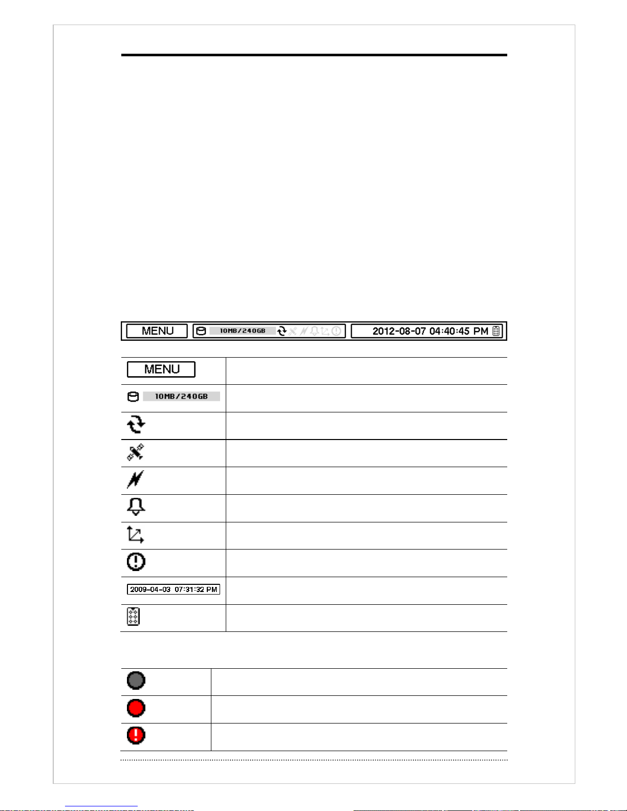
1-3. Status Bar
Menu bar will appear bottom of screen as follows.
Press Menu to open main menu list.
Show used space as % of HDD being used.
Turned on when the HDD is set as overwritten.
Turned on when GPS data receiving
Turned on when the system is connected to network.
Turned on when Alarm is on active.
Turned on when when G-Sensor is on active
Emergency Recording mode.
Display Time & Date information
Turned on when IR remote controller is on active
1-4. OSD Icons
No Recording
Recording (Red)
E.REC (Emergency Recording)
24
Event Recording (Red)
Pre Event Recording (Blue)
Motion Detection
Sensor Detection
Text In
PTZ Camera
Instant Backup
Clip Maker (Blue)
Backup (Red)
Video Loss
1-5. User or Admin Login
Press MENU to enter main menu. Login screen appears to enter ID and Password. Up to 8
numbers are required on password with combination of numbers from 0 to 9. Click numeric
buttons on the bottom to enter password. Click “…” button to pop up virtual keyboard when using
front buttons or remote controller to enter password.
The factory default password is ‘none’, press OK to log in system for the first time log in.
Password can be set in password setup option (MENU > SYSTEM > User). System will be
automatically log out if it is not in-use for a while. This "Auto Logout Time" can be set in
password set up option (MENU > SYSTEM > User).
1-6. Main Menu
The Main Menu of DVR consists of SYSTEM, DEVICE, DISPLAY, RECORD, NETWORK and EVENT.
And each menu consists of various sub menus that allow detail set up of the system. Use Mouse,
Remote Controller or Front Buttons to access each menu.
Note
: Please make sure system log out when setup or operation is completed to prevent any
unauthorized changes of system setup or operations.
Main Menu
System
Information

25
Date & Time
User
Quick Setup
System Log
Device
Camera
Audio
Alarm
Keyboard
RS232 & RS485
Vehicle
Display
Display
VGA
Composite
Digital Signage
Record
Storage
Record
Utilities
Network
Address
DDNS
Notification
Transmission
Event
Sensor
Motion
Video Loss
Text-In
System
G-Sensor
LOGOUT
SHUTDOWN
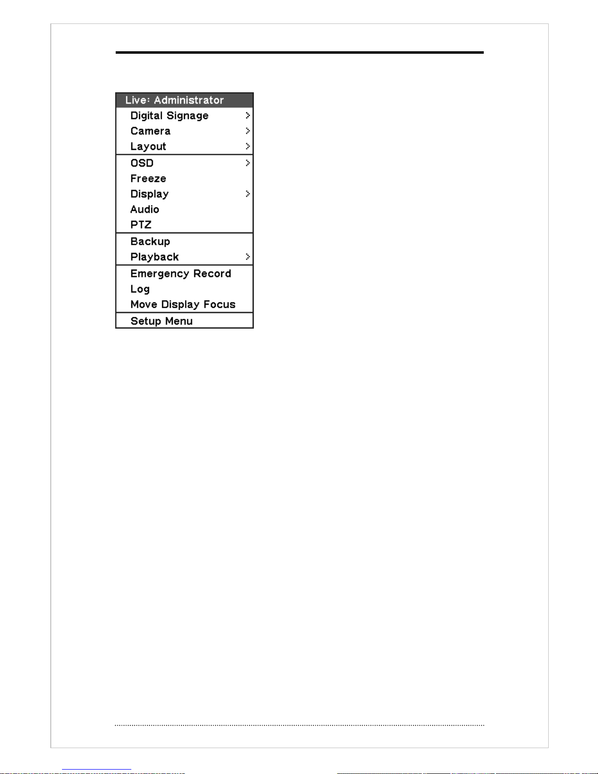
26
1-7. Popup Menu
Additional Contextual Menu screen appears by pressing right button on the Mouse.
Digital Signage: display digital signage through VGA or CVBS port.
Camera : Select camera number
Layout : select screen division (only available on 8/16 channel DVR)
OSD: OSD Display option
Text in information : select display option when system has POS / ATM connection.
Screen pause: Pause live screen
Display : display menu option
Display > Sequence : Select sequence display
Display > zoom: screen zoom (x2, x4, x8)
Display > PIP: Select PIP mode in single channel mode.
Audio : Select Audio output
PTZ : Select PTZ options
Backup : Select backup options
Playback : Playback recorded data
E. Record : Start Emergency Recording
Log : Select System/Event log
Move display focus : Switch main control display, such as setup, between VGA and Composite
output.
Setup Menu: return to main setup menu.
For more detail information about popup menu, see ‘Chapter3. DVR operation 2.DVR setup’. 2.
DVR Setup
27
2. DVR Setup
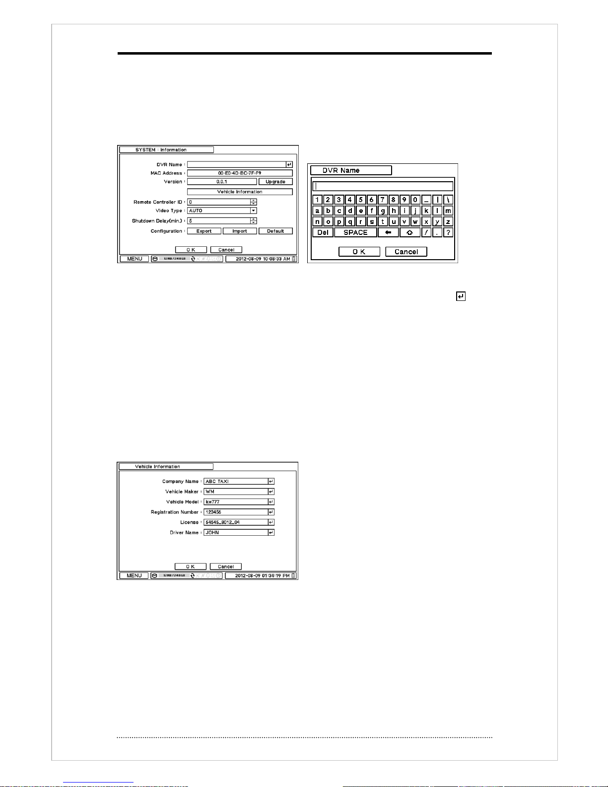
2-1. System
In SYSTEM menu, System configuration options for general Information, Date &Time, User, Quick
Setup and System Log can be selected.
2-1-1. MENU > SYSTEM > Information
In Information screen, DVR Name, MAC Address, Version, Upgrade, Mac Address, Remote
Controller ID and Configuration options can be selected. Select and press DVR Name or to
change DVR name. Use virtual keyboard to enter DVR name.
To upgrade system, place upgrade file on USB Flash Memory and put it on DVR. Once device is
recognized, press upgrade button to execute system upgrade.
Upgrade will take approximately 5 minutes. DVR will reboot automatically when the upgrade is
completed.
Note
: DO NOT remove USB Flash Memory or turn off the system during the upgrade. Removing
USB Flash Memory or Turning off the system during the upgrade may cause system
malfunctioning.
Vehicle Information
Enter following information.
Company, Manufacture, Model, Registration
number, License number and Driver.
Remote Control ID
Enter Remote Control ID to control multiple DVRs individually. If Remote Control ID remains as 0,
no need to select Remote ID when using remote controller. It will work as general ID for any
remote controls and a remote control will communicate with any DVRs with ID 0.
Camera Signal type
This DVR detect incoming signal automatically(NTSC/PAL) and select it manually.
Holding shutdown(min)
Hold power on system after turn off engine. DVR system record data during configured time and
28
turn off by itself. Set time from 5 to 60minute.
Configuration
System settings can be saved and loaded using Configuration option
Export: Save settings to USB Flash Memory
Import: Load saved settings from USB Flash Memory
Default: Load factory default settings
Note
: Configuration Import does not affect or change system and network settings.
Net Network settings changed when select Default option.
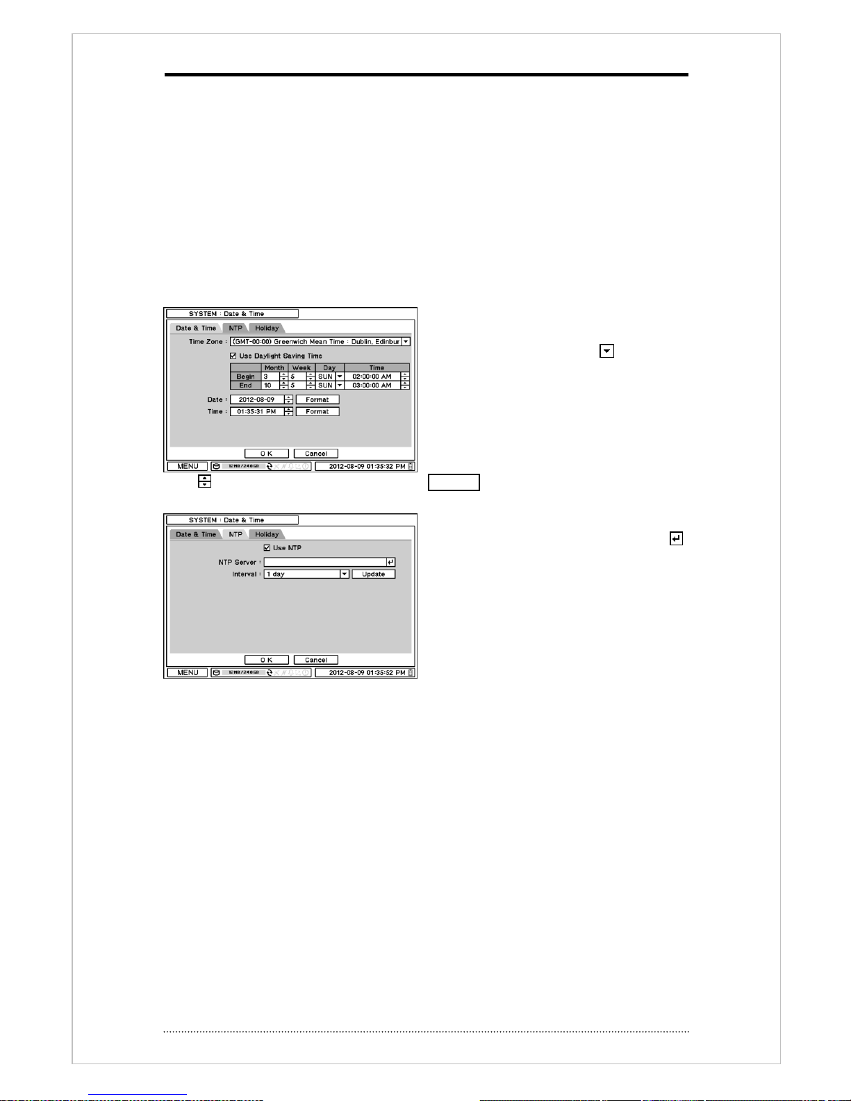
2-1-2. MENU > SYSTEM > Date & Time
In the Date & Time, Time Zone, Date, Time,
NTP Server, Holiday options can be selected.
Highlight and press Time Zone to select
right Time Zone.
Select ‘Use Daylight Saving Time’ if it is
applicable. Enter start and end date/time for
local ‘Daylight Saving Time’.
Press button to set up Date and Time. Press Format button to select a date & time display
format.
Select ‘Use NTP’ to enter Time Servers to be
synchronized with DVR. Highlight and press
to enter Time Server using the virtual keyboard.
Press ‘Update’ to synchronize the DVR time
with the registered time server.
Note
: NTP is not essential for DVR operation.
Any type of Standard Time Server can be used
(e.g. time.windows.com). Time Synch might
not be completed due to heavy traffic or delays from the Time Synch server.
29
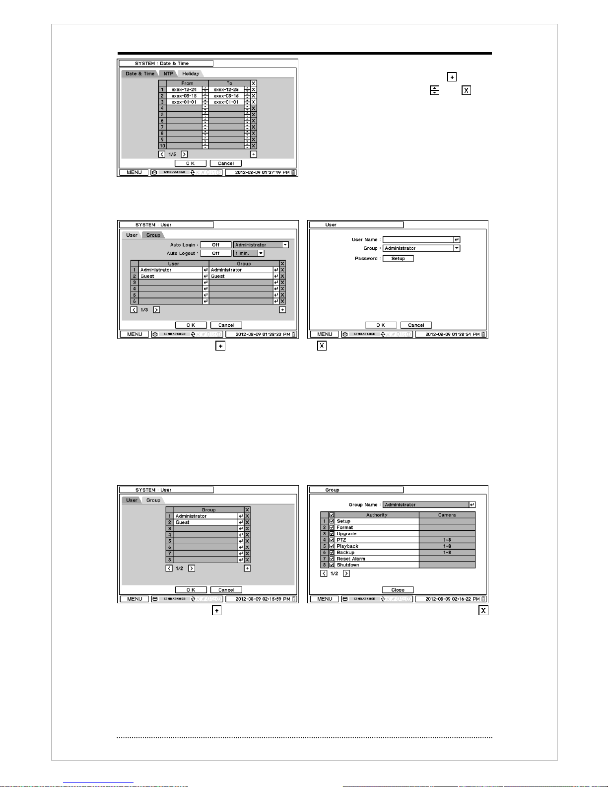
Press Holiday to set specific date as Holiday
setup. Set specific date by pressing button.
Change and delete dates using and
buttons.
Note
: Holiday may not same date every year.
User have to update every year.
2-1-3. MENU > SYSTEM > User
User can define new user and group permissions on this page.
Add new user with press button. To delete, use button.
Auto Login: It allows user to log in right after system boots up automatically. As a system allows
auto log in without the authentication process please make sure DVR has a limited access by
non-authorized personnel
Auto Logout: Set On or Off Auto Logout option.
User name : Enter user name
Group : Select a group which a new user will belong to
Password : set a new password or change a password.
Note
: No password defined on initial starts.
Register new group use button and set permission of group to each user. To delete, press
button.
 Loading...