

Page 1
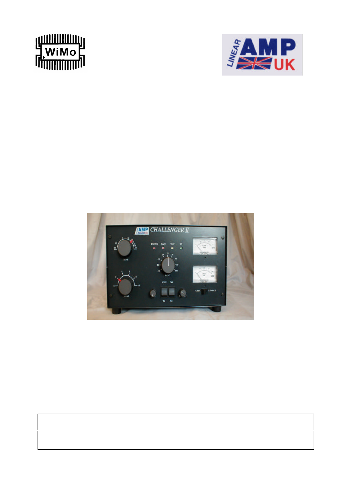
CHALLENGER II
HF LINEAR AMPLIFIER
(GS 35 Model)
Operating Manual
WiMo Antennen und Elektronik GmbH
Am Gäxwald 14, D-76863 Herxheim Tel. (07276) 96680 FAX 6978
http://www.wimo.com e-mail: info@wimo.com
Page 2

INDEX
1. Specifications
2. Introduction
3. Installation
4. Operating controls
5. Operation
6. Circuit diagrams
CAUTION
There are dangerously high voltages inside the amplifier when the power is
switched on. DO NOT remove the covers unless the power has been
disconnected and sufficient time has elapsed for the capacitors to discharge.
NOTE
The Challenger is capable of a greater power output than the CW rating shown in the
specifications. In order to achieve the stated PEP output, the amplifier must be
capable of operating CW at the same level for short periods. Do not try to operate the
amplifier at greater than the recommended level.
If the amplifier is operated for long periods at levels greater than the recommended
ones, then damage may occur. Care should be taken not to exceed 400mA grid current
or to drive with more than 130W continuous wave drive. Also care should be taken
not to exceed 1.5 : 1 SWR.
WiMo Antennen und Elektronik GmbH
Am Gäxwald 14, D-76863 Herxheim Tel. (07276) 96680 FAX 6978
http://www.wimo.com e-mail: info@wimo.com
Page 3

(1)
1. SPECIFICATIONS
Function…………….The Challenger is a desk top linear RF amplifier with a nominal
output of 1500W covering the HF Amateur bands.
Type of Emission…………..…………………………………………SSB/CW/RTTY
Output power…………………………1500W SSB or CW, 1000W continuous RTTY
Gain……………………………………………………………………...13dB nominal
Power requirements………………………………..…..230VAC at 20Amps, 50/60Hz
Duty cycle………………………………………Full O/P with normal amateur service
Cooling………………………………………………………………Forced air cooling
Frequency coverage………………..All amateur bands 1.8 - 29.7 MHz (incl. WARC)
Input impedence……………………………………………..50 ohms, VSWR < 1.5 : 1
Valves…………………………………………………….Single GS 35 ceramic triode
Harmonics………………………………………………………………..-50dB typical
Intermodulation…………………………………………more than -35dB at 1kW O/P
DC Voltage………………………………………………………………….3600 VDC
Metering………………..…….Plate current, switchable Grid current / RF relative O/P
ALC……………………………………………………….Front panel adjustable ALC
Protection……………………………….Primary AC fuses, grid current trip, soft start
and timer at switch-on
Dimensions…………………………………….….16in wide x 9.5in high x 17in deep
410mm x 240mm x 475mm
Weight……………………………………………………………………………..29kg
Page 4

(2)
2. INTRODUCTION
The Challenger is a high quality RF linear amplifier which is designed around a single
GS 35 medium mu triode in grounded grid configuration. The amplifier uses a Pi
network in the output circuit and a tuned input circuit on each band to give maximum
rejection of harmonics. The amplifier is fan-cooled with an internal flatpack blower to
provide forced air cooling for the valve and also good circulation around the
transformer.
The GS 35 valve must be allowed to warm up properly hence a 2.5 min start-up
timing circuit is incorporated which disables the PTT operation until the time has
elapsed. There is also a soft-start circuit to prevent a high EHT surge on switch-on.
There are five LED status indicators READY, WAIT, GRID, TRIP and ON-AIR.
Two panel meters provide continuous indication of Plate current and a switch-selected
choice of Grid current or relative RF output. The latter should normally reside in the
Grid current position as it is most important to monitor the grid current at all times.
A nine position switch, one for each band 10, 12, 15, 17, 20, 30, 40, 80 and 160m,
selects band coverage.
The Tune and Load controls are attached to the capacitor using 6:1 epicyclic drives to
ensure silk-smooth tuning.
The power supply uses a specially designed 2.5kVA toroidal transformer, which
provides the three separate voltages needed in the amplifier:-
1. HIGH VOLTAGE which is 3600V (voltage doubled from the transformer),
the main voltage applied to the valve anode.
2. HEATER SUPPLY which is 13V at 4Amps.
3. CONTROL VOLTAGE which is 12V used for pulling in the Tx/Rx relays and
gives the LEDs the control condition of the amplifier.
The cabinet chassis is made from Zintec steel plate for maximum strength but the
covers and front panel are aluminium to reduce weight.
Page 5

(3)
3. INSTALLATION
SETTING UP
a) Unpack the amplifier and check that it is undamaged. The carton should also
contain an operating manual, phono plugs (for relay switching lead) and spare fuse.
Please retain the packing and box should it be necessary to ship it or move it to
another location.
b) Ensure you have a reasonable airflow around the site you have chosen to install
your amplifier. Do not enclose the cabinet or restrict the airflow in any way. Try to
avoid extremes of heat, humidity or dust in order to give many hours of trouble-free
operation.
c) Ensure ALL connectors to be used by yourself are of a sufficient electrical
standard to carry the higher RF output generated by the amplifier. To properly tune
the amplifier a high quality Wattmeter (e.g. Bird thruline) should be used to measure
the output and if possible a similar meter between the driver and the amplifier to
correctly measure the input.
d) NEVER attempt to operate the amplifier without first connecting an antenna or
50ohm dummy load. Check the SWR of the antenna with the amplifier in the OFF or
STBY position and do not operate the amplifier if the SWR is greater than 2 : 1.
e) Check that the front panel switches are in the STBY and OFF positions.
CONNECTIONS
a) POWER CABLE. The amplifier is fitted with a 3-wire Mains cable terminated in
a 13A plug (UK only). The supply must be 230VAC single phase, 50/60 Hz.
b) OUTPUT COAX. Any good quality 50 ohm coax capable of carrying up to
2000W at 28MHz is suitable. This needs an SO239 connector to go on to the
amplifier and whatever connector is required for your Wattmeter.
c) INPUT COAX. Good quality 50 ohm coax with an SO239 connector to the
amplifier and a connector of your choice for the driver.
d) RELAY SWITCHING LEAD. Two phono plugs are provided for you to make a
lead to go into the PTT and ALC sockets on the rear of the amplifier and connect
to the linear amplifier connections on your transceiver.
Page 6

(4)
4. OPERATING CONTROLS
FRONT PANEL CONTROLS
1. ON/OFF SWITCH………………………………………Mains power on and off
2. STBY/TX……………………………………………..Amplifier standby / operate
3. PLATE METER…………….….1.5 Amps, monitors the plate current of the valve
4. GRID METER……………………………....0 - 400mA, monitors the grid current
which should not rise above 400.
or RF OUT METER……………………..….relative RF O/P adjustable with RF SET
5. GRID / R.F. OUT…………...Switches Grid meter to use as relative RF O/P meter
6. RF SET …………………………………When the above switch is at RF Out, this
control adjusts the sensitivity of the meter
7. ALC …………………………When turned anti-clockwise until it clicks, the ALC
is off and the amplifier power is determined by the
transceiver power control (which should not
exceed 130W). Click and turn clockwise to set
required output, this will adjust the drive power
from your transceiver automatically.
8. BAND SWITCH………………………..…….Selects the desired frequency range
9. TUNE CONTROL……………………..Controls the amplifier resonant frequency
10. LOAD CONTROL………….………………Controls the amplifier output loading
(For approximate Tune and Load positions, see back page of this manual)
Page 7

(5)
11. POWER LED……………………………… Indicates power is on (2-3sec delay)
12. WAIT LED…………………………...………..PTT operation is disabled while lit
13. TRIP LED………….…..Shows amplifier is disabled due to excessive grid current
14. ON-AIR LED………………………………..……….Shows the amplifier is on-air
Notes on LED indicators:
a) The WAIT LED comes on when the amplifier is switched on and indicates that
the timer is in operation. The amplifier cannot be operated at this time. After
approx. 2.5 minutes the light will go out .
b) The TRIP LED comes on when the grid current has exceeded 400mA, due either
to excessive drive being applied or to mis-tuning. In either case, the amplifier
ceases to operate until the cause has been rectified and the amplifier re-set. To
reset the amplifier, make sure the Tune and Load controls are in the correct
positions and the drive turned down a little. Now press the STBY/TX switch to
STBY and immediately back to TX, the Trip LED should now have gone out and
the amplifier is able to be keyed once more.
REAR PANEL
1. FUSE HOLDER………………………………………1.25" (30mm) 15 Amp fuse
2. MAINS……………………………………………….……Mains cable, 230 VAC
3. TX…………………….SO239 connector, coaxial INPUT to amplifier from driver
4. ANT…………………...SO239 connector, coaxial OUTPUT to antenna through a
suitable power meter
5. PTT………………………………….……….Phono connector to transceiver relay
6. ALC………………………………………….Phono connector to transceiver ALC
NB. Refer to transceiver operating manual for connections to a linear amplifier.
7. EARTH……………………………………May be connected to a suitable ground
Page 8

(6)
5. OPERATION
SET-UP
Connect all the cables as previously described in the manual, then double check.
Ensure that your transceiver is set for operation with a linear amplifier (refer to your
transceiver manual). When you are satisfied that everything is correct and the
STBY/TX switch is on STBY, switch the amplifier ON. The green LED should be lit
(3-4 second delay for soft-start to operate). After approx. 2.5 minutes the red WAIT
LED will go out indicating that the valve has warmed up and is ready for operation.
Select the band you wish to operate on and set the Tune and Load controls to the
settings shown on the back page of this manual. Now put the STBY switch to TX,
which puts it into the operate mode.
With no RF drive applied, key the amplifier and check that the plate meter shows a
standing current of about 100mA. The green ON-AIR LED will be on when the
amplifier is keyed.
TUNE-UP
Now set your transceiver to 50 Watts output, in either CW or FSK, key the amplifier
and using the Tune control adjust for maximum output on the desired frequency. The
Load control setting as per the chart is an optimum position for the amplifier running
1300W into a 50 ohm load. If a power of less than 1kW is required, the Load control
can be adjusted clockwise to a setting where the efficiency becomes greater but
ensure the grid current remains low. Running at 1300W the drive control on your
transceiver should be around 90W and the positions on the Tune and Load chart
should be correct.
The amplifier is now ready for operation.
OPERATION
The mode of operation, CW or SSB, can now be selected and operate as normal.
When the amplifier is in the STBY position the RF goes straight through from the
transceiver to the antenna, and when it is in the TX position the amplifier comes into
operation.
During operation, keep a careful eye on the Grid meter making sure it does not go too
high. (However, if 400mA is exceeded then the Grid Trip will operate)
Page 9

(7)
OPERATING PRECAUTIONS
To ensure safe and reliable operation please regard the following precautions:-
HIGH VOLTAGES CAN BE LETHAL. Never try to operate your amplifier with the
covers removed. If it is necessary to work inside the cabinet, always disconnect the
Mains supply and allow the capacitors to discharge fully.
Never operate the amplifier into a load or antenna with an SWR greater than 2 : 1.
Always tune the amplifier for resonance using low drive at the operating frequency.
The components in the amplifier are designed to be used within the parameters of the
specifications on page 2. Excessive drive giving output in excess of these specifications will shorten valve life and could affect the reliability of other components.
Page 10

(8)
WARRANTY
Linear Amp UK Ltd warrants to the original purchaser that this product shall be free
from defects in material or workmanship for 12 months from the date of the original
purchase. Valves are excluded from this warranty.
Notification should be given as soon as possible after discovering a possible defect.
Carriage charges for any parts or units submitted for replacement or repair under this
warranty must be paid by the purchaser.
Correct maintenance, repair and use are important to ensure proper performance from
this product. Carefully read the operating manual. This warranty does not apply to any
defect Linear Amp UK Ltd determines is caused by (1) improper maintenance or
repair, including the installation of parts or accessories tat do not conform to the
quality and specification of the original parts; (2) misuse, abuse, neglect or improper
installation; (3) accidental or intentional damage; (4) acts of God.
Linear Amp UK Ltd is not responsible for damage to other equipment or property or
any other consequential or incidental damage of any kind.
This warranty is not transferable from the original owner on sale of the unit to
another.
WiMo Antennen und Elektronik GmbH
Am Gäxwald 14, D-76863 Herxheim Tel. (07276) 96680 FAX 6978
http://www.wimo.com e-mail: info@wimo.com
 Loading...