

Page 1
Operating Instructions
& Service Parts Manual
# 28910
SHR™
Record purchase information for quick reference:
WILTON
427 New Sanford Road
LaVergne, Tennessee 37086
Ph.: 800-373-8206
www.wiltontools.com
Strut and
Threaded Rod
Shear
Document No. M-28910
Edition 1
10/2020
Copyright © 2020 WILTON
Page 2

1.0
IMPORTANT SAFETY INSTRUCTIONS
WARNING – To reduce risk of injury:
1. Read and understand all warnings posted
on the machine and in this manual. Failure
to comply with all of these warnings may
cause serious injury.
2. Do not use this shearing machine for other
than its intended use.
3. Replace warning labels if they become
obscured or removed.
™
4. Make sure the Wilton SHR
supported by the guide bars and bases, so
that it will not tip over during use.
5. Keep ground or floor around the machine
uncluttered and free of scrap material, oil
and grease. Wear non-slip footwear.
6. Always wear protective eye wear when
operating machinery. Eye wear shall be
impact resistant, protective safety glasses
with side shields which comply with ANSI
Z87.1 specifications. Use of eye wear
which does not comply with ANSI Z87.1
specifications could result in severe injury
from breakage of eye protection.
7. Wear gloves when handling steel work
pieces to prevent possible injury from sharp
edges.
8. Wear hearing protection if noise becomes
uncomfortable or reaches unsafe levels.
9. Crushing hazard - Keep hands away from
cutting area during operation.
10. Always inspect the SHR
Check for misalignment of moving parts,
binding of moving parts, breakage of parts,
mounting and any other conditions that
may affect the machine’s operation. If
is properly
™
before use.
damage is found, repair the machine
immediately or replace it.
11. Disconnect from power/hydraulic source
before performing any maintenance or
cleaning.
12. Have machine serviced only by qualified
personnel, using authorized replacement
parts.
13. Provide for adequate space surrounding
work area and sufficient lighting.
14. Do not use this machine while tired or under
the influence of drugs, alcohol or
medication.
15. Keep bystanders, especially children, away
from the area while using the machine.
16. Give your work undivided attention.
Looking around, carrying on a conversation
and “horse-play” are careless acts that can
result in serious injury.
17. Maintain a balanced stance at all times. Do
not overreach while performing the work.
WARNING: This product can expose
you to chemicals including lead which is
known to the State of California to cause
cancer and reproductive harm. For more
information go to http://www. p65warnings.
ca.gov.
2 WSHR-3017 Strut & Threaded Rod Shear
Page 3

WARNING: Some dust, fumes and gases created by power sanding, sawing, grinding,
drilling, welding and other construction activities contain chemicals known to the State of
California to cause cancer and birth defects or other reproductive harm. Some examples of these
chemicals are:
lead from lead based paint
crystalline silica from bricks, cement and other masonry products
arsenic and chromium from chemically treated lumber
Your risk of exposure varies, depending on how often you do this type of work. To reduce your
exposure to these chemicals, work in a well-ventilated area and work with approved safety
equipment, such as dust masks that are specifically designed to filter out microscopic particles.
For more information go to http://www.p65warnings.ca.gov/ and http:// www.p65warnings.ca.
gov/wood.
Familiarize yourself with the following safety notices used in this manual:
This means that if precautions are not heeded, it may result in serious, or
even fatal, injury.
This means that if precautions are not heeded, it may result in minor injury
and/or possible machine damage.
2.0 About this machine
The SHR™ Strut and Threaded Rod Shear is a portable hydraulic machine designed to quickly cut
common U.S. manufactured brand struts in 12, 14, 16 and 18-gauge mild steel. A single set of blades
will provide thousands of clean, even cuts, eliminating the need for deburring. Contact WILTON for
special application blade and hydraulic sets. This product has been designed and constructed to
provide consistent long-term operation, if used in accordance with instructions as set forth in this
document. NOTE: This machine is not designed for use with fiberglass, aluminum, or stainless steel
strut.
Register your product using the mail-in card provided, or register online:
http://www.wiltontools.com/us/en/service-and-support/warranty/registration/
3.0 About this manual
This manual covers operation and maintenance procedures for the SHR™ Strut and Threaded Rod
Shear. It contains instructions on setup, safety precautions, general operating procedures,
maintenance instructions and parts breakdown. If there are questions or comments, please contact
your local supplier or WILTON. WILTON can also be reached at our web site: www.wiltontools.com.
Retain this manual for future reference. If the machine transfers ownership, the manual should
accompany it.
WILTON 3
Page 4

4.0 Specifications
Table 1
Model number WSHR-3017
Stock number 28910
Power supply and cylinder
Required power supply (not provided) 10,000 PSI hydraulic
Recommended hydraulic fluid (not provided) ASTM 215, or equivalent
Cutting cycle 3 seconds
Cylinder linear force 30 short tons (27.2 metric tons)
Cylinder stroke 1 in. (25.4 mm)
Standard blade set capacities
Deep strut 1-5/8 x 1-5/8 in. (41.3 x 41.3 mm)
Shallow strut 1-5/8 x 13/16 in. (41.3 x 20.6 mm)
Maximum capacity for cut material 1 12 gauge mild steel
Maximum cut length when using stock stop &
included guide bars
2
Minimum strut length 7-5/8 in.
Threaded rod material 1 Low carbon steel (ASTM A307, grade A)
Threaded rod diameters 1/4, 3/8, 1/2, 5/8 in.
Main materials
Body frame ductile iron, ASTM A536 Grade 80-60-03
Blade set carbon tool steel, ASTM W5
Stock rest and back stop steel
Support and rods aluminum extrusion
Dimensions
Assembled dimensions (LxWxH) 26-1/8 x 17-1/32 x 10-3/8 in.(664 x 432 x 264 mm
Shipping dimensions (LxWxH) 26 x 13 x 10-5/32 in.(660 x 330 x 258 mm)
Weights
Net weight 71.5 lb. (32.5 kg)
Shipping weight 76 lb. (34.5 kg)
1
Not designed for use with fiberglass, aluminum or stainless steel.
2
For longer workpieces, install 1-in. diameter rods (not provided) to desired length.
L = length, W = width, H = height
The specifications in this manual were current at time of publication, but because of our policy of
continuous improvement, Wilton reserves the right to change specifications at any time and without
prior notice, without incurring obligations.
17 in.
4 WSHR-3017 Strut & Threaded Rod Shear
Page 5

setup or operation of the Strut Cutter. Failure to comply may cause serious injury.
Read and understand the entire contents of this manual before attempting
5.0 WSHR-3017 overview
Figure 1
6.0 Shipping contents
1 Main unit with hydraulic cylinder
1 Stock rest assembly
2 Bases
1 Stock stop
1 Blade set (pre-installed)
4 Lock knobs large
2 Lock knobs small
2 Guide bars w/scale 17-in.
1 Instructions and parts manual
1 Product registration card
Remove all contents from shipping carton, and check for shipping damage or missing parts. If either
of these is discovered, contact your dealer or Wilton at the phone number on the cover.
WILTON 5
Page 6
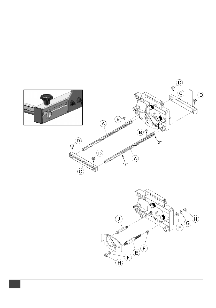
7.0 Assembly
See Figures 2 and 3.
1. Insert two guide bars (A) through the frame holes. The guide bars are identical; however, they
must be oriented as shown in Figure 2. Tighten the guide bars in place with the small lock knobs
(B).
2. Slide base (C) with stock stop attached onto the bars. Make end of bars flush with outer surface
of base to ensure proper scale use, see Figure 2 inset. Install large lock knobs (D) to secure.
3. Slide base (C) onto opposite end of bars as shown. It is not important that the bar be flush on
this end. Secure with knobs (D).
Figure 2
4. Thread the stock rest pivot rod (E) into
the frame, with flat washers (F), lock
washer (G) and nylon lock nut (H).
5. Thread the stock rest support rod (J)
into frame.
6. Install stock rest onto the rods and
secure with flat washer (F) and lock nut
(H).
7. The stock rest should be snug but still
able to rotate freely out of the way.
6 WSHR-3017 Strut & Threaded Rod Shear
Figure 3
Page 7
8.0 Operation
Guide bars and bases must
be used during operation to prevent unit
from tipping.
1. Connect 10,000-psi hydraulic power
source (not provided) to the universal
coupling on the cylinder. Use clean ASTM
215 or equivalent hydraulic fluid.
2. Turn on hydraulic power source and
observe the machine’s operation without
strut inserted. The blade set consists of a
stationary blade in front and a moving
shear blade in back. Watch shear blade
motion from rear of machine; it should
have smooth movement. When shear
blade has returned to rest position, both
blades should remain aligned.
3. Make sure locking knobs holding the
stationary blade are tight. Loose knobs
will cause additional load on the blades
and may shorten their life span.
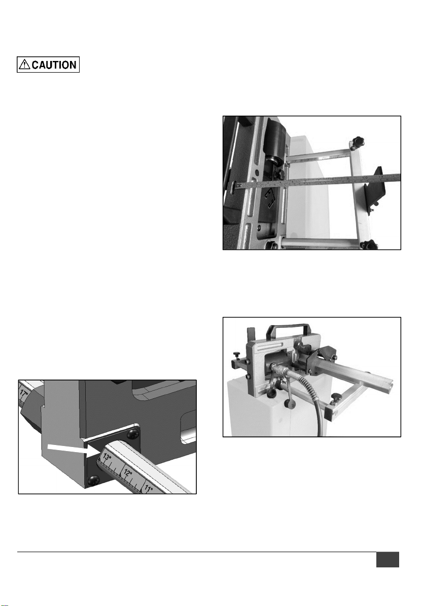
4. Adjust guide bars for stock stop position.
The scale indicates length from the cutting
blade to the stock stop. Measurement is
read at the angled edge of the red plate.
See Figure 4.
NOTE: If a longer 1-in. OD pipe is used,
the red plate with its screws must be
removed.
5. If workpiece is longer than maximum
travel of scale rod, use 1-in. O.D. pipe or
tube of greater length (not provided) and
move stock stop farther from cutting
blade. Determine distance by placing a
measuring tape from the recess atop the
head, to the inner edge of stock stop, as
shown in Figure 5.
Figure 5
6. Make sure strut is clean and straight. Slide
strut through stock rest and through
blades, and against the stop. See Figure
6.
Figure 6
7. Activate hydraulic power source. Wait
approximately 3 seconds for strut to
Figure 4
separate.
8. Release hydraulic pressure to allow blade
to return to rest position. Remove cutoff
piece from back of unit before making
additional cuts.
WILTON 7
Page 8
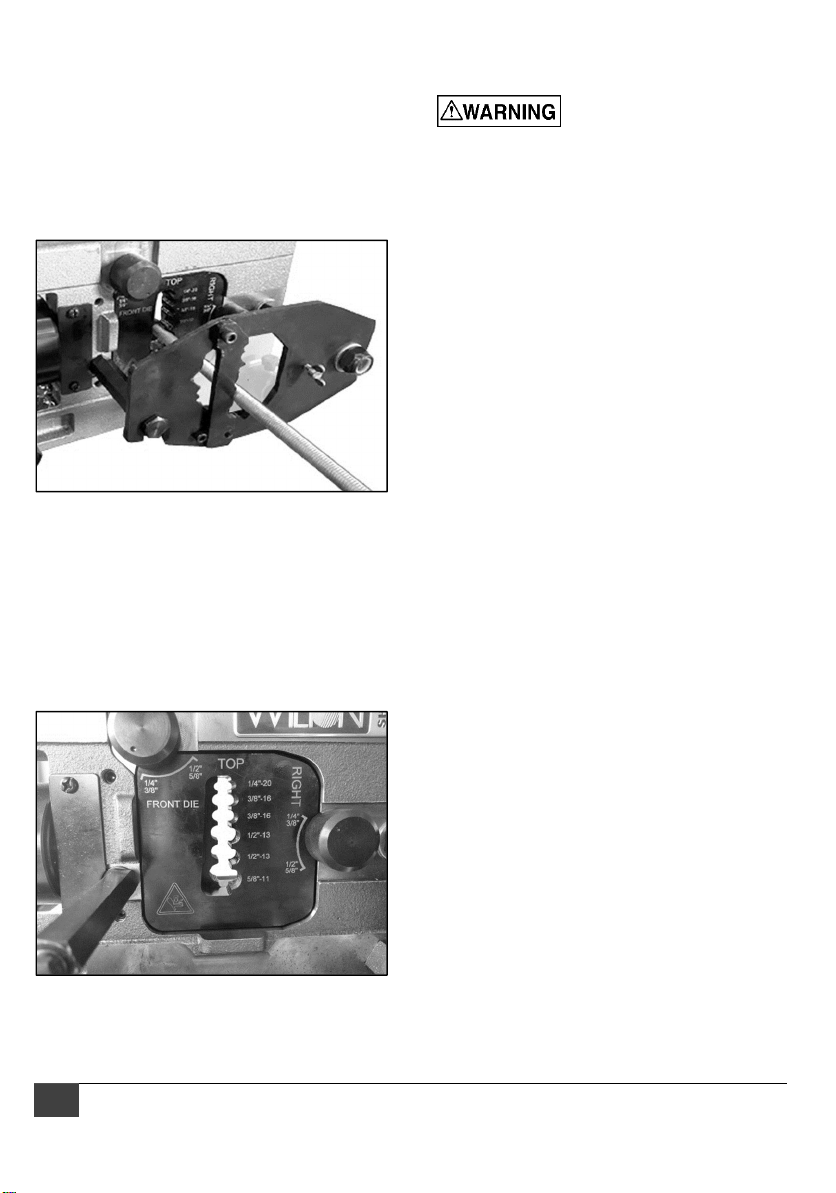
To cut threaded rod, loosen wing nut to release
end of threaded rod rest. See Figure 7. Place
threaded rod against the rest, in the curve
which matches the rod diameter. Slide the rod
through the matching slot in the blade.
NOTE: Cutting threaded rod requires the
threaded rod blade set (not provided; see sect.
10.0).
Figure 7
For threaded rod, there are two recommended
positions, as identified on the threaded rod blade
set. See Figure 8.
For 1/4 and 3/8 inch threaded rod, tighten locking
knob completely. For 1/2 and 5/8 inch rod, turn
locking knob slightly counterclockwise till the
debossed reference point on knob aligns with
indicator line on blade.
9.0 User-maintenance
hydraulic source before performing any
cleaning or maintenance of the unit.
Periodically apply a light coat of machine oil to
exposed metal areas, such as rods, to inhibit
rust.
Periodically inspect tightness of knurled
locking knobs which secure blades to frame.
If cutting becomes difficult, remove stationary
die and clear away any shavings from cutting
area, using vacuum or brush. Do not use bare
hands.
Periodically clean and lubricate the cutting die
blade edge with machine tool oil.
9.1 Additional servicing
Any additional servicing should be performed
by authorized service personnel.
Disconnect from power/
Figure 8
8 WSHR-3017 Strut & Threaded Rod Shear
Page 9

10.0 Optional accessories for WSHR-3017
Table 2
Part No. Description
28990 Wilton SHR™ Power Pack, 30 Ton, 10,000 psi
28930 Wilton SHR™ Standard Blade Set (1-5/8" x 1-5/8" & 13/16" x 1-5/8")
28931 Wilton SHR™ Blade Set B-Line 4D21 (1-1/16" x 2-1/8")
28932 Wilton SHR™ Blade Set B-Line 4D22 (2-1/8" x 2-1/8")
28933 Wilton SHR™ Threaded Rod Blade Set (1/4"-20, 3/8"-16, 1/2"-13, 5/8"-11)
28934 Wilton SHR™ Blade Set Back to Back Strut (1-5/8" x 3-1/4")
28935 Wilton SHR™ Blade Set Deep Only (1-5/8" x 1-5/8")
All blade sets include fixed die and moving die.
11.0 Compatibility chart
Table 3
The Wilton Strut and Threaded Rod Shear is compatible with the following products.
Wilton
blade set
28930
(standard)
28931 B-Line® 4D21
28932 B-Line® 4D22
28933 All mild steel rod
28934
(back-to-back)
28935
(deep only)
Brand Compatible strut
P1000, P1100, P1000T, P1000SL, P1000HS, P1000H3, P2000 &
®
Unistrut
B-Line®
Powerstrut® PS200, PS210 & PS560, PS500, PS520
Superstrut® A1200, A1400 & B-1200, B1400
Unistrut
B-Line® B22A, B24A, B26A
Powerstrut® PS 200 2T3, PS 210 2T3
Superstrut® A-1202
Unistrut
B-Line® B-Line B22, B24, B26
Powerstrut® PS200, PS210
Superstrut® A1200, A1400
P4520, P4000, P4100, P4100, P4100T, P4100SL, P4100HS
B-Line B22, B24, B26 & B52, B54, B56
B22, B22SH, B22S, B22H17/8, B22TH, B22S58,
B24, B24SH, B24S, B24H17/8, B24TH, B24S58,
B52, B52SH, B52S, B52H17/8, B52TH, B52S58,
B54, B54SH, B54S, B54H17/8, B54TH, B54S58
®
P1001, P1101, P2001
®
P1100, P1000T, P1000SL, P1000HS, P1000H3, P2000
WILTON 9
Page 10

12.0 Troubleshooting WSHR-3017
Table 4
Problem Possible cause Remedy
Irregular cut. Stock rest not adjusted properly.
Adjust stock rest so that strut is
perpendicular to cutting die
surface. Ensure that knobs are
tightened down on guide bars.
Hydraulic ram won’t
move, or produces
insufficient pressure.
Shear blade won’t
return to rest
position.
Strut will insert
through fixed die,
but won’t go through
cutting die.
Locking knobs which hold die in
frame of main unit have loosened
(possibly from vibration over longterm use).
Error with hydraulic source. Consult hydraulic pump
Hydraulic dump valve not
functioning.
Blade movement blocked by
obstruction.
Cutting die is too far forward. Turn adjustment screw on
Strut is slightly curved or deformed.
(Back-to-back strut is sometimes
more susceptible to this.)
Check tightness of locking knobs
after about every 100 cuts.
manufacturer’s documentation to
troubleshoot.
Inspect and correct dump valve
function on hydraulic system.
Clean debris from blade area.
cylinder to move the start
position of cutting die, until strut
can enter. (5mm hex wrench
required.)
10 WSHR-3017 Strut & Threaded Rod Shear
Page 11

13.0 Replacement Parts
To order parts or reach our service department, call 1-800-373-8206 Monday through Friday, 8AM to
5PM CST. Having the Model Number and Serial Number of your machine available when you call will
allow us to serve you quickly and accurately.
Some parts are shown for reference only, and may not be available individually.
Non-proprietary parts, such as fasteners, can usually be found at local hardware stores or may be
ordered from Wilton.
WILTON 11
Page 12

13.1 WSHR-3017 exploded view
12 WSHR-3017 Strut & Threaded Rod Shear
Page 13

13.2 WSHR-3017 parts list
Index Part No. Description Qty
1 TS-1506091 Socket Head Cap Screw M12 x 1.75P x 60L 2
2 TS-2361121 Lock Washer M12 2
3
WSHR3017-103
4 WSHR3017-104 Handle 1
5 TS-1505021 Socket Head Cap Screw M10 x 1.5P x 20L 2
6 WSHR3017-106 Cylinder 1
7 WSHR3017-107 Push Block 1
8 TS-2361081 Lock Washer M8 4
9 WSHR3017-109 Socket Head Cap Screw
10 TS-1550041 Flat Washer 6.5 x 16 x 1T 5
11 WSHR3017-111 Linking Plate 1
12 TS-1503011 Socket Head Cap Screw M6 x 1.0P x 8L 2
13 TS-0680021 Flat Washer 1/4 IN x 25 x 2L 1
14 WSHR3017-114 Compression Spring 1
15 WSHR3017-115 Knob M6 x 1.0P x 15L 1
16 WSHR3017-116 Index Pin 1
17 TS-1550061 Flat Washer 8 x 18 x 2T 1
18 F009925 Socket Head Button Screw M8 x 1.25P x 45L 1
19 TS-2248302 Socket Head Button Screw M8 x 1.25P x 30L 1
20 WSHR3017-120 Ball Plunger M10 x 1.5P x 20L 2
21 WSHR3017-121 Safety Guard 1
22 TS-1534032 Phillips Pan Hd Machine Screw M6 x 1.0P x 10L 2
23 WSHR3017-123 Knob Screw M6 x 1.0P x 13L 2
24 WSHR3017-124 Guide Bushing 2
25 TS-2311081 Hex Nut M8 x 1.25P 2
26 WSHR3017-126 Compression Spring 2
27 WSHR3017-127 Lock Knob 2
28 28930 Standard Blade Set
29 TS-2360121 Flat Washer 12 x 23 x 2T 1
30 WSHR3017-130 Stock Rest Support Rod 1
31 TS-1541021 Nylon Lock Hex Nut M6 x 1.0P 3
32 WSHR3017-132 Stock Rest for Strut 1
33 TS-1503051 Socket Head Cap Screw M6 x 1.0P x 20L 1
34 WSHR3017-134 Stock Rest for Threaded Rod 1
35 WSHR3017-135 Wing Screw M6 x 1.0P x 16L 1
36 TS-2342161 Nylon Lock Hex Nut M16 x 2.0P 1
37 WSHR3017-137 Flat Washer 17 x 33 x 2T 3
38 WSHR3017-138 Stock Rest Pivot Rod 1
39 TS-1523011 Socket Head Set Screw M6 x 1.0P x 6L 4
40 TS-2361161 Lock Washer M16 1
41 TS-2311161 Hex Nut M16 x 2.0P 1
42 WSHR3017-142 Stock Stop Base 2
43 WSHR3017-143 Left Tube Plug 2
44 WSHR3017-144 Special Screw M8 x 1.25P x 23L 4
45 WSHR3017-145 Compression Spring 4
Body Frame 1
M8 x 1.25P x 45L (thread
length 30L)
1-5/8” x 1-5/8” and 13/16”
x 1-5/8"
1
1
WILTON 13
Page 14

46 WSHR3017-146 Knob M6 x 1.0P x 18L 4
49 WSHR3017-149 Stock Stop Sliding Bar with Scale 2
50 WSHR3017-150 Scale 2
51 WSHR3017-151 Right Tube Plug 2
52 TS-1482051 Hex Cap Screw M6 x 1.0P x 25L 2
53 WSHR3017-153 Stock Stop Holding Bracket 1
54 WSHR3017-154 Spacer 2
55 WSHR3017-155 Nylon Washer 2
56 WSHR3017-156 Stock Stop 1
57 WSHR3017-157 Wing Screw M6 x 1.0P x 16L 1
58 WSHR3017-158 Scale Pointer 1
59 6290832 Phillips Pan Hd Machine Screw M5 x 0.8P x 8L 2
LM000428 Warning Label (not shown) 1
LM000429 ID Label (not shown) 1
LM000430 Wilton Nameplate Label (not shown) 1
14 WSHR-3017 Strut & Threaded Rod Shear
Page 15

14.0 Warranty and Service
Wilton® warrants every product they sell against manufacturers’ defects. If one of our tools or machines needs
service or repair, please contact Technical Service by calling 1-800-373-8206, 8AM to 5PM CST, Monday through
Friday.
Warranty Period
The general warranty lasts for the time period specified in the literature included with your product or on the official
Wilton branded website.
Wilton products carry a limited warranty which varies in duration based upon the product. (See chart
below)
Accessories carry a limited warranty of one year from the date of receipt.
Consumable items are defined as expendable parts or accessories expected to become inoperable
within a reasonable amount of use and are covered by a 90 day limited warranty against manufacturer’s
defects.
Who is Covered
This warranty covers only the initial purchaser of the product from the date of delivery.
What is Covered
This warranty covers any defects in workmanship or materials subject to the limitations stated below. This warranty
does not cover failures due directly or indirectly to misuse, abuse, negligence or accidents, normal wear-and-tear,
improper repair, alterations or lack of maintenance.
How to Get Technical Support
Please contact Technical Service by calling 1-800-373-8206. Please note that you will be asked to provide
proof of initial purchase when calling. If a product requires further inspection, the Technical Service
representative will explain and assist with any additional action needed. Wilton has Authorized Service Centers
located throughout the United States. For the name of an Authorized Service Center in your area call 1-800-2746846 or use the Service Center Locator on the Wilton website.
More Information
Wilton is consistently adding new products. For complete, up-to-date product information, check with your local
distributor or visit the Wilton website.
How State Law Applies
This warranty gives you specific legal rights, subject to applicable state law.
Limitations on This Warranty
WILTON LIMITS ALL IMPLIED WARRANTIES TO THE PERIOD OF THE LIMITED WARRANTY FOR EACH
PRODUCT. EXCEPT AS STATED HEREIN, ANY IMPLIED WARRANTIES OF MERCHANTABILITY AND
FITNESS FOR A PARTICULAR PURPOSE ARE EXCLUDED. SOME STATES DO NOT ALLOW LIMITATIONS
ON HOW LONG AN IMPLIED WARRANTY LASTS, SO THE ABOVE LIMITATION MAY NOT APPLY TO YOU.
WILTON SHALL IN NO EVENT BE LIABLE FOR DEATH, INJURIES TO PERSONS OR PROPERTY, OR FOR
INCIDENTAL, CONTINGENT, SPECIAL, OR CONSEQUENTIAL DAMAGES ARISING FROM THE USE OF OUR
PRODUCTS. SOME STATES DO NOT ALLOW THE EXCLUSION OR LIMITATION OF INCIDENTAL OR
CONSEQUENTIAL DAMAGES, SO THE ABOVE LIMITATION OR EXCLUSION MAY NOT APPLY TO YOU.
Wilton sells through distributors only. The specifications listed in Wilton printed materials and on official Wilton
branded website are given as general information and are not binding. Wilton reserves the right to effect at any
time, without prior notice, those alterations to parts, fittings, and accessory equipment which they may deem
necessary for any reason whatsoever.
Product Listing with Warranty Period
90 Days – Parts; Consumable items, including Blade Sets
1 Year – Wilton SHR™ Strut & Threaded Rod Shear
NOTE: Wilton is a division of JPW Industries, Inc. References in this document to Wilton also apply to JPW
Industries, Inc., or any of its successors in interest to the Wilton brand.
WILTON 15
Page 16

427 New Sanford Road
LaVergne, Tennessee 37086
Phone: 800-373-8206
www.wiltontools.com
16 WSHR-3017 Strut & Threaded Rod Shear
 Loading...