

Page 1
Operat ing I nstructi ons
& Service Parts Manual
All Terrain Vise
# 10010
Record purchase infor m ation for quick reference:
WILTON
427 New Sanford Road
LaVergne, Tennessee 37086
Ph.: 800-274-6848
www.wiltontools.com
Manual No. M-10010
Rev B 08/2014
Copy r ight © 2014 , WILTON
Page 2

Warranty and Service
Wilton® warrants every product they sell against manufacturers’ defects. If one of our tools needs service or repair, please
contact Technical Service by calling 1-800-274-6846, 8AM to 5PM CST, Monday through Friday.
Warranty Period
The general warranty lasts for the time period specified in the literature included with your product or on the official Wilton
branded website.
• Wilton products carry a limited warranty which varies in duration based upon the product. (See chart below)
• Accessories carry a limited warranty of one year from the date of receipt.
• Consumable items are defined as expendable parts or accessories expected to become inoperable within a
reasonable amount of use and are covered by a 90 day limited warranty against manufacturer’s defects.
Who is Covered
This warranty covers only the initial purchaser of the product from the date of delivery.
What is Co vered
This warranty covers any defects in workmanship or materials subject to the limitations stated below. This warranty does not
cover failures due directly or indirectly to misuse, abuse, negligence or accidents, normal wear-and-tear, improper repair,
alterations or lack of maintenance.
How to Get Technical Support
Please contact Technical Service by calling 1-800-274-6846. Please note that you will be asked to provi d e pr o of of ini tial
purchase when calling. If a product requires further inspection, the Technical Service repr esenta tive will explain and assist
with any additional action needed. Wilton has Authorized Service Centers located throughout the United States. For the name
of an Authorized Service Center in your area call 1-800-274-6846 or use the Service Center Locator on the Wilton website.
More Information
Wilton is consistently adding new products. For complete, up-to-date product information, check with your local distributor or
visit the Wilton website.
How S tate Law Applies
This warranty gives you specific legal rights, subject to applicable state law.
Limitations on This Warranty
WILTON LIMITS ALL IMPLIED WARRANTIES TO THE PERIOD OF THE LIMITED WARRANTY FOR EACH PRODUCT.
EXCEPT AS STATED HEREIN, ANY IMPLIED WARRANTIES OF MERCHANTABILITY AND FITNESS FOR A PARTICULAR
PURPOSE ARE EXCLUDED. SOME STATES DO NOT ALLOW LIMITATIONS ON HOW LONG AN IMPLIED WARRANTY
LASTS, SO THE ABOVE LIMITATION MAY NOT APPLY TO YOU.
WILTON SHALL IN NO EVENT BE LIABLE FOR DEATH, INJURIES TO PERSONS OR PROPERTY, OR FOR INCIDENTAL,
CONTINGENT, SPECIAL, OR CONSEQUENTIAL DAMAGES ARISING FROM THE USE OF OUR PRODUCTS. SOME
STATES DO NOT ALLOW THE EXCLUSION OR LIMITATION OF INCIDENTAL OR CONSEQUENTIAL DAMAGES, SO THE
ABOVE LIMITATION OR EXCLUSION MAY NOT APPLY TO YOU.
Wilton sells through distributors only. The specifications listed in Wilton printed materials and on official Wilton branded
website are given as general information and are not binding. Wilton reserves the right to effect at any time, without prior
notice, those alterations to parts, fittings, and accessory equipment which they may deem necessary for any reason
whatsoever.
Product Listing with Warranty Period
90 Days – Parts; Consumable items
Limited Lifetime – Wilton branded products
NOTE: Wilton is a div ision o f JPW Ind u strie s , In c. Reference s in this doc umen t to Wilto n a ls o apply to JPW Industrie s, In c.,
or any of its successors in interest to the Wilton brand.
2
Page 3
Read and understand the entire owner's manual before attempting i nstallation or operation.
Warnings
1. Keep hands clear of jaws.
2. Make sure vise is properly secured to hitch receiver. If using accessory bench receiver, vise must be properly
secured within receiver, and receiver bolted to bench with appropriate fasteners (not included).
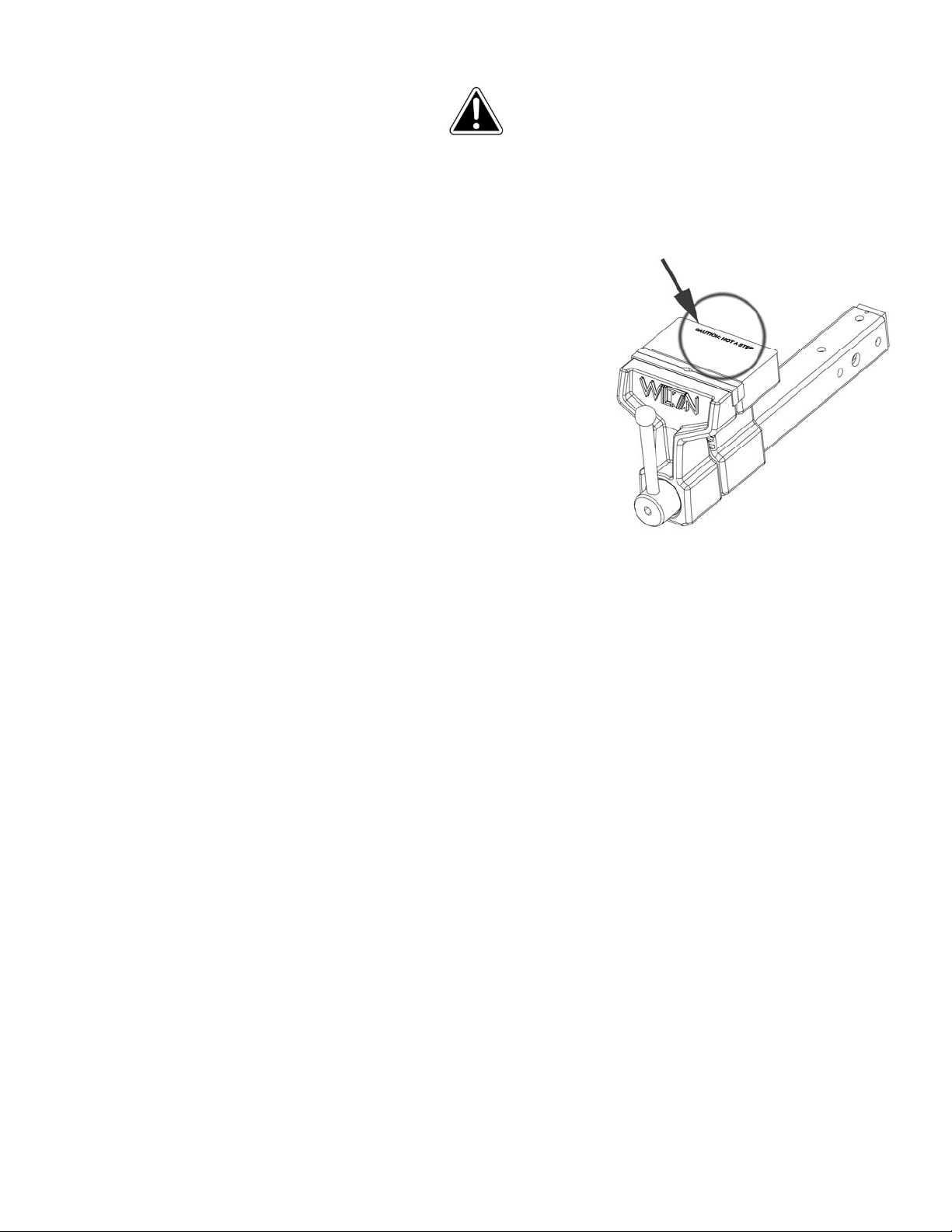
3. Do not use the vise as a step; it m ay cause an i ndi vidual to sl i p and
fall. This caution is also inscribed in the anvil of the vise – see
Figure 1.
4. Keep ground or floor around the v ise unclutter ed and free of scrap
material, oil and grease. Wear non-slip footwear.
5. Do not place combustible materials or pressurized containers in
vise.
6. Do not for ce the tool. Do not use a hamm er against the handl e, or
use additi onal lev er age s uch as che ater bar s or p ipe ex tensio ns, to
tighten the screw handle. For heavier jobs, use a larger vise.
7. Vehicle safety brake must be engaged before operating vise.
8. Do not drive vehicle with material in the vise.
9. Use caution when backing a vehicle with the vise installed.
10. Make sure v ise handle is l ocked and hitch pi n is properl y engaged
before driving vehicle.
11. Read and understa nd all warni ngs posted on the vise and in thi s manual. Fail ure to comply wit h all of these
warnings may cause serious injury.
12. Do not use this vise for other than its intended use.
13. Replace warning labels if they become obscured or removed.
14. Always wear ANSI- approved safety glas ses or face shield w hen using striking or power tools with this vise.
(Ever yday eyeglas ses onl y hav e imp act res istant lens es; the y are not saf et y gl asses. ) W ear hearing protecti on
when needed.
15. Do not wear loose clothing or jewelry. Confine long hair. Keep clothing, hair and gloves away from moving
parts.
16. Some dust created by power sanding, sawing, grinding, drilling and other construction activities contain
chemicals known to cause cancer, birth defects or other reproductive harm. Some examples of these
chemicals are:
• Lead from lead based paint.
• Crystalline silica from bricks, cement and other masonry products.
• Arsenic and chromium from chemically treated lumber.
Your ris k of exposure v aries, depending on how often you do this t ype of work . To reduce your exp osure to
these chemicals, w ork i n a well-v ent il at ed ar ea a nd work with approved saf ety eq ui pment, such as face or dus t
masks that are specifically designed to filter out microscopic particles.
Figure 1
17. Alw ays insp ect v i se bef ore use. C heck f or m is alignm ent of m oving p arts , bindi ng of moving par ts, br eakag e of
parts, mounting and any other conditions that may affect the tool’s operation. If damage is found, repair the vise
immediately or replace it.
18. Have tool serviced only by qualified personnel, using authorized replacement parts.
3
Page 4

19. Provide for adequate space surrounding work area and sufficient lighting.
20. Do not use this tool while tired or under the influence of drugs, alcohol or medication.
21. Keep bystanders, especially children, away from the area while using the vise.
22. Giv e your work undivi ded attentio n. Looking around, carrying on a conver sation a nd “horse- play” ar e car eless
acts that can result in serious injury.
23. Maintain a balanced stance at all times. Do not overreach while performing the work.
About this vise
The WILTON Al l Terrain Vise has b een des i g ned an d c onst r uct ed t o p rovide cons i st ent l ong - term operation,
if used i n accordance w ith instructi ons as set f orth in this document. The b ody is form ed of high-s trength
ductile cas t ir on. The leadscr ew is prec isi on ground car b on steel w ith acm e threads. The tub e has adj ust ing
screws top and side for el iminating play ins ide the hitch rec eiver. The handle c an be repositi oned without
moving the jaws.
About this manual
This manual covers operation and maintenance procedures for a WILTON All Terrain Vise. It contains
instruct ions on inst allati on, saf ety precaut ions, g eneral operati ng proc edures, m aintenance ins tructi ons and
parts breakdown.
The instr uctions and war nings presented i n this manual can not, of cour se, cover all possible sit uations or
conditions in which a vise may be used. The operator is expected to take appropriate precautions and
exercis e common sens e. As with an y tool op eration, s afety of t he operat or and b ystanders sho uld be f irst
priority.
If there ar e questions or c om ments, pl eas e cont act your l oc al supplier or W il ton. Wilton can als o b e r eached
at our web site: www.wiltontools.com.
Retain this manual for future reference. If the tool transfers ownership, the manual should accompany it.
Read and understand the entire contents of this manual before installing or using
the All Terrain Vise. Failure to comply may cause serious injury.
Specifications
Model .............................................................................................................................. WILTON All Terrain Vise
Stock number............................................................................................................................................... 10010
Required hitch receiver........................................................................................................................2 in. square
Jaw width ..................................................................................................................... ................... 150 mm (6 in.)
Maximum jaw opening .............................................................................................................. 145 mm (5-3/4 in.)
Jaw insert hardness ............................................................................................................................. 45-56 HRC
Pipe capacity ..................................................................... 3/4 - 3 in. (or 1/2 - 3 in. with one jaw insert removed)
Clamping force................................................................................................................................................1 ton
Throat depth ................................................................................................................................... 127 mm (5 in.)
Jaw travel per one rotation of handle ............................................................................................ 4 mm (0.15 in.)
Weight ........................................................................................................................................... 18 kg (39.68 lb)
Dimensions ....................................................................................... 489 x 150 x 185 mm (19-1/4 x 6 x 7-1/4 in.)
Primary materials .................................................................................................................. steel and ductile iron
Paint finish ............................................................................................................................. powder coat enamel
The specifi cations i n this manual wer e current at ti me of publ ication, bu t because of our pol icy of cont inuous
improve ment, W ilton reserves t he right to chan ge specific ations at any ti me and without pr ior notice, w ithout
incurring obligations.
4
Page 5

Setup and assembly
Read and understand all
instructions and warnings in this manual before
attempting installation or operation of hitch vise.
Failure to comply may cause serious injury.
Shipping contents
1 Vise
1 Hitch pin with cotter pin
1 Bench mount receiver
1 Instructions and parts manual
1 Warranty card
Remov e contents f r om ship pi ng cart on, and chec k f or
shippi ng dam age or mis sing par ts. If either of thes e is
discovered, contact your dealer or Wilton at the phone
number on the cover.
Installing to hitch
Refer to Figure 2.
The All Terr ain Vise is desi gned to be inser ted into a
2-inch square hitch receiver.
1. Slide v ise tube into receiv er. If there i s too much
“play” within the receiver, remove the vise and
rotate any of four screws (A) on the vise tube, with
a 5/16” hex ke y. Reinstall and test f or fit, m aking
further adjustments as needed.
Installing to bench/table
Bench or table must be capable of supporting
combined weight of vise, workpiece and applied
forces. If additional strength is needed, mount
supporting boards beneath the table.
Refer to Figures 3 and 4.
1. Position vise on bench. The rear (or static) jaw
should just overhang the bench to prevent
obstruction when inserting long work pieces.
2. Place bench receiver over vise tube and mark
hole positions on bench. Figure 3 identif ies hole
dimensions . Drill holes of app ropriate diam eter in
table.
3. Mount b ench receiv er to bench usi ng fastener s of
suitable grade, length and diameter. The hole in
the side of the receiver should be at the end
farthest from the vise.
4. Slide v ise tube into bench r eceiver. If ther e is too
much “p lay” within the r eceiver, r otate any of t he
four adjustment screws on the tube (A, Figure 2).
5. Install hitch p i n through holes of tub e a nd r ec ei ver
(Figure 4).
6. Install cotter pin into hitch pin hole.
2. Align hole in vise tube with hole in hitch receiver.
3. Insert hitch pin (B) completely through receiver
and vise tube.
4. Install cotter pin (C) through hole in hitch pin.
Cotter pin must be properly
secured in hitch pin before operating vise or
moving vehicle to which vise is moun ted.
Figure 2
Figure 3 (dimensions in millimeters)
Figure 4
5
Page 6

Adjustments and Operation
Before use, inspect the vise for cracks, misalignment,
binding , or any other probl ems that may com promise
its safe use.
Handle adjustment
To operate the hitch vise:
1. Turn screw handle counterclockwise to open
jaws. Do not try to force jaws apart farther than
the rated capacity/jaw opening.
2. Choose the straight jaws or pipe jaws. Insert
workpiece and turn handle clockwise to close
jaws.
Refer to Figure 5.
The handle hub is spring-loaded, and allows the
handle to be repositioned without moving the jaws.
After securing the workpiece in the jaws, grasp handle
hub and pull out. Rotate handle hub to desired
position, then release.
Figure 5
3. Tighten enough that w orkpiece can no longer be
shifted w ithi n the jaw s. Do not ov erti ghten, as this
may damage workpiece and/or jaws.
Maintenance
Inspection: Before use, inspect vise for
misalignment, binding or cracked/damaged parts, or
any other condition that may affect safe operation.
Repair or replace a damaged vise.
Cleaning: After use, wipe external surfaces of the
vise w i th a c l ean r ag . Apply a l i g ht c oat of machi ne oi l
to exposed metal areas.
Lubrication: The leadscrew i s permanently lub r i cat ed
and enclosed, and should not require attention.
Lubric ate other m ov ing par ts of the v i se wi th machine
oil.
Jaw insert replacement: Use a 5mm hex key to
remov e tw o s crew s on t he j aw insert. Sec ur el y tig ht en
the new jaw insert to the vise using the same screws.
NOTE: If replacing jaw inserts, replace both as a set.
Replacement Parts
To order parts or reach our service department, call 1-800-274-6848 Monday through Friday, 8AM to 5PM CST.
Having the Model Number and Seri al Number of your machine av ailabl e when you call will allow us to serv e you quick ly
and accuratel y .
6
Page 7

WILTON All Terrain Vise #10010 – Expl oded View
WILTON All Te rrain Vise #10010 – Parts List
Index No Part No Description Size Qty
..................... ATV-HA ................... H andle Assembly (index #1- 5) ....................... .................................................... 1
1 ................... ATV-01 .................... Ca p ............................................................... .................................................... 1
2 ................... A TV-02 .................... Handle ......................................................... .................................................... 1
3 ................... A TV-03 .................... Socket Head Cap Screw................................ .................................................... 1
4 ................... ATV-04 .................... Washer ......................................................... Ø11 x Ø20x 2 mm ........................ 1
5 ................... ATV-05 .................... Spring ........................................................... Ø16x22 mm ................................. 1
9 ................... ATV-09 .................... Se t Screw ...................................................... .................................................... 2
10 ................. ATV-10 .................... Spin dle Co llar ................................................ .................................................... 1
11 ................. ................................ Lead Screw (Re: A TV-11) .............................. .................................................... 1
12 ................. ................................ Floating Jaw Body ......................................... .................................................... 1
13 ................. ATV-13 .................... Jaw Insert (set of 2) ....................................... 6”L x 1/2"W x 7/8”H ................ 1 set
14 ................. TS-1503031 ............. Socket Head Cap Screw................................ M6x12 .......................................... 4
15 ................. ................................ Stationary Jaw Body ...................................... .................................................... 1
16 ................. ATV-16 .................... Hitch Pin ....................................................... Ø16 mm ....................................... 1
17 ................. ATV-17 .................... Cotter Pin ...................................................... Ø4 mm ......................................... 1
18 ................. ATV-23 .................... Adjust ment Screw ......................................... .................................................... 4
19 ................. ATV-18 .................... Roll Pin ......................................................... 4x12 mm ...................................... 2
20 ................. ATV-19 .................... Spin dle Nu t ................................................... .................................................... 1
21 ................. ATV-20 .................... Spacer .......................................................... ........... ......................................... 1
22 ................. JHM610-22 .............. Socket Head Cap Screw................................ M6x14 .......................................... 1
23 ................. 10300 ...................... Bench Mount Receiver .................................. .................................................... 1
24 ................. ................................ Handle Pi n (Re: ATV - 11) ............................... .................................................... 1
25 ................. ................................ Hexagonal Collar (Re: ATV- 11) ..................... .................................................... 1
26 ................. ATV-11 .................... Lead Screw Assembly (index #11,24,25) ....... .................................................... 1
Some parts are shown for refer enc e only and may not be available as replacem ent parts.
7
Page 8

427 New Sanford Road
LaVergne, Tennessee 37086
Phone: 800-274-6848
www.wiltontools.com
8
 Loading...