

Page 1
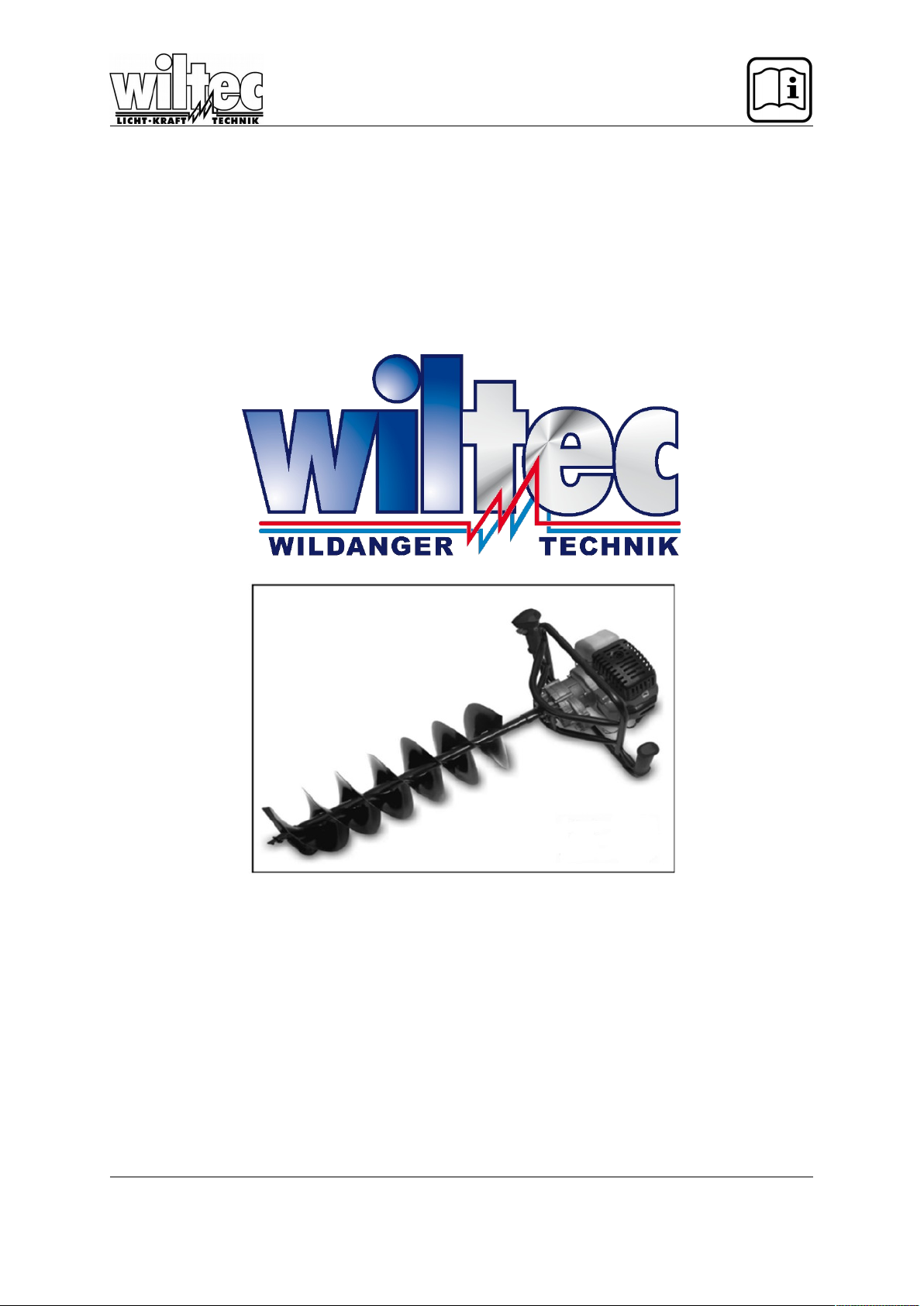
Operation Manual
Post Hole Digger
ARTICEL 61197
Read and follow the operating instructions and safety information before using for the first time.
Technical changes reserved!
Due to further developments, illustrations, functioning steps and technical data can differ
insignificantly.
Updating the documentation
If you have suggestions for improvement or have found any irregularities please contact us.
© by WilTec Wildanger Technik GmbH Seite 23
http://www.WilTec.de
http://www.aoyue.eu
http://www.teichtip.de
Page 2

The information contained in this document is subject to change without prior notice. No part of this
document can be copied or duplicated in another form without the prior written consent of WilTec
Wildanger Technik GmbH. The WilTec Wildanger Technik GmbH assumes no liability for any errors in
this user manual or the connection diagram.
Although WilTec Wildanger Technik GmbH has made every effort to make sure that this user manual
is complete, accurate and updated, errors cannot always be avoided. In the event of problems with
this user manual please complete and send this form back to us.
FAX-notification (+++49 2403 55592-15),
from: ________________________________________
Name: ________________
Firm:_____________________
Tel/Fax:__________________
I would like to report the following mistakes:
_______________________________ ____________________________________
Customer Service WilTec Wildanger Technik GmbH
e-mail: [email protected]
Tel:++ +49 2403 55592-0
Introduction
Thank you for purchasing this quality product. To minimize the risk of injury by means of fire or
electric shock we urge that our clients take some basic safety precautions when using this
device. Please read the operation instructions carefully and make sure you have understood its
content.
Always use a grounded power connection with the appropriate mains voltage. You can
nd the corresponding mains voltage on the type plate. If you have any doubts about the
connection being grounded, have it checked by a qualied professional. Never use a
faulty electric cable.
Do not inspect the electrical part of the pressure pond lter in a wet or damp
environment or when you are wet yourself and protect it from direct sunlight. Install this
device in a safe location so that nobody can step on the cable, fall over or damage it.
Disconnect the power plug before cleaning it and use only a damp cloth for cleaning.
Avoid using cleaning agents and make sure that no liquid enters the electrical part of the pump.
The electric part of the device contains no parts that can be inspected or serviced by the user. Leave
the maintenance, adjustment and repair to qualified technical personnel. In case of unauthorised
intervention the 2-year warranty is no longer valid! Keep these operation instructions safe.
© by WilTec Wildanger Technik GmbH Seite 24
http://www.WilTec.de
http://www.aoyue.eu
http://www.teichtip.de
Page 3

IMPORTANT!
IT IS ESSENTIAL THAT YOU READ THE INSTRUCTIONS IN THIS
MANUAL BEFORE OPERATING THIS MACHINE
© by WilTec Wildanger Technik GmbH Seite 25
http://www.WilTec.de
http://www.aoyue.eu
http://www.teichtip.de
Page 4
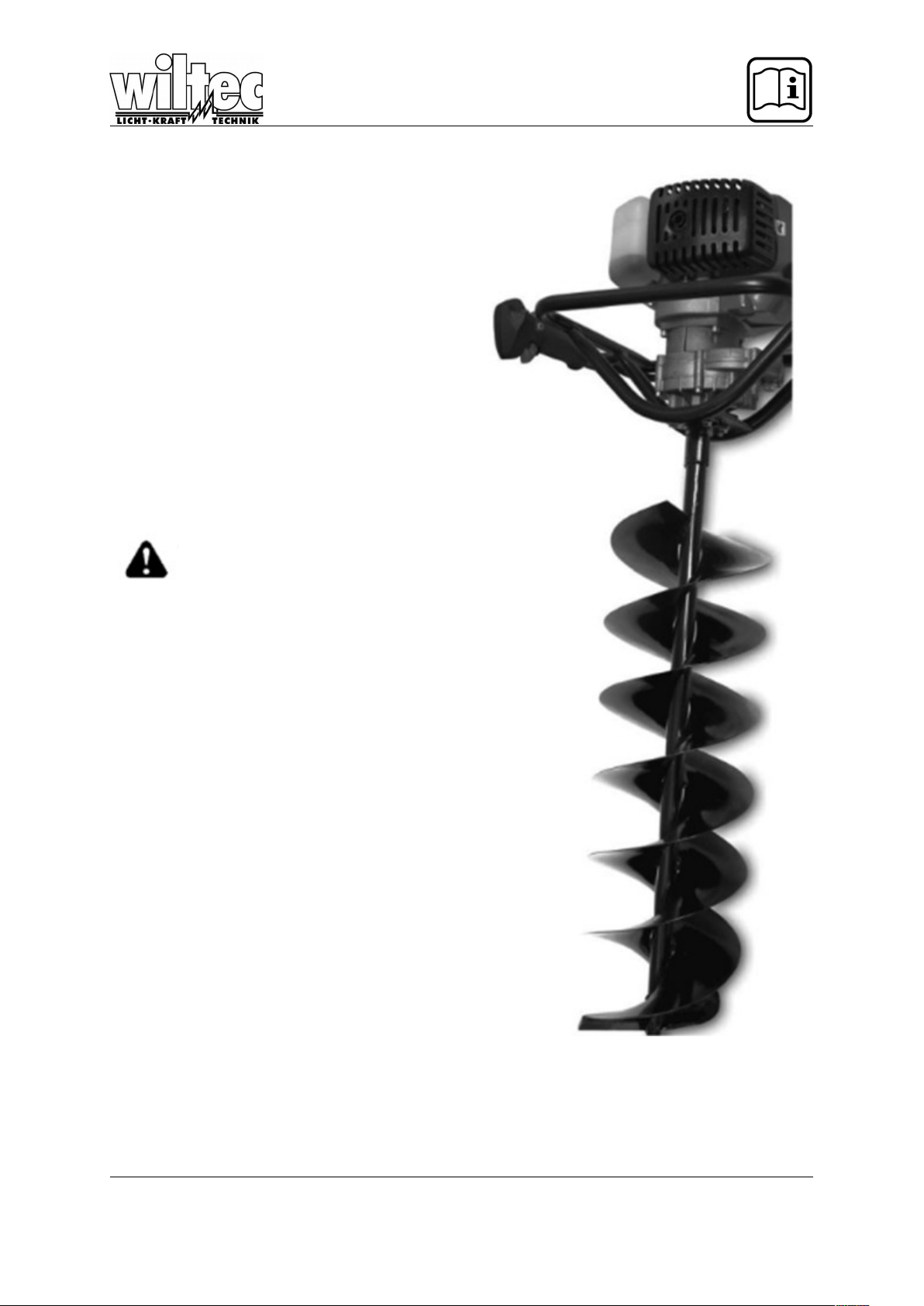
Thank you for
buying a our
post hole digger!
Your new tool has been engineered and manufactured our high standard for dependability, ease of
operation and operator safety. With proper care it
will give you years of rugged, trouble-free performance.
For your own safety please read and understand this operator’s manual before attempting
to operate your post hole digger.
WARNING!
To reduce the risk of injury, the user
must read and understand the operator’s manual.
Do not attempt to operate this post hole
digger until you have read thoroughly
and understood completely all instructions and safety rules contained in this
manual. Failure to comply may result in
accidents involving fire, electric shock
or serious personal injury. Save the operator’s manual and review it frequently
to be able to continue a safe operation
and instruct others who use this tool.
© by WilTec Wildanger Technik GmbH Seite 26
http://www.WilTec.de
http://www.aoyue.eu
http://www.teichtip.de
Page 5

PLEASE READ ALL INSTRUCTIONS AND FOLLOW WARNINGS
GENERAL SAFETY RULES
For safe operation read and understand all instructions before using the post hole digger. Follow
all safety instructions. Failure to follow all safety instructions below can result in serious personal
injury.
Do not allow children or untrained individuals to use this unit.
The power drill must only be used by adults in good physical condition with knowledge of the op-
erating instructions.
Never start or run the engine in a closed or poorly ventilated area; breathing exhaust fumes can
kill.
Clear the work area before each use. Remove all objects such as rocks, broken glass, nails, wires
or strings which can become entangled in the auger.
Wear protective non-slip safety-shoes, gloves, glasses and ear protection while operating this
unit.
Wear heavy long pants. Do not wear loose clothing, short pants, loose jewelry of any kind, or use
with bare feet.
Secure long hair to prevent entanglement in any moving parts.
Keep all bystanders, children and pets at least 3m away.
Do not operate this unit when you are tired, ill or under the influence of alcohol, drugs or medica-
tion.
Do not operate in poor lighting.
Keep firm footing and balance. Do not overreach. Overreaching can result in loss of balance or
exposure to hot surfaces.
Keep all parts of your body away from any moving part.
Do not touch area around the muffler or cylinder of the post hole digger because these parts get
hot from operation.
Always stop the engine and remove the spark plug wire before making any andjustments or re-
pairs except for carburetor adjustments.
Inspect the unit before each use for loose fasteners, damaged components, fuel leaks or other
damages. Replace any damaged part before use.
It has been reported that vibrations from hand-held tools may contribute a condition called Ray-
naud’s Syndrome in certain individuals. Symptoms may include tingling, numbness and blanching
of the fingers, usually apparent upon exposure to cold. Hereditary factors exposure to cold and
dampness, diet, smoking and work practices are all thought to contribute to the development of
these symptoms. It is presently unknown what may contribute to the condition. There are mea-
sures that can be taken by the operator to possibly reduce the effects of vibrations:
© by WilTec Wildanger Technik GmbH Seite 27
http://www.WilTec.de
http://www.aoyue.eu
http://www.teichtip.de
Page 6

o Keep your body warm in cold weather. When operating the unit wear gloves to
keep the hands and wrists warm. It is reported that cold weather is a major fac-
tor contributing to Raynaud’s Syndrome.
o After each period of operation you should exercise to increase blood circulation.
o Take frequent work breaks. Limit the amount of exposure per day.
If you experience any of the symptoms of this condition immediately stop the use and see your
physician.
Keep the tool well maintained, fasteners tightened and worn parts replaced.
Mix and store fuel in a container approved for fuel.
Mix fuel outdoors where there are no sparks or flames. Wipe up any fuel spillage. Move 9m away
from refueling site before starting engine.
Stop the engine and allow it to cool before refueling or storing the unit.
Allow the engine to cool; empty the fuel tank and secure the unit from moving before transporting
in a vehicle.
SPECIFIC SAFETY RULES FOR POST HOLE DIGGER USE
Replace augers if cracked, bent or damaged in any way. Be sure the auger and or extension shaft
is properly installed and securely fastened. Failure to do so can cause serious injury.
Make sure all guards, straps, deflectors and handles are properly attached.
Do not start working until you have a clear work area. Do not work near electric cables or under-
ground utilities. It is highly recommended that you check with local authorities before starting to
drill.
If auger turns whilst the engine is idling, stop the engine and immediately adjust the idle settings
following the instructions in this manual.
Only use the manufacturer’s replacement augers on this unit. Do not use any other attachments.
Never operate until without the safety clutch in working condition. The safety clutch will engage
when the engine is at idle or if a hard object is struck.
Replace the bit immediately if any cracks or other damage are present.
Maintain a firm grip on both handles during operation.
Never use the drill with the handles above waist level. Drilling with the units handles above waist
level restricts control and can cause serious chest injuries if a hard object is struck.
Never carry the power drill with the engine running.
Carry the power drill with the engine stopped and with the auger bit removed.
© by WilTec Wildanger Technik GmbH Seite 28
http://www.WilTec.de
http://www.aoyue.eu
http://www.teichtip.de
Page 7
Never drill in horizontal angle. This drill should only be operated with the auger at a 90° angle to
the ground (see figure 7a, all figures are attached to this manual).
Always keep handles dry and clean.
Before starting to drill make sure the bit is not obstructed.
Always work in a firm-footed and safe position.
Never touch the auger bit or carry out maintenance with the engine running.
Grip the post hole digger firmly with both hands and keep all parts of the routine maintenance. For
other repairs, the tool must be serviced by an authorized person.
Store the power drill off the ground in a vertical position in a dry place and with fuel tank empty.
If the auger bit jams, stop the engine immediately.
Symbols
IMPORTANT: Some of the following symbols may be used on your tool. Please study them and learn
their meaning. Proper interpretation of these symbols will allow you to operate the tool better and
safer.
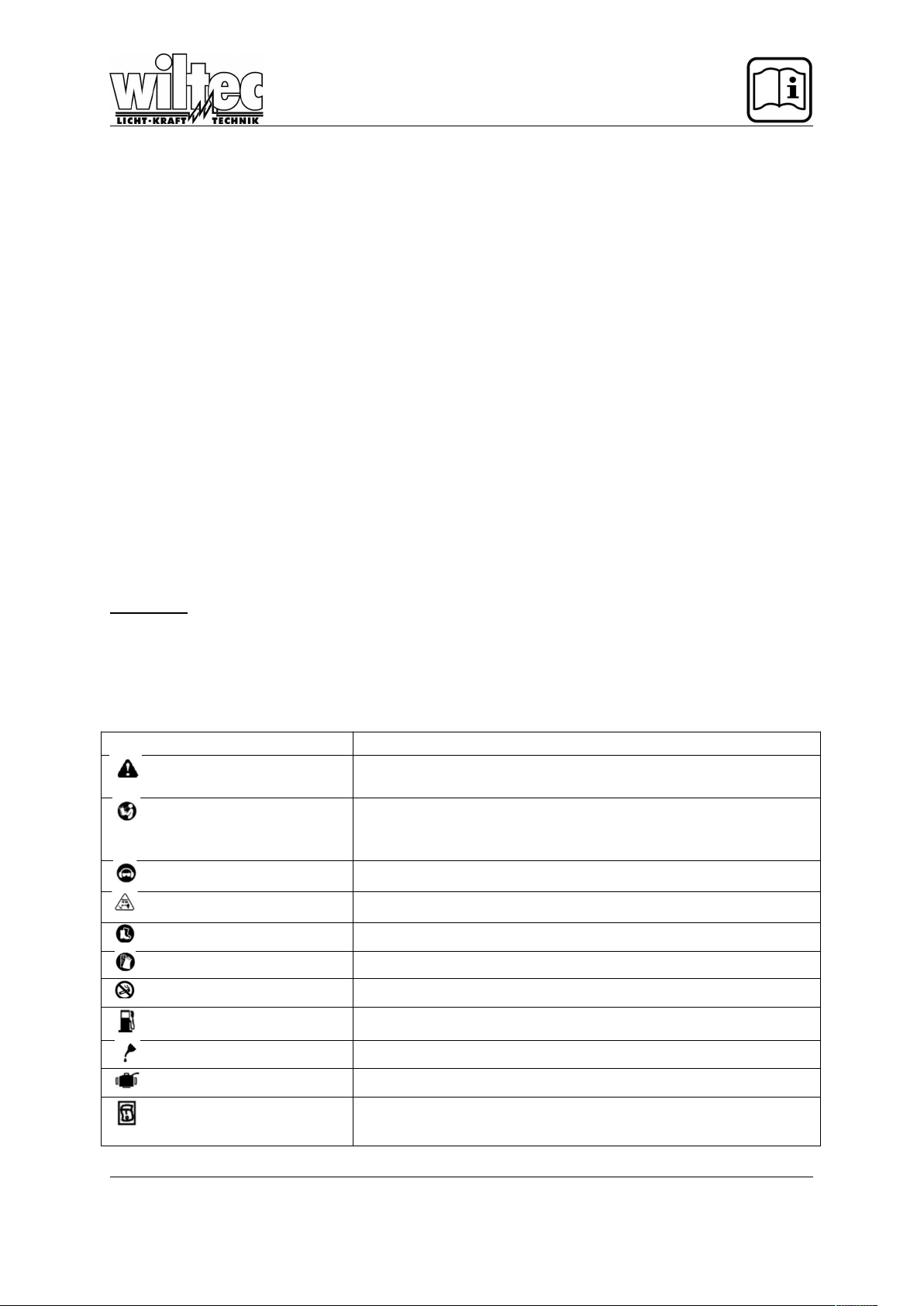
SYMBOL NAME EXPLANATION
Safety symbol Indicates danger, warning or caution. It means attention!!! Your safety is
involved.
Read your operators manual Your manual contains special message to bring attention to potential
safety concerns as well as operating and serving information. Please
read all information carefully to ensure safe use.
Eye and hearing protection Wear eye and hearing protection when operating this equipment.
Keep bystanders away
Keep all bystanders at least 3 m away.
Boots Wear non-slip safety footwear when using this equipment.
Gloves Wear non-slip, heavy-duty gloves.
No smoking Do not smoke when mixing fuel or filling fuel tank.
Petrol Use unleaded petrol intended for motor vehicle use with an octane rating
of 90 ([R+M]/2) or higher
Oil Use synthetic 2-stroke oil for air cooled engines.
Mix petrol and oil Mix the fuel mix thoroughly and also each time before refueling.
Switch On/Off Switch
I=ON to run
O=OFF to stop
© by WilTec Wildanger Technik GmbH Seite 29
http://www.WilTec.de
http://www.aoyue.eu
http://www.teichtip.de
Page 8

The following signal words and meanings are intended to explain the levels of risk associated with this
product.
SYMBOL SIGNAL EXPLANATION
Caution Indicates a potentially hazardous situation, which may result in minor or
moderate injury if not avoided.
Warning Indicates a potentially hazardous situation, which could result in death
or serious injury if not avoided.
Danger Indicates a potentially hazardous situation, which will result in death or
serious injury if not avoided.
(Without safety alert symbol) Indicates a situation that may result in
property damage.
© by WilTec Wildanger Technik GmbH Seite 30
http://www.WilTec.de
http://www.aoyue.eu
http://www.teichtip.de
Page 9
Service
Servicing requires extreme care and knowledge and should be performed only by a qualified service
technician. For service we suggest you to return the product to your nearest authorized service cen-
tre for repair.
WARNING!
To avoid serious personal injury, do not attempt to use this product until you read thoroughly
and understand the operator’s manual completely. Save this operator’s manual and review fre quently for continuing safe operation and instructing others who may use this product.
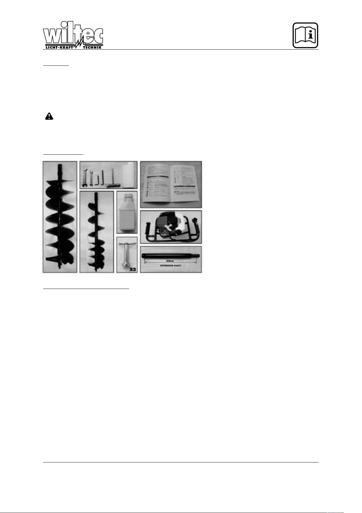
Packing list
1x HPHD52 Engine Assembly
1x 150mm Auger Bit
1x 200mm Auger Bit
1x 300mm Extension Shaft
3x Gudgeon Pins with Cotter pins
1x Spark Plug/Engine Tool
2x Spanners
2x Allen Keys
1x 76ml 2 Stroke Synthetic Oil
1x 50:1 Fuel Mixture Bottle
1x Operators Manual
Features / Specifications
KNOW YOUR POST HOLE DIGGER
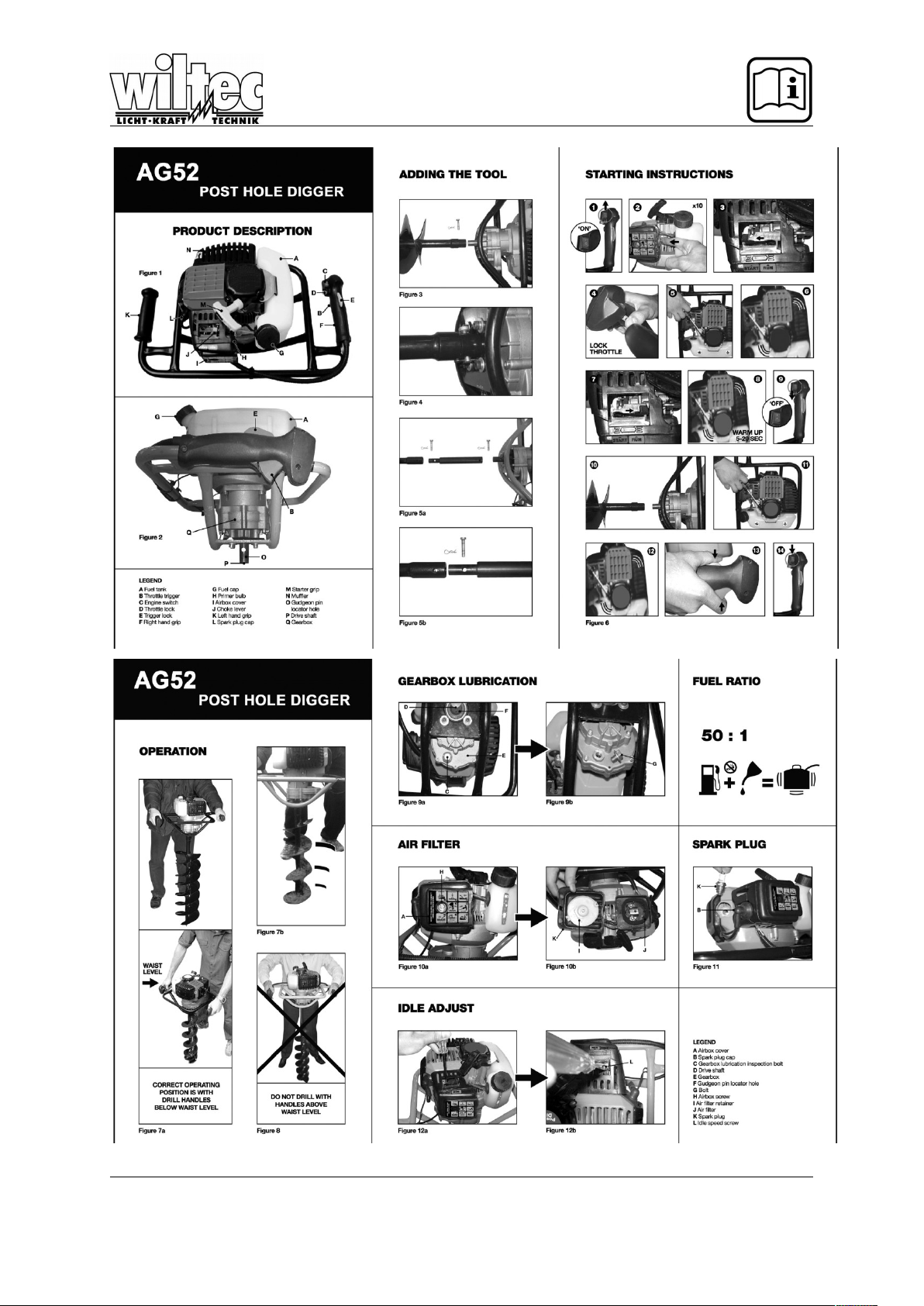
See Figure 1&2 (All figures are attached at the end of this manual)
The safe use of this product requires an understanding of the information on the product and in this
operator’s manual as well as knowledge of the project you are attempting. Before use of this project,
familiarize yourself with all operating features and safety rules.
AIRBOX
The airbox cover houses the air filter which helps to limit the amount of dirt and dust drawn into the
unit during operation.
CHOKE LEVER
The choke lever is used when starting the engine.
DRIVESHAFT
The driveshaft is connected to attachments to transfer movement.
ENGINE SWITCH
The engine switch is used in combination with the recoil starter grip to start the engine. It is also used
to turn the engine off.
© by WilTec Wildanger Technik GmbH Seite 31
http://www.WilTec.de
http://www.aoyue.eu
http://www.teichtip.de
Page 10

FUEL TANK
950ml
GEARBOX
The gearbox transfers the engines RPM to a slower high torque output.
GUDGEON PIN LOCATOR HOLE
The gudgeon pins secure the attachments to the driveshaft via the locator holes.
PRIMER BULB
The primer bulb is used to prime the carburetor prior to cold starting or if the unit has not been used for
a while.
RECOIL STARTER GRIP
The recoil starter grip is used (along with the engine switch) to start the engine.
THROTTLE LOCK
The throttle lock is used to help the engine on cold starts.
THROTTLE TRIGGER
The throttle trigger helps the operator control the speed of the auger to suit various ground conditions.
TRIGGER LOCK
The trigger lock prevents the operator from accidently activating the throttle trigger. The trigger lock
must be depressed before applying the throttle.
Specifications
Model : 61197
Type : Air cooled 2-stroke engine
Total Displacement : 51,7 CC
Fuel Mix Ratio : 50:1
Power : 1.46 kw/6500rpm
Gearbox Reduction Ratio : 40:1
Auger Speed : 200-230rpm
Idle Speed : 2800+-200rpm
Clutch Engagement Speed : 3900+-200rpm
Maximum Engine Speed : 8800+-200rpm
Ignition : Transistor magneto CDI
Weight : 9.8 KG
Fuel Tank Volume : 0.98 L
Auger Diameter : 150mm, 200mm
Extension Shaft : 300mm
© by WilTec Wildanger Technik GmbH Seite 32
http://www.WilTec.de
http://www.aoyue.eu
http://www.teichtip.de
Page 11

Assembly
Unpacking
Carefully remove the tool and any accessories from the box. Make sure that all items listed in the
packing list are included.
Inspect the tool carefully to make sure no breakage or damage occurred during shipping.
Do not discard the packing material until you have carefully inspected and satisfactorily operated
the tool.
WARNING!
If any parts are missing do not operate this tool until the missing parts are replaced. Failure to
do so could result in possible serious injury.
WARNING!
Do not attempt to modify this tool or create accessories not recommended for use with this
tool. Any such action or modification is misuse and could result in a hazardous condition leading to possible serious personal injury.
Fitting the Auger Bits
See figure 3&4
Align the engine drive shaft into the seat on the auger bit and secure it using the appropriate gudgeon
pin and cotter pin.
NOTE: Your post hole digger is supplied with a 300mm extension shaft to be used for deeper
hole digging. DO NOT start digging a hole with the extension attached.
The hole should always be started with the ager bit only fitted. Once the hole is deep enough and the
operator handles are at least 300mm below waist level, you may stop the unit and attach the extension
shaft between power head and the auger (see figure 5a-5b) for added comfort and deeper holes.
WARNING!
Never use the drill with the handles above waist level (see figure 8). Drilling with the unit’s
handles above waist level restricts control and can cause serious chest injuries if a hard object
is struck.
WARNING!
Do not change the ratio of the reduction gearbox. The characteristics of the machine could
change and unforeseen reactions could occur.
© by WilTec Wildanger Technik GmbH Seite 33
http://www.WilTec.de
http://www.aoyue.eu
http://www.teichtip.de
Page 12

Working Rules
WARNING!
Always follow the safety rules. The post hole digger must only be used to drill ground. Do not
lock the power drill onto fixed supports. It is forbidden to apply tools or applications other than
the ones indicated and approved by the manufacturer.
OPERATION
WARNING!
Do not allow familiarity with tools to make you careless. Remember that a careless fraction of
a second is sufficient to inflict serious injury.
EAR PROTECTION
WARNING!
Always wear safety goggles of safety glasses with side shields when operating this tool. Failure to do so could result in objects being thrown into your eyes resulting in personal injury.
WARNING!
Do not use any attachments or accessories not recommended by the manufacturer or this
tool. The use of attachments or accessories not recommended can result in personal injury.
NOTE: Read the operators manual and follow warnings and safety instructions.
NOTE: Keep all bystanders, especially children and pets, at least 3m from the
operating area.
FUEL AND REFUELING SAFETY
Always handle fuel with care, it is highly flammable.
Always refuel outdoors where there are no sparks and flames. Do not inhale fuel vapours.
Do not let petrol and oil come in contact with your skin.
Keep petrol and oil away from eyes. If petrol or oil comes in contact with eyes, wash them immedi-
ately with clean water. If irritation is still present, see a doctor immediately.
Clean up spilled petrol immediately.
MIXING THE FUEL
This product is powered by a 2-stroke engine and requires pre-mixing of petrol and 2-stroke oil.
Mix unleaded petrol and 2-stroke engine oil in a clean container approved for petrol.
This engine is certified to operate on unleaded petrol intended for automotive use with an octane
rating of 90 ([R+M]/2) or higher.
Do not use Ethanol fuels containing Ethanol. The use of Ethanol fuels may void your warranty.
Do not use any type of pre-mixed petrol/oil intended for use in mopeds, motorcycles, etc..
Use synthetic 2-stoke oil only. Do not use automotive oil or 2-stroke outboard oil.
© by WilTec Wildanger Technik GmbH Seite 34
http://www.WilTec.de
http://www.aoyue.eu
http://www.teichtip.de
Page 13
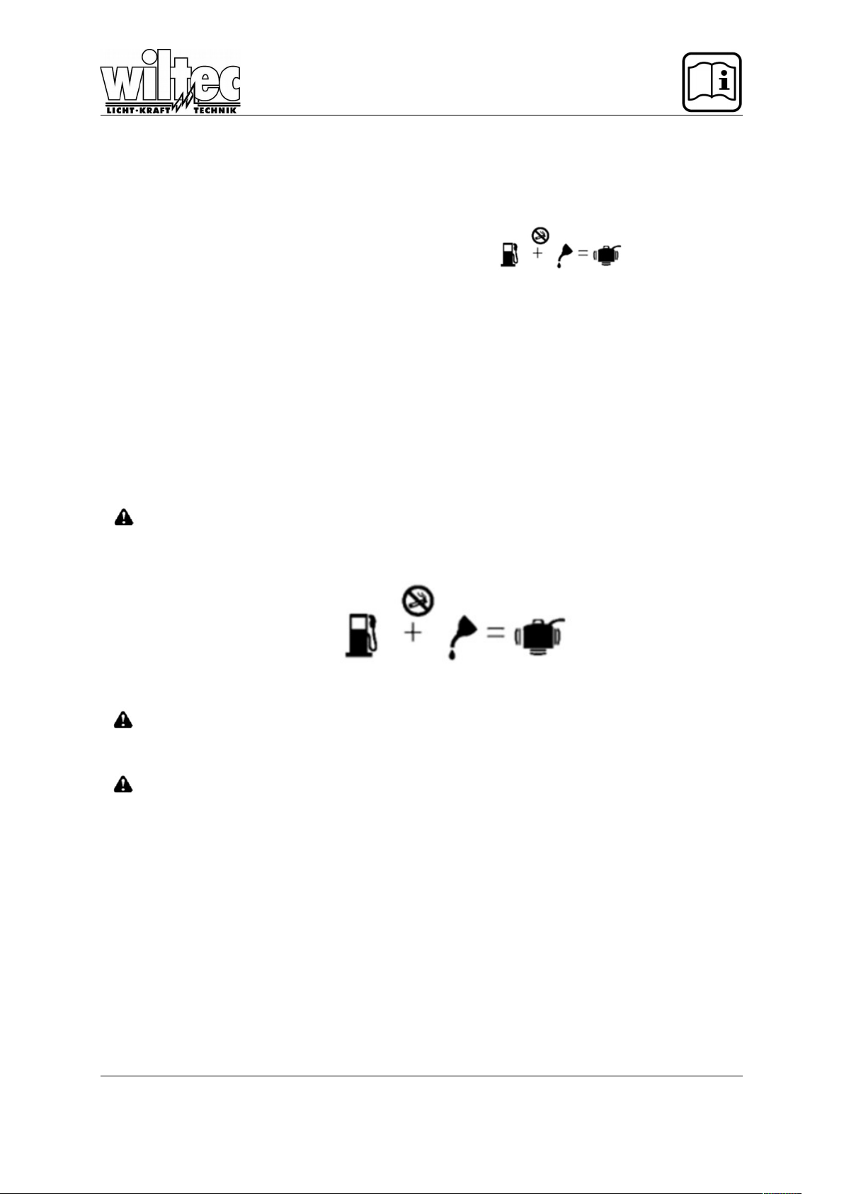
Mix 2% synthetic 2-stroke oil into the petrol. This is a 50:1 ratio.
Mix the fuel thoroughly and also each time before fueling.
Mix in small quantities. Do not mix quantities larger than usable in 30 day period. Synthetic 2-
stroke oil containing a fuel stabilizer is recommended.
FILLING THE TANK
Clean surface around fuel cap to prevent contamination.
Loosen fuel cap slowly to release pressure and to keep fuel from escaping around the cap.
Carefully pour fuel mixture into the tank. Avoid spillage.
Prior to replacing the fuel cap, clean and inspect the gasket.
Immediately replace fuel cap and tighten it hard.
Wipe up any fuel spillage. Move 9m away from refueling site before starting engine.
NOTE: It is normal for smoke to be emitted from a new engine during and after first use.
WARNING!
Always shut off engine before fueling. Never add fuel to a machine with a running or hot engine. Move at least 9m from refueling site before starting engine. Do not smoke!
Mixing ratio:
1 Litre + 20ml=
2 Litres + 40ml=
3 Litres + 60ml=
4 Litres + 80ml=
5 Litres +100ml=
STARTING AND STOPPING
WARNING!
Never start or run the engine inside a closed or purely ventilated area, breathing exhaust
fumes can kill.
WARNING!
Do not have the auger bit attached when starting a cold engine. The auger bit may rotate
when the engine starts with throttle lock engaged. Start the engine following the procedure below. Allow the engine to warm up. With the engine warmed up, you may stop the engine, fit the
auger bit and re-start the engine following the warm start procedure.
NOTE: Be sure to return the stop switch to the “I” position before trying to start the unit.
TO START A COLD ENGINE
See figure 6
Place the engine switch to the on position “I”.
PRIME-press the primer bulb 10 times slowly.
SET the choke lever to “START” position.
Lock on the throttle by pulling the throttle trigger and pressing in the lock button.
© by WilTec Wildanger Technik GmbH Seite 35
http://www.WilTec.de
http://www.aoyue.eu
http://www.teichtip.de
Page 14

PULL the starter rope with a quick firm and consistent upwards motion until the engine fires or
starts and runs.
If the engine fires (pops) but does not continue to run, move the choke lever back to the “RUN” po-
sition.
Allow the engine to warm up for 5-20 seconds.
TO START A WARM ENGINE
With the engine switch is on “I” position, PULL the starter rope with a quick firm and consistent upward
motion until the engine starts.
NOTE: Do not use the choke when starting a hot engine.
TO STOP THE ENGINE
Press the engine switch to the stop “O” position. Wait until the engine stops.
OPERATING THE POST HOLE DIGGER
See figure 7a-7b
Grip the power drill firmly with both hands and keep all parts of the body from the auger bit and
muffler.
Hold the post hole digger in front of you with the right hand firmly gripping on the throttle handle
and your left hand firmly gripping the other.
Always keep a firm grip with both hands while in operation.
The post hole digger should be held at a comfortable position with the handle height no higher
than waist level.
The throttle trigger helps control the speed of the auger to suit carious ground conditions.
Keep a comfortable distance between yourself and the drill without overreaching.
Always pay full attention to you operation. Serious injuries may result if contact is made with rotat-
ing auger.
Note: Your post hole digger is supplied with a 300mm extension shaft to be used for deeper
hole digging. Do not start digging a hole with the extension shaft attached.
© by WilTec Wildanger Technik GmbH Seite 36
http://www.WilTec.de
http://www.aoyue.eu
http://www.teichtip.de
Page 15

The hole should always be started with the auger bit only fitted! Once the hole is deep enough and the
operator handles are at least 300mm below waist level, you may stop then and attach the extension
shaft between the head and the auger for added comfort and deeper hole depth.
WARNING!
See figure 8
Never use the drill with the handles above waist level. Drilling the unit’s handles above waist
level restricts control and can cause serious chest injuries if a hard object is struck.
MAINTENANCE
WARNING!
Use only original manufacturer’s replacement parts, accessories and attachments. Failure to
do so can cause possible injury, poor performance and my void your warranty.
You may make adjustments and repairs described here. For any other repairs the post hole digger
must only be repaired by an authorized service agent.
Consequences of improper maintenance may include excess carbon deposits resulting in loss of
performance and discharge of black oily residue dripping from the muffler.
Make sure all guards, deflectors and handles are properly and securely attached to avoid the risk
of personal injury.
ENGINE
Clean the cylinder fins with compressed air or brush periodically. Dangerous overheating of the engine
may occur due to impurities on the cylinder.
REDUCTION GEARBOX
See figure 9a-9b
Change the grease in the reduction box every 100 working hours.
LUBRICANT FOR REDUCTION GEARBOX
The post hole digger is supplied with TAMOIL TAMLITH GREASE2 in the reduction gearbox. The lu-
brication within the gearbox should be checked periodically. To check the lubrication condition and
level remove the screw under the reduction gearbox.
CLEANING THE EXHAUST PORT AND THE MUFFLER
Depending on the type of fuel and oil and your operating conditions, the exhaust port and muffler may
become blocked with carbon deposits. If you notice a power loss with your petrol powered tool, a qual-
ified and authorized technician will need to remove these deposits to restore power.
© by WilTec Wildanger Technik GmbH Seite 37
http://www.WilTec.de
http://www.aoyue.eu
http://www.teichtip.de
Page 16

CLEANING AIR FILTER
See figure 10a-10b
A dirty air filter will cause starting difficulties, loss of performance and shorten the life span of the en-
gine. Check the air filter monthly. For best performance, replace the air filter at least once a year.
Loosen the air filter cover by turning the fixing screw counter clockwise.
Remove the airbox cover and air filter.
Clean the foam filter element with warm soap water. Rise and let it dry.
NOTE: If the foam filter is damaged, it should be replaced.
Apply a light coat of engine oil to the foam filter element and then squeeze it out.
Reinstall the air filter.
NOTE: Make sure the filter is seated properly inside the cover. Installing the filter incorrectly
will allow dirt to enter the engine causing rapid engine wear.
Reinstall the airbox cover and tighten the fixing screw to secure.
FUEL TANK
WARNING!
A leaking fuel cap is a fire hazard and must be replaced immediately.
The fuel cap contains a sealing gasket and a check valve to ventilate built up fuel gasses. A clogged
check valve will cause poor engine performance. If performance improves when the fuel cap is loos-
ened the check valve may be faulty. Replace fuel cap if required. The fuel supplied to the engine is
passed through a filter to remove any contaminants from entering the engine. Contaminants in the fuel
can cause poor performance and damage to the engine.
The fuel filter is a non-serviceable item and must only be replaced by an AUTHORISED SERVICE
CENTRE.
SPARK PLUG REPLACEMENT
See figure 11
This engine uses an NGK BPMR6A or Champion RCJ6Y spark plug with 0.50mm electrode gap. Use
an exact replacement and replace annually.
© by WilTec Wildanger Technik GmbH Seite 38
http://www.WilTec.de
http://www.aoyue.eu
http://www.teichtip.de
Page 17

IDLE SPEED REPLACEMENT
See figure 12a-12p
If the auger attachment turns at idle, the idle speed screw on the engine needs adjusting. Turn the idle
speed screw counter clockwise to reduce the idle RPM and stop the auger attachment movement. If
the auger attachment still moves at idle speed, contact a service point for adjustment and discontinue
use until the repair is made.
Clean all foreign material from the product. Store the idle unit indoors in a dry, well ventilated area
that is inaccessible to children. Keep away from corrosive agents such as garden chemicals.
Abide by all ISO and local regulations for the safe storage and handling of petrol.
WHEN STORING FOR 1 MONTH OR LONGER
Drain all fuel from the tank into a container approved for petrol. Run the engine until it stops.
© by WilTec Wildanger Technik GmbH Seite 39
http://www.WilTec.de
http://www.aoyue.eu
http://www.teichtip.de
Page 18

Troubleshooting
If these solutions do not solve the problem, please contact your authorized service dealer.
PROBLEM POSSIBLE
CAUSE
SOLUTION
Engine will not
start
No spark
No fuel
Engine is
flooded
Starter rope
pulls harder
now than
when new
Check Spark. Remove spark plug. Reattach the spark plug cap and
lay spark plug on metal cylinder. Pull the starter rope and watch for
spark at spark plug tip. If there is no spark, repeat the test with a new
spark plug.
Push primer bulb until bulb is full of fuel. If bulb does not fill, the pri-
mary fuel system is blocked. Contact a service dealer. If the primer
bulb fills, the engine might be flooded. Proceed with the next solution.
Set the choke lever to the START position. Squeeze the throttle trig-
ger and pull the starter rope repeatedly until the engine starts and
runs.
NOTE: Depending on the severity of the rope.
Contact an authorized service dealer.
Engine starts
but will not accelerate
Engine requires
approximately
three minutes to
warm up sufficiently
Allow engine to completely warm up. If engine does not accelerate after
three minutes, contact an authorized service dealer.
Engine starts
but will only
run at high
speed at half
choke
Carburetor requires adjustment.
Contact an authorized service dealer.
Engine does
not reach full
speed and
emits excessive smoke
Check oil fuel
mixture
Air filter is
dirty
Spark ar-
restor screen
is dirty
Use fresh fuel and the correct 2-stroke oil mix.
Clean air filter. Refer to cleaning the air filter earlier in this manual.
Contact an authorized service dealer.
Engine starts,
runs and accelerates but
will not go idle
Idle speed screw
on carburetor requires attachment.
Turn idle speed screw clockwise to increase idle speed.
The auger attachment
turns at idle
Idle speed is set
to high. Gearbox
clutch is inoperable.
Turn the idle speed screw counter clockwise to reduce the idle RPM and
stop the auger attachment. Contact an authorized service dealer for adjustment and discontinue use until the repair is made. Serious personal in-
jury might result from the auger attachment turning at idle.
Oil drips from
the muffler
Check oil/fuel
mixture.
Air filter is
dirty.
Use fresh fuel and the correct synthetic 2-stroke oil mix.
Clean following the instructions in the maintenance section.
Figures for Illustration
© by WilTec Wildanger Technik GmbH Seite 40
http://www.WilTec.de
http://www.aoyue.eu
http://www.teichtip.de
Page 19
© by WilTec Wildanger Technik GmbH Seite 41
http://www.WilTec.de
http://www.aoyue.eu
http://www.teichtip.de
Page 20
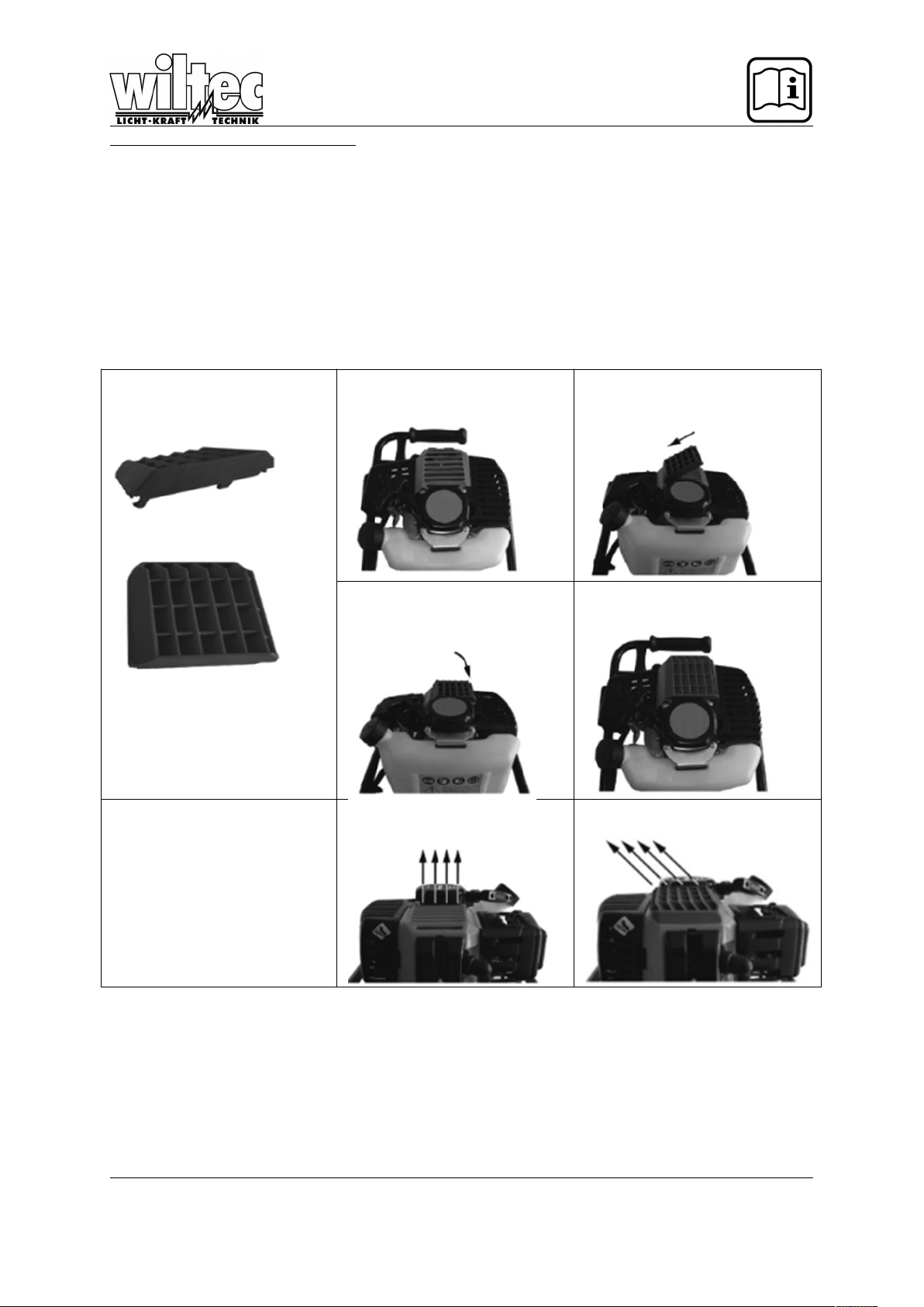
ENGINE HEAT DEFLECTOR
Thank you for buying an post hole digger!
For added comfort during warmer conditions you may choose to attach the supplied heat deflector
grill. The heat deflector grill is designed to direct the warm air flow away from the user during use in
warmer conditions. Please follow the instructions for correct mounting.
Note: Once the heat deflector is correctly fitted it cannot be removed.
Step 1
Please find the heat deflector grill
included in the accessory contents.
Step 2
Lay the engine assembly on a flat
surface as shown.
Step 3
Insert one end of the deflector grill as
per the arrow indicated.
Step 4
Hold down the inserted end and
push down the opposite end until
the grill clicks in position.
Step 5
Mounting is complete as shown.
Working principle
Cooling air direction without deflector grill fitted
Cooling air direction with deflector
grill fitted
© by WilTec Wildanger Technik GmbH Seite 42
http://www.WilTec.de
http://www.aoyue.eu
http://www.teichtip.de
Page 21
Disposal regulations
EU guidelines regarding the disposal of scrap electric appliances (WEEE, 2012/19/EU) were
implemented in the law related to electrical and electronic equipment and appliances.
All WilTec electric devices that fall under the WEEE regulations are labelled with the crossed-out
wheeled waste bin logo. This logo indicates that this electric equipment must not be disposed with the
domestic waste.
The company WilTec Technik GmbH has been registrated in the German registry EAR under the
WEEE-registration number DE45283704.
Disposal of used electrical and electronic appliances
(intended for use in the countries of the European
Union and other European countries with a separate
collection system for these appliances).
The logo on the article or on its packaging points out
that this article must not be treated as normal
household waste but must be disposed to a recycling
collection point for electronic and electrical waste
equipment. By contributing to the correct disposal of
this article you protect the environment and the health
of your fellow men. Environment and health are
threatened by inappropriate disposal.
Materials’ recycling helps reduce the consumption of raw materials.
Additional information on recycling this article can be provided by your local community, municipal
waste disposal facilities or the store where you purchased the article.
Address:
WilTec Wildanger Technik GmbH
Königsbenden 12 / 28
D-52249 Eschweiler
Important notice:
The reprint or reproduction, even of excerpts, and any commercial use, even in part of this instructions
manual require the written permission of WilTec Wildanger Technik GmbH.
© by WilTec Wildanger Technik GmbH Seite 43
http://www.WilTec.de
http://www.aoyue.eu
http://www.teichtip.de
 Loading...