

Page 1
Operation Manual
ARTICEL 51745
Read and follow the operating instructions and safety information before using for the first time.
Technical changes reserved!
Due to further developments, illustrations, functioning steps and technical data can differ
insignificantly.
Updating the documentation
If you have suggestions for improvement or have found any irregularities please contact us.
© by WilTec Wildanger Technik GmbH Seite 1
http://www.WilTec.de
http://www.aoyue.eu Version 5.2017
http://www.teichtip.de
Page 2

The information contained in this document is subject to change without prior notice. No part of this
document can be copied or duplicated in another form without the prior written consent of WilTec
Wildanger Technik GmbH. The WilTec Wildanger Technik GmbH assumes no liability for any errors in
this user manual or the connection diagram.
Although WilTec Wildanger Technik GmbH has made every effort to make sure that this user manual is
complete, accurate and updated, errors cannot always be avoided. In the event of problems with this
user manual please complete and send this form back to us.
FAX-notification (+++49 2403 55592-15),
from: ________________________________________
Name: ________________
Firm:_____________________
Tel/Fax:__________________
I would like to report the following mistakes:
_______________________________ ____________________________________
Customer Service WilTec Wildanger Technik GmbH
e-mail: [email protected]
Tel:++ +49 2403 55592-0
introduction
Thank you for purchasing this quality product. In order to minimize the risk of injury, we ask you to always take some basic safety precautions when using this device. Please read this manual carefully
and make sure you understand them.
The interior of this unit does not contain any user-serviceable parts. Leave maintenance, adjustment
and repair qualified personnel. In the case of a foreign intervention, the 2-year warranty period expires!
Keep these operating instructions in a safe place.
© by WilTec Wildanger Technik GmbH Seite 2
http://www.WilTec.de
http://www.aoyue.eu Version 5.2017
http://www.teichtip.de
Page 3

Description
The motor carrier, loadable up to a weight of 900 kg provides an ideal help for working on engines or
transmissions. A large variety of adjustments and adaption possibilities guarantee a high degree of
flexibility and security. While working turn the engine about 360° in order to get access even to those
areas that are difficult to reach. The four installation points can be easily adjusted with regard to angle
and distance and thus allow a universal adjustment for any engine. There are four steel rollers that ensure a safe position anf for an easy drivability of the entire construction.
Safety instructions / warnings
The owner and / or user must have read and understood the operating instructions of the device before using it. Installed personnel should be cautious, competent, trained and qualified in the safe handling of the working equipment used when working on engines and their components. Warnings
should be read and understood.
1. Be familiar with the application control, the application process and the warnings.
2. The engine stand may only be used for the removal and installation of engine stand es.
(Gears, differential gears, etc.)
3. Ensure that all connectors are secure and secure.
4. Make sure you know the contents of the instructions for use.
5. his device is not intended to be used by persons (or even children) with reduced physical,
sensory or mental abilities or persons who do not have the appropriate experience or knowledge, unless they are responsible for their safety Person or have previously been instructed
to use the equipment.
6. Children must be supervised to ensure that they do not play with the appliance.
7. Ensure that the load is free and no obstacles prevent / prevent the increase.
8. The engine stand may only be pushed slowly over level ground with load when fully lowered.
9. Ensure that the load can not slip or slip.
10. Check the loading balance after a few centimeters before proceeding further.
11. Avoid fluctuating the charge.
12. Ensure that no one is near the cargo.
13. Warn the present persons before lifting the charge.
14. Immediately report to your supervisor or workshop as soon as something unforeseen happens
15. Never lift more than maximum allowed
16. Never use damaged non-functioning engine stand .
17. Never use bent, damaged or worn load-bearing devices.
18. Never lift the load if an obstacle could interfere with the lift.
19. Stay concentrated and do not allow any distraction during the process.
20. Never use the load receptacle to lift, help or transport people.
21. NEVER SAVE LOADS ON PERSONS!
22. Unsecured loads can result in injuries to limbs or bones, including fatal injuries.
23. Avoid contact between the engine stand and other objects.
24. Never attempt to extend or repair the load receptacle
25. Do not use welding equipment near the support.
26. Always pay attention to the optimal lighting of the workplace.
27. Be sure to wear solid footwear.
28. Use a hairnet for long hair
29. Wear tight clothing.
30. Place jewelry (rings, earrings, watches, etc.)
© by WilTec Wildanger Technik GmbH Seite 3
http://www.WilTec.de
http://www.aoyue.eu Version 5.2017
http://www.teichtip.de
Page 4
31. Be careful not to wear loose straps or belts.
32. Only use the engine stand if you feel physically capable of doing so.
33. Long working in a standing position can lead to dizziness. Make regular breaks and drink
enough.
34. Only use the engine stand on straight and solid ground that can carry the specified loads.
35. Before beginning work on / under a vehicle, ensure that the vehicle is properly raised and secured.
36. Never open the screw connections under pressure / load.
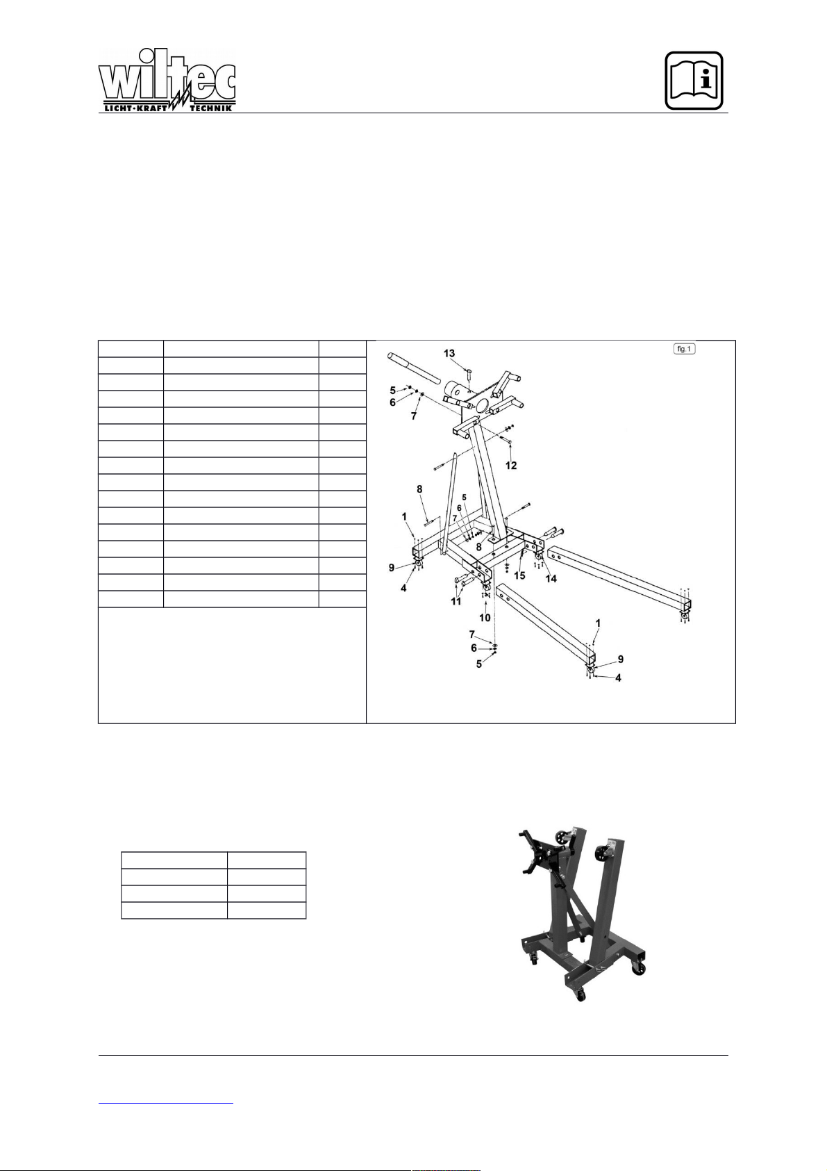
Parts list
P/N DESCRIPTION QTY
1 M8 Nut 16
4 M8x20 Bolt 16
5 M14 Nut 9
6 M14 Lock Washer 9
7 M14 Washer 9
8 M14x100 Bolt 5
9 Large Castor 4
10 M8x100 Bolt 8
11 Pin 16x110 4
12 M14x60 Bolt 4
13 Locking Pin 1
14 Small Castor 2
15 „R“ Clip 4
Specification
Max. capacity 900kg
Width 820mm
Length 1105mm
Height 910mm
© by WilTec Wildanger Technik GmbH Seite 4
http://www.WilTec.de
http://www.aoyue.eu Version 5.2017
http://www.teichtip.de
Page 5

Assembly
1.) Bolt the large castor wheels (9) to the rear-most mountings on the main frame and to the legs
using M8x20 bolts (4), M8 washers (3), M8 lock washers (2) and M8 nuts (1). Bolt the small
castor wheels (14) to the forward mountings on the main frame using M8x14 bolts (10), M8
washers (3), M8 lock washers (2) and M8 nuts (1).
2.) Assemble the legs to the frame using the 16x110 pins (11). Lay each leg into the open
channel and insert the first pin into the hole nearest the rear of the frame. This will be the
foldering leg pivot. Retain the pin with a “R” clip (15). Lock the leg in the down position by inserting a second 16x110 pin (11) into the hole nearest the open end of the channel and retain
with a “R” clip (15).
3.) Bolt the main upright to the cross member between the open channel using two
M14x100mm bolts (8), M14 washers (7), M14 lock washers (6) and M14 nuts (5). Do not fully
tighten the nuts at this stage.
4.) Take the two support struts and loosely bolt them to the top of the main upright using a
M14x100 bolt (8). Insert two M14 bolts (8) through the angled parts of the main base in the
holes adjacent to the rear square section ensuring that the bolt heads are on the outside of the
frame. Slide the bottom of each support strut over the end of each bolt in turn and secure with
the nuts and washers provided. Fully tighten all the nuts and bolts holding the main upright
and stuts.
5.) Take the engine mounting plate and insert it through the tube at the top of the main
upright. Rotate the plate until one of the holes in the inner tube is aligned with a hole in the
outer tube and insert the locking pin (13).
6.) Take the handle and insert it into the hole in the part of turning plate tube protruding
through the top of the main upright.
7.) Attach the adjustable mountings to the turning plate using M14x60 bolts (12), M14
washers (7), M14 lock washers (6) and M14 nuts (5).
8.) To fold up the legs remove the “R” clips (15) from the 16x110 pins (11) furthest from
the rear of the frame and pull out the pins. Fold the legs up. Always retain the legs in the upright position by re-inserting the pins (11) through the holes in the frame directly in front of the
folded legs. Retain the pins (11) with the “R” clips (15).
© by WilTec Wildanger Technik GmbH Seite 5
http://www.WilTec.de
http://www.aoyue.eu Version 5.2017
http://www.teichtip.de
 Loading...