

Wilson Manifolds 810100 User Manual

Installation Instructions for Pro-Flow Part. No.
810100 Progressive Nitrous Controller and
CAUTION: CAREFULLY READ INSTRUCTIONS BEFORE PROCEEDING
NOT LEGAL FOR USE OR SALE ON POLLUTION CONTROLLED VEHICLES.
Vehicle Data Logger
OVERVIEW
Pro-Flow Part. No. 810110 is a combination
progressive nitrous controller and vehicle data logger
with the following features:
• Controls two nitrous stages and purge solenoid. 40
amp output drive capability on each nitrous stage.
• Each stage is independently programmable based
on throttle position, RPM, vehicle speed, time
delay, and first gear lockout. Progressive control
based on RPM or time.
• Programmable automatic purge when system is
armed.
• Flexible RPM input compatible with high level coil
drive (vehicles with coil packs or distributor
ignition), standard 12V tach signal, or low level
logic drive (newer vehicles with coil-on-plug).
• General purpose input/output (GPIO) terminal.
Programmable for use as shift light output,
additional stage enable input, or control output for
ignition retard.
• Status LED output (ideal for use with arming switch
containing LED).
• Built-in data logging. Ideal as basic vehicle data
logger during dyno tuning or drag racing. Logs
data whenever system is armed. Stores last 5
minutes of data at 10 samples/second.
• Data logged includes throttle position, RPM,
vehicle speed, status of all inputs and outputs, and
two 0-5V analog inputs.
• 0-5V analog inputs are compatible with Daytona
Sensors dual channel WEGO III systems for
logging wide-band air/fuel ratio data.
• Heavy duty industrial grade clamping terminal
blocks allow easy and reliable hookup without
soldering or crimping.
• Compact size: is 4.1”L x 2.8”W x 1.1”H (not
including mounting feet and terminal block).
• USB interface to laptop PC. Powerful Windows
software for programming controller and
downloading logged data.
Nitrous Pro-Flow, 4700 NE 11
(954) 771-6216 www.nitrousproflow.com
th
St., Ft. Lauderdale, FL 33334 Pro-Flow Part. No. 810100
1/2008
Page 1
Figure 1 – Progressive Nitrous Controller
ADDITIONAL REQUIRED PARTS
The nitrous controller comes with a USB cable
and software on CDROM. To complete the installation,
you will require: wire, wire labels, crimp terminals,
fuses, switches, and relays. If you are adding the
controller to an existing nitrous system installation, you
may already have most of these items but some
rewiring may be required. The Appendix includes a list
of recommended parts and suppliers.
Throttle position sensor (TPS), RPM, and
vehicle speed sensor (VSS) signal connections are
required to utilize all the capabilities of the nitrous
controller. You will require a vehicle wiring diagram
to locate these signal connections.
INSTALLATION
1. Turn off the ignition switch and disconnect the
battery ground cable before proceeding.
2. Select a convenient mounting location for the
nitrous controller. The unit is not sealed and must
be mounted in a dry location away from sources of
heat. We recommend underdash mounting. The
unit is not intended for underhood mounting. You
can secure the controller with two sheet metal
screws or Velcro tape strips. Orient the unit so that
you will have easy access to the terminal blocks
and USB port.
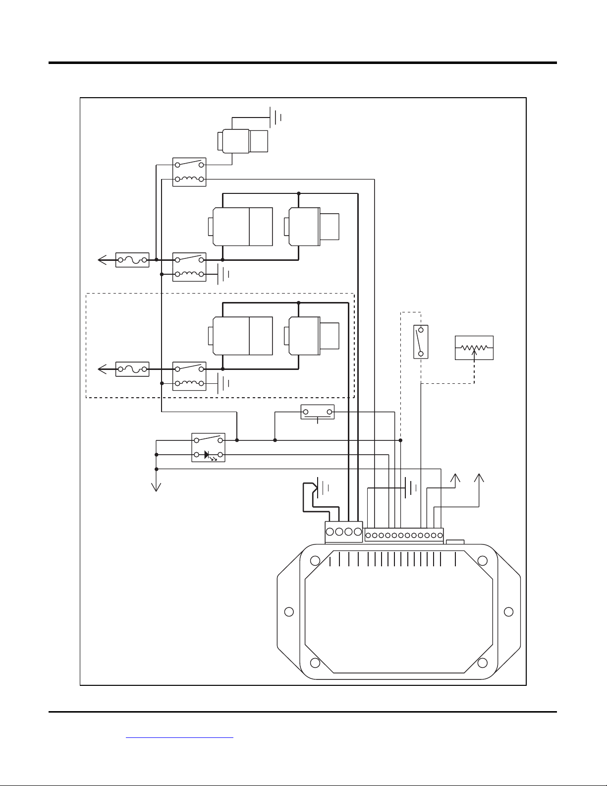
Figure 2 – Basic Hookup
GROUND
PURGE
SOLENOID
PURGE
RELAY
30
87
BATTERY+
STAGE 2
(OPTIONAL)
BATTERY+
50 AMP
MAXI FUSE
50 AMP
MAXI FUSE
STAGE 1
85
30
85
30
85
STAGE 1
STAGE 2
1
3
86
NITROUS
RELAY
87
86
GROUND
NITROUS
87
86
SOLENOID
GROUND
RELAY
1A
SOLENOID
MANUAL
FUEL
SOLENOID
FUEL
SOLENOID
PURGE
WIDE OPEN THROTTLE SWITCH
(NOT RECOMMENDED)
THROTTLE POSITION SENSOR
(RECOMMENDED)
4
VEHICLE SPEED SENSOR
(SEE NOTES)
SIGNAL (SEE NOTES)
RPM SIGNAL
ARMING SWITCH
WITH STATUS LED
(SEE NOTES)
TO SWITCHED AND
FUSED +12V POWER
Nitrous Pro-Flow, 4700 NE 11
th
St., Ft. Lauderdale, FL 33334 Pro-Flow Part. No. 810100
(954) 771-6216 www.nitrousproflow.com
GROUND
GROUND
TPS
VSS
RPM
ARM
GPIO
STAGE 1
STAGE 2
GROUND
PURGE IN
ANALOG 1
POWER GROUND
POWER GROUND
PURGE SOL
STATUS LED
ANALOG 2
+12V POWER
USB PORT
1/2008
Page 2

Figure 3 – Hookup for Independent Control of Nitrous and Fuel Flow
GROUND
PURGE
SOLENOID
PURGE
RELAY
30
87
BATTERY+
50 AMP
MAXI FUSE
85
30
85
86
FUEL
STAGE
RELAY
87
86
SOLENOID
WIDE OPEN THROTTLE SWITCH
(NOT RECOMMENDED)
THROTTLE POSITION SENSOR
(RECOMMENDED)
GROUND
NITROUS
SOLENOID
1
3
1A
4
MANUAL
PURGE
VEHICLE SPEED SENSOR
(SEE NOTES)
SIGNAL (SEE NOTES)
RPM SIGNAL
ARMING SWITCH
WITH STATUS LED
(SEE NOTES)
TO SWITCHED AND
FUSED +12V POWER
Nitrous Pro-Flow, 4700 NE 11
th
St., Ft. Lauderdale, FL 33334 Pro-Flow Part. No. 810100
(954) 771-6216 www.nitrousproflow.com
GROUND
GROUND
TPS
VSS
RPM
ARM
GPIO
STAGE 1
STAGE 2
GROUND
PURGE IN
ANALOG 1
POWER GROUND
POWER GROUND
PURGE SOL
STATUS LED
ANALOG 2
+12V POWER
USB PORT
1/2008
Page 3

3. Refer to Figure 2 for basic hookup. Figure 3 shows
hookup for a system with independent control of
nitrous and fuel flow (refer to page 16 for details).
All signal and low current connections (thin lines)
can be made with 18-20 AWG wire. High current
connections (thick lines) require 14 AWG wire.
4. Working with clamping terminal blocks. All
connections to the controller terminal blocks must
be clearly identified either by means of distinct wire
colors or the use of wire labels. If you use distinct
wires colors, mark up Figure 2 or 3 for future
reference. Refer to the Appendix for recommended
wire labels. Wire should be stripped back 3/16-1/4
inch. No bare wire should be visible outside the
terminal block. Use a miniature Phillips or flat
screwdriver to tighten the screws.
5. Solenoid connections. Relays with a minimum 40
amp rating are required. If your nitrous system
uses large solenoid valves, you should use the
heavy duty P&B/Tyco VF7 series 70 amp relays
listed in the Appendix. The use of 50 amp fuse
blocks such as the Littlefuse Maxi Fuse series
listed in the Appendix is recommended. Power
connections from the fuse blocks must go direct to
the battery positive terminal. The ground
connection from the solenoids must go to a chassis
ground stud or may be connected direct to the
battery negative terminal. Use 14 AWG wire. Keep
power and ground connections as short as
possible.
6. Arming switch and status LED. The hookup
diagrams show terminal numbers for the
recommended C&K DM series illuminated power
rocker switch (refer to the Appendix for details).
You can also use a separate switch and LED. The
controller has an internal 1K ohm current limiting
resistor on the status LED output and can directly
drive any LED. The status LED output cannot drive
a conventional lamp. Most vehicles will have an
accessory fuse that can be used as a source for
the switched and fused +12V power connection.
Refer to the Appendix for recommended fuse taps.
7. Manual purge switch. If you require manual purge
capability, connect a momentary switch as shown.
Refer to the Appendix for the recommended C&K
DM series rocker switch.
8. Throttle position sensor (TPS) signal. Most
vehicles manufactured since 1981 will have a TPS
with 0-5V output located on the throttle body or
carburetor. Refer to the vehicle wiring diagram for
details. You can check the TPS signal with a DVM.
Some late model vehicles with drive-by-wire
electronic throttle bodies will have a dual output
accelerator pedal sensor. The signal voltage on
one output will rise with increasing pedal position
and the other output will drop. Connect the nitrous
controller TPS input to the rising signal. Solder this
signal connection and wrap with self vulcanizing
electrical tape (refer to the Appendix). If a suitable
0-5V signal is not available, you can use a wide
open throttle switch as shown in Figures 2 or 3.
9. RPM signal. This connection is required to utilize
the full capabilities of the controller. Depending on
your vehicle type and engine control, there are
three possible sources for the RPM signal:
a. High level signal on the Coil- terminal of
most inductive discharge type
ignitions. This includes most original
equipment (OE) ignitions except coil-onplug with integrated drive electronics. For
distributorless systems with multiple coil s
or coil packs, you can use any one of the
Coil- signals. Refer to the vehicle wiring
diagram for details. The Coil- terminal will
connect to an ignition module or engine
control module (ECM). The Coil+ terminal
will connect to switched +12V.
b. Tach signal (preferred for best noise
immunity). The controller is compatible
with industry standard 12V square wave
tach signals such as what would be used
to drive an Autometer or similar
aftermarket tach. Most aftermarket
capacitive discharge (CD) ignitions
including the MSD-6 and Crane HI-6 series
have a tach output that you can use.
c. Low level logic signal. This type of signal
is found on late model vehicles, including
many imports, that use coil-on-plug with
integrated drive electronics. Refer to the
vehicle wiring diagram for details. You can
use the signal that goes from the ECM to
any one of the coil-on-plug units.
Unless you are using the tach terminal on an
aftermarket ignition or a screw terminal on a coil,
you should solder the RPM signal connection and
wrap with self vulcanizing electrical tape (refer to
the Appendix). During initial setup, you must
configure an RPM signal level jumper inside the
nitrous controller. Refer to the Initial Setup section
on page 15 for details.
Nitrous Pro-Flow, 4700 NE 11
th
St., Ft. Lauderdale, FL 33334 Pro-Flow Part. No. 810100
(954) 771-6216 www.nitrousproflow.com
1/2008
Page 4
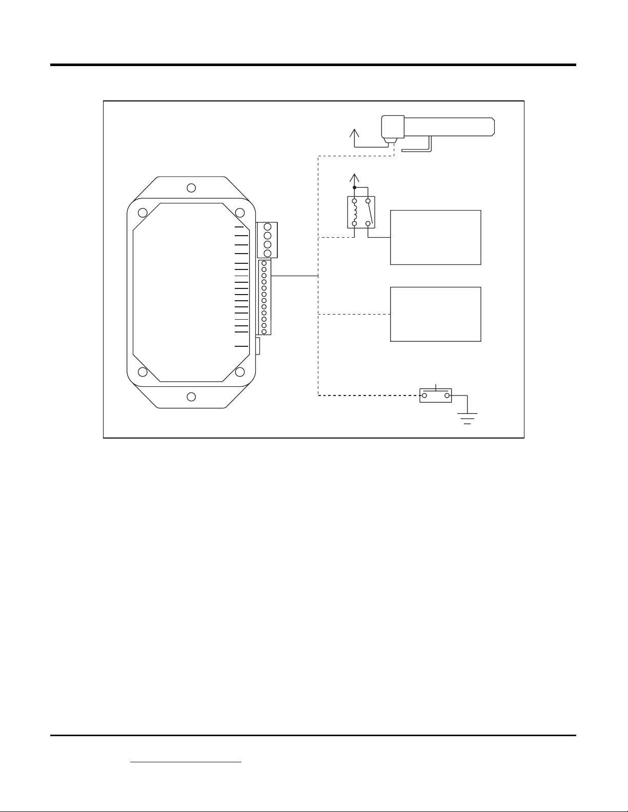
Figure 4 – GPIO Hookup Options
POWER GROUND
POWER GROUND
STAGE 2
STAGE 1
GROUND
PURGE SOL
GPIO
STATUS LED
PURGE IN
ARM
ANALOG 2
ANALOG 1
RPM
+12V POWER
USB PORT
TPS
VSS
SWITCHED +12V
SWITCHED +12V
85
RETARD
RELAY
86
LED SHIFT LIGHT
(AUTOMETER 5330)
+
-
30
IGNITION SYSTEM
87
WITH ACTIVE HIGH
RETARD
RETARD INPUT
INPUT
SUCH AS MSD OR
ACCEL
IGNITION SYSTEM
WITH ACTIVE LOW
RETARD
RETARD INPUT
INPUT
SUCH AS CRANE
HI-6
ADDITIONAL TRIGGER SWITCH
10. Vehicle speed sensor (VSS) signal. This
connection is required to utilize the full
capabilities of the nitrous controller. Most
vehicles manufactured since 1981 will have a
VSS. Refer to the vehicle wiring diagram for
details. Some late model vehicles with anti-skid
braking (ABS) and electronic stability control
(ECS) systems utilize individual wheel sensors
use to calculate an average vehicle speed.
Accessing a discrete vehicle speed signal on
these systems may not be possible. You may
have to install a driveshaft sensor (contact tech
support for details). For Nissan 350Z
applications, you can access vehicle speed on
the 8P/R signal (pin 26 on the unified meter and
A/C amp module behind the center console).
11. Optional general purpose input/output (GPIO)
signal. Refer to Figure 4 for GPIO hookup
options. If you use the GPIO to drive a shift light,
you must use an 12V LED type. The GPIO
cannot drive a conventional lamp. If you use the
GPIO to retard an aftermarket ignition that
Nitrous Pro-Flow, 4700 NE 11
(954) 771-6216 www.nitrousproflow.com
th
St., Ft. Lauderdale, FL 33334 Pro-Flow Part. No. 810100
1/2008
requires a 12V (active high) signal, you must use
a relay as shown. Refer to the Appendix for
recommended relays.
12. Optional analog input signals. The nitrous
controller will log 0-5V data on two analog inputs.
Uses include logging air/fuel ratio from a wideband sensor system such as the Daytona
Sensors WEGO IIID shown in Figure 5. The
Nitrous Log software is used to set the units and
scaling for the analog inputs. Refer to the Nitrous
Log section for details.
13. Ground connections. Use 18 AWG wire for the
signal ground and two 14 AWG wires for the
power ground. Keep the ground connections as
short as possible. The ground connections must
go to a chassis ground stud (you can usually find
one under the dash). If you are using the analog
inputs, use the same ground point for any
associated devices in order to avoid signals
errors due to a ground loop.
14. Reconnect the battery ground cable.
Page 5
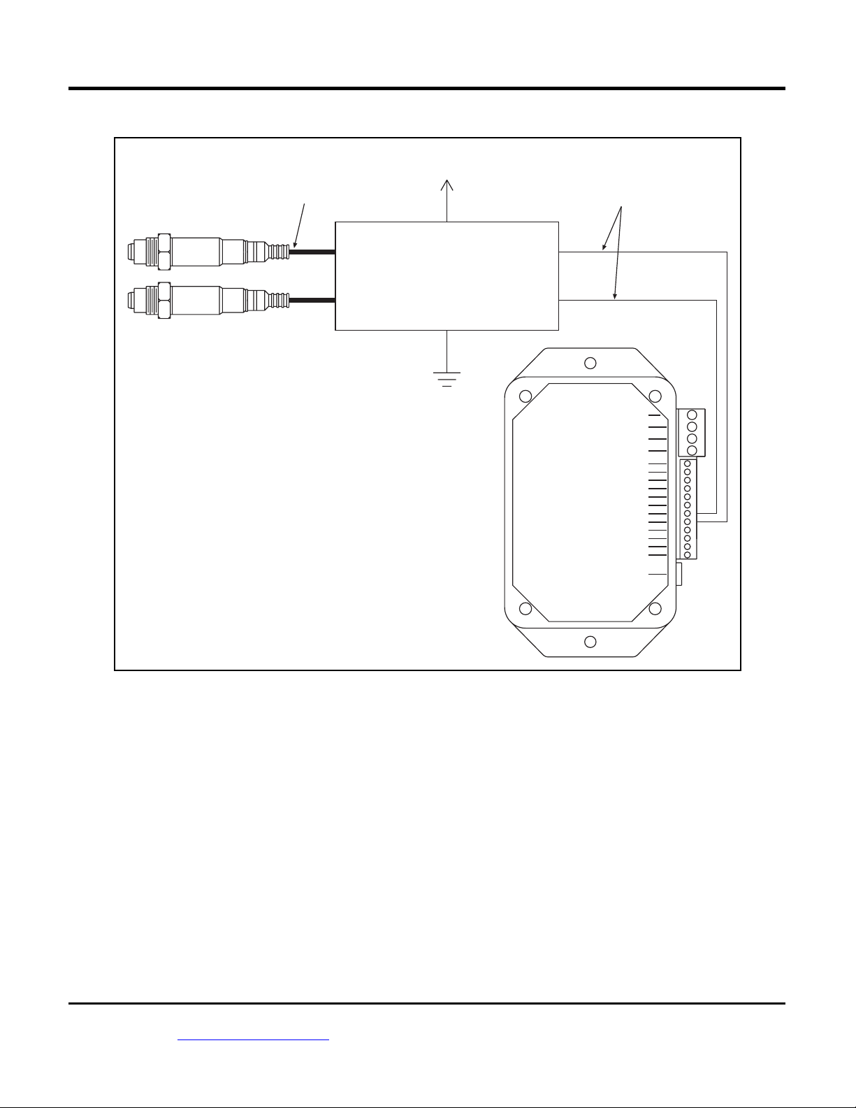
Figure 5 – Analog Input Hookup to Daytona Sensors WEGO IIID Wide-Band System
TO SWITCHED
SENSOR 1 CABLE
IDENTIFIED BY
YELLOW BAND
+12V POWER
RED
0-5V OUTPUT SCALED:
AFR = 10 + (2 x VOUT)
BOSCH
LSU 4.2
BOSCH
LSU 4.2
SENSOR 1 INPUT
WEGO IIID
SENSOR 2 INPUT
GROUND
SENSOR 1 AFR
OUTPUT
SENSOR 2 AFR
OUTPUT)
BLACK (2)
WHITE
BLUE
POWER GROUND
POWER GROUND
STAGE 2
STAGE 1
GROUND
PURGE SOL
GPIO
STATUS LED
PURGE IN
ARM
ANALOG 2
ANALOG 1
TPS
RPM
VSS
+12V POWER
USB PORT
OVERVIEW OF INITIAL SETUP
The nitrous controller requires initial setup to
establish nitrous system control parameters. PC Link
Nitrous software is used for setup. In addition, the
Nitrous Log data logging software is used to check for
proper scaling of the throttle position, RPM, and
vehicle speed inputs. Complete the software
installation and read the software sections of this
instruction manual, then continue the initial setup steps
on page 15.
PC REQUIREMENTS
The nitrous controller connects to your PC by
means of a USB interface. A USB cable is supplied
with the unit. The PC must have a free USB port. If you
have an older PC without USB capability, you cannot
use the controller.
Nitrous Pro-Flow, 4700 NE 11
(954) 771-6216 www.nitrousproflow.com
th
St., Ft. Lauderdale, FL 33334 Pro-Flow Part. No. 810100
1/2008
We recommend a laptop PC with Pentium
processor and super VGA display (SVGA with 1024 x
768 pixel resolution) running Windows 98/ME/XPVista.
Data chart display is graphics intensive and a high
speed Pentium processor is recommended.
Processors slower than 300 MHz will exhibit sluggish
program loading and response. The PC must have a
CDROM drive for program loading.
PC Link Nitrous and Nitrous Log software
include print commands to print downloaded data. The
programs have been tested with Hewlett-Packard laser
and inkjet printers and Epson inkjet printers. We
recommend using a color inkjet printer.
Page 6
 Loading...