

Wilson Manifolds 462259 5.9 User Manual

5.9 Dodge/Cummins Performance Kit
462259

2
Read Complete Instructions Before You Begin!!!
Please read these instructions carefully. This kit will eliminate the Grid Heater; the Grid
Heater Can Not be used with the Thrasher Elbow & Base Plate. To complete this installation,
the fuel system of your vehicle will be opened to the elements. Please exercise caution
whenever the fuel system is exposed to the elements. Try to keep your work area cleanand
free of contaminates such as dirt and sand which can damage your fuel injection system. Below
is a check list of steps to do before you begin your installation. Installation time should be about
two (2) hours for most persons with basic mechanical skills. Below is a checklist before you
begin:
Make sure your truck is parked on level ground with the emergency brake
engaged
Disconnect “Both” Negative Battery terminals
What is Included with this kit:
1. Wilson Manifolds Thrasher Cast Elbow
2. Wilson Billet Base Plate
3. Installation Hardware
The installation hardware included with this kit is as follows. Please check the item list and verify
that all your hardware has been shipped with your manifold:
1. One (1) Viton Manifold Gasket for Elbow
2. Two (2) 8mm x 1.25 x 55mm Studs
3. Two (2) 8mm x 1.25 12 point Nuts
4. Two (2) 8mm x 1.25 x 35mm Allen bolt (6mm head)
5. One (1) 8mm x 1.25 x 10mm Allen bolt (6mm head)
6. One (1) 8mm x 1.25 x 25mm Allen bolt (6mm head)
7. One (1) #2 Injection Line Bracket
The following is a list of tools you will need for the installation:
10mm deepsocket
10mm boxend wrench with 12pt end
11mmor 7/16” socket
8mm socket or box end wrench
3/8 ratchet
3” or 6” extension for 3/8 in ratchet
¾” or 19mm wrench
6mm allen key socket
T-15 torx bit or driver
Optional: Blue Loc-Tite
3
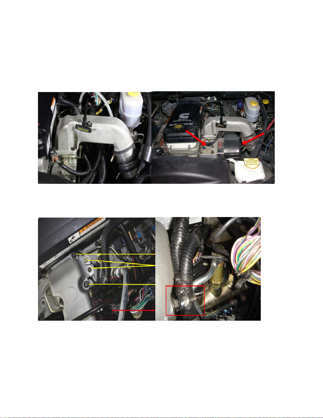
Here is what you will start out with.
Note: This truck is equipped with a dualfeed line. On trucks with a HPRV, instructions will vary.
On 2003-04 trucks withthe APPS sensor (indicated by the red arrow on the right), start by
removing the 3 bolts (indicated by the red arrow on left) that bolt the APPS to the head and let it
fall to the side. You do not need to disconnect any of the connections.
1) Remove the 10mm nylon lock nut that holds the injector (indicated by picture on right), fuel
rail pressure sensor, and map sensor wire harness as indicated by the red box below. Using the
10mm socket remove the back two intake bolts as well as the grid heater lead wires (indicated
in yellow).
4
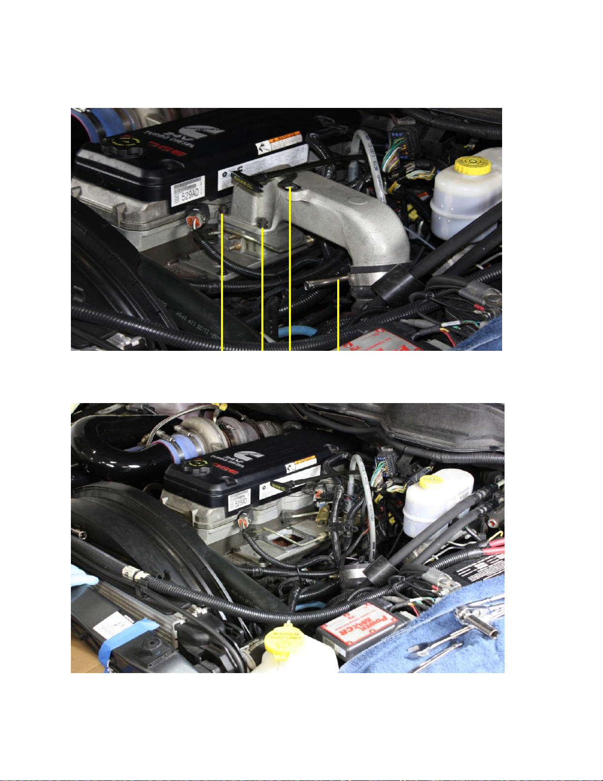
2) Loosen the t-bolt clamp bolt located where the intake horn and the intercooler discharge pipe
meet using the 11mm or 7/16” socket. Using the 10mm socket, remove the oil dipstick hold
down bolt followed by the front pair intake horn bolts (indicated in yellow)
3) Remove the intake horn and grid heater. On 2003-04 model year trucks, there will be a ground strap
bolt to the grid heater body and the factory base plate that will need to be removed. Use the 10mm
socket to remove the bolt from the base plate.
5
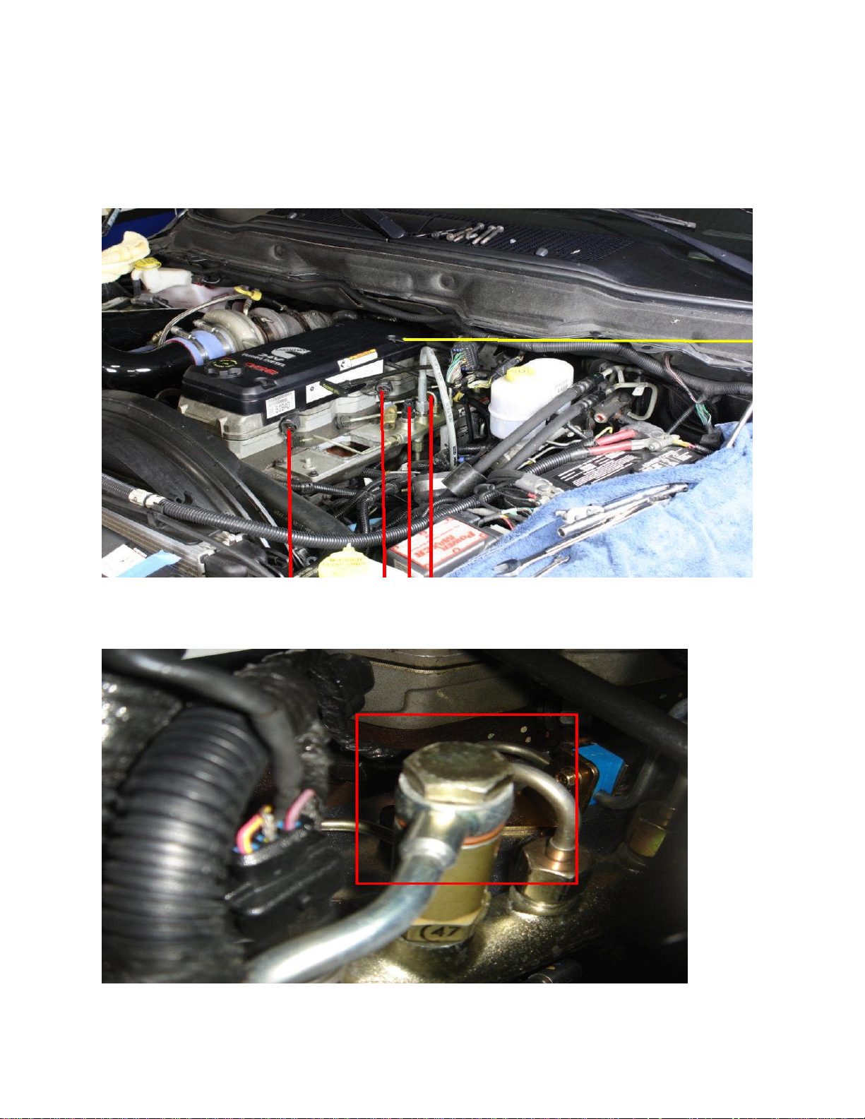
4) Remove the 10mm bolt holding the clamp for the rear injector harness (indicated in yellow).
Disconnect the front, middle and rear injector harness from the valve cover. Disconnect the rail
pressure and map sensor wiring harness and move it out of the way (indicated in red).
NOTE: On 2006 and 07 trucks, there are only two (2) connectors on the valve cover. These are
the injector harnesses that have been changed over in the 06 model year with the CAN system.
5) This truck is equipped with a dual feed line. For trucks with the High Pressure Relief Valve,
remove the banjo bolt using a 19MM or ¾” wrench (indicated by red box). Use caution not to
drop the sealing washers. Do not remove the HPRV from the rail, it is not necessary. The
HPRV is pictured below.
 Loading...