

Page 1

Signal Booster
Installation
Guide
Mobile Wireless
Single Band
Signal Booster
Contents:
How it Works ...................................1
Before Getting Started ............................2
Installing a Wilson Electronics Outside Antenna ........3
Installing a Wilson Electronics Signal Booster. . . . . . . . . . 4
Installing the Low-Profile Antenna ...................5
Powering Up a Wilson Electronics Signal Booster . . . . . . 6
Warnings and Recommendations ...................7
Understanding the Signal Booster Lights . . . . . . . . . . . . . 8
About Wilson Electronics ..........................9
Guarantee and Warranty .........................10
Signal Booster Specifications . . . . . . . . . . . . . .Back Cover
Wilson
®
Electronics, Inc.
Note: This manual contains important safety and operating information.
Please read and follow the instructions in this manual. Failure to do so
could be hazardous and result in damage to your signal booster.
Page 2

1
Contact Wilson Electronics Tech Support with any questions at 866-294-1660
Or email: [email protected] Hours: 7am to 6pm MST.
2
Installation Instructions for the Following Wilson Electronics Signal Boosters:
Mobile Wireless Single Band Cellular Signal Booster
Model #801101
FCC ID: PWO824WV IC: 4726A-824WV
Mobile Wireless Single Band iDEN Signal Booster
Model #804002
FCC ID: PWO806WV IC: 4726A-806WV
The term “IC” before the radio certification number only signifies that
Industry Canada technical specifications were met.
Inside this Package
How it Works
Your new Wilson Electronics signal booster has been carefully engineered to significantly
improve the performance of your cell phone or cellular data card in mobile applications.
Together with an outside antenna (sold separately), the signal booster’s state-of-the-art
technology is designed to increase your signal up to 10 times, reduce disconnects and
dropouts, and increase data communication rates needed for 3G technologies.
The outside antenna will collect the cell tower signal and send it through the cable to the
signal booster. The signal is then boosted and sent to the inside antenna. Your cell phone
or data card then communicates with the improved signal. When the cell phone or data card
transmits, the signal goes through the inside antenna, is boosted by the signal booster and
broadcast back to the cell tower through the outside antenna.
Wilson Electronics manufactures a wide variety of antennas to help you customize your
signal booster for your specific application. Several are shown below. See your dealer or
visit www.wilsonelectronics.com.
Wireless
Signal Booster
DC plug-in
power cable
NMO
Mount
301104
Magnet
Mount
301103
Trucker
Mount
301101
Mini
Magnet
301113
Marine
Antenna
301130
Low-profile
antenna
NOTE: Use of this signal booster
with an antenna gain higher than
5.12 dBi is in violation of FCC
regulations for which the
offender is fully liable. All
Wilson mobile antennas are
5.12 dBi or less in the 800
MHz band.
Page 3

2
Contact Wilson Electronics Tech Support with any questions at 866-294-1660
Or email: [email protected] Hours: 7am to 6pm MST.
Before Getting Started
This guide will help you properly install Wilson Electronics single-band, mobile wireless signal
booster. It is important to read through all of the installation steps for your particular
application prior to installing any equipment. Read through the instructions, visualize
where all the equipment will need to be installed and do a soft installation before mounting
any equipment. If you do not understand the instructions in full, seek professional help, or
contact Wilson Electronics Technical Support at 866-294-1660.
Warning: In a wireless installation, do not plug the signal booster directly
into the cell phone or data card using an
antenna adapter. It will damage the signal
booster.
!
Outside
Antenna
Inside
Antenna
Signal booster
DC Power
Supply
Cell Phone
PDA
Notebook
Installation Diagram
Page 4

3
Contact Wilson Electronics Tech Support with any questions at 866-294-1660
Or email: [email protected] Hours: 7am to 6pm MST.
4
Installing a Wilson Electronics Outside Antenna
To receive the best cell signal, select a location in the center of the vehicle’s roof at least
20 inches away from any other antennas and free of obstructions.
Follow the specific antenna installation instructions included with the outside antenna
(sold separately).
The outside antenna must be installed
vertically. Signal performance will be
degraded if the antenna is not vertical.
The antenna cable may run through the
door to the signal booster.
The antenna cable is small enough to easily
tuck under the door seal or plastic molding.
For a more professional-looking installation,
run the antenna cable under the door seal.
Carefully pull down the door seal. Run the
cable through the seal and push the seal
back into place. This prevents constant
wear and tear on the cable as the door
opens and closes.
Optional Magnet-
Mount Antenna
Shown
Part #301103
Carefully
Pull Down
Door Seal
Run Cable
Under
Seal
Tuck Cable
Under Seal
Warning:
Warning:
The outside antenna must be installed with a separation of at least 20 inches from any
of the vehicle’s occupants or nearby persons and must not be located or operating in
conjunction with any other antenna or signal booster.
Do not use any type of glass-mount antenna with this signal booster. The outside and
inside antennas must be shielded from each other to prevent oscillation.
Page 5
4
Contact Wilson Electronics Tech Support with any questions at 866-294-1660
Or email: [email protected] Hours: 7am to 6pm MST.
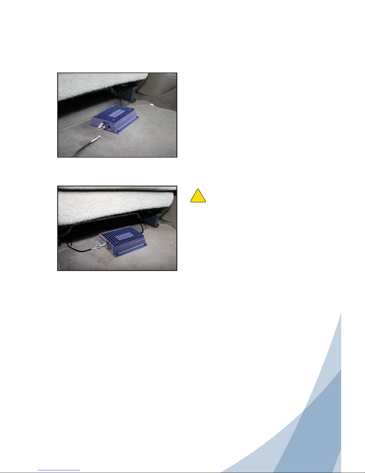
Installing a Wilson Electronics Signal Booster
Warning: Do not plug in the DC power
supply until the outside and inside antenna
cables are attached to the signal booster.
!
Select a location to install the signal booster
that is away from excessive heat, direct
sunlight or moisture and that has proper
ventilation.
Recommended installation locations are:
• Under the seat
• Under the dash
Run the cable from the outside antenna and
attach it to the FME-Male connector labeled
“outside antenna” on the signal booster.
Attach the inside antenna cable to the FMEMale connector labeled “inside antenna” on
the signal booster.
Page 6
5
Contact Wilson Electronics Tech Support with any questions at 866-294-1660
Or email: [email protected] Hours: 7am to 6pm MST.
6
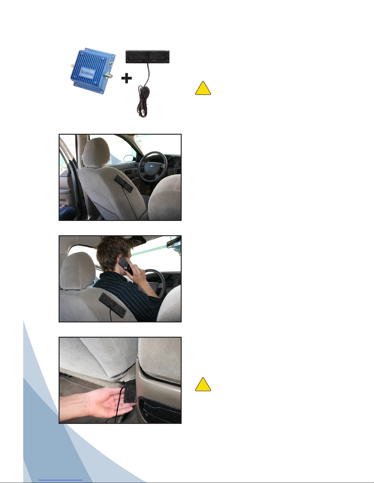
Installing the Low-Profile Antenna
Install the low-profile inside antenna 8-12
inches from where the cell phone or cellular
data card will be used.
Place the inside antenna on the side of the
driver’s seat for maximum performance.
Install the inside antenna at least 8 inches,
but not more than 12 inches, from where
the cell phone or cellular data card will be
used.
Install the inside antenna at the same angle
as the cell phone when held in use, or place
next to the laptop’s cellular data card. This
will maximize the signal strength.
For a more professional-looking installation,
the low-profile antenna may be slid under
the seat cover or leather, high on the
driver’s seat.
Warning: Do not install the low-profile
antenna within 4 inches of metal. (Metal found
inside the vehicle’s seat will not affect the
antenna’s performance.)
!
Signal Booster
Warning: The inside antenna must be
installed with a separation of at least 8 inches
from all persons and must not be located in
conjunction with any other antenna or signal
booster.
!
Low-profile
Antenna
Page 7
6
Contact Wilson Electronics Tech Support with any questions at 866-294-1660
Or email: [email protected] Hours: 7am to 6pm MST.
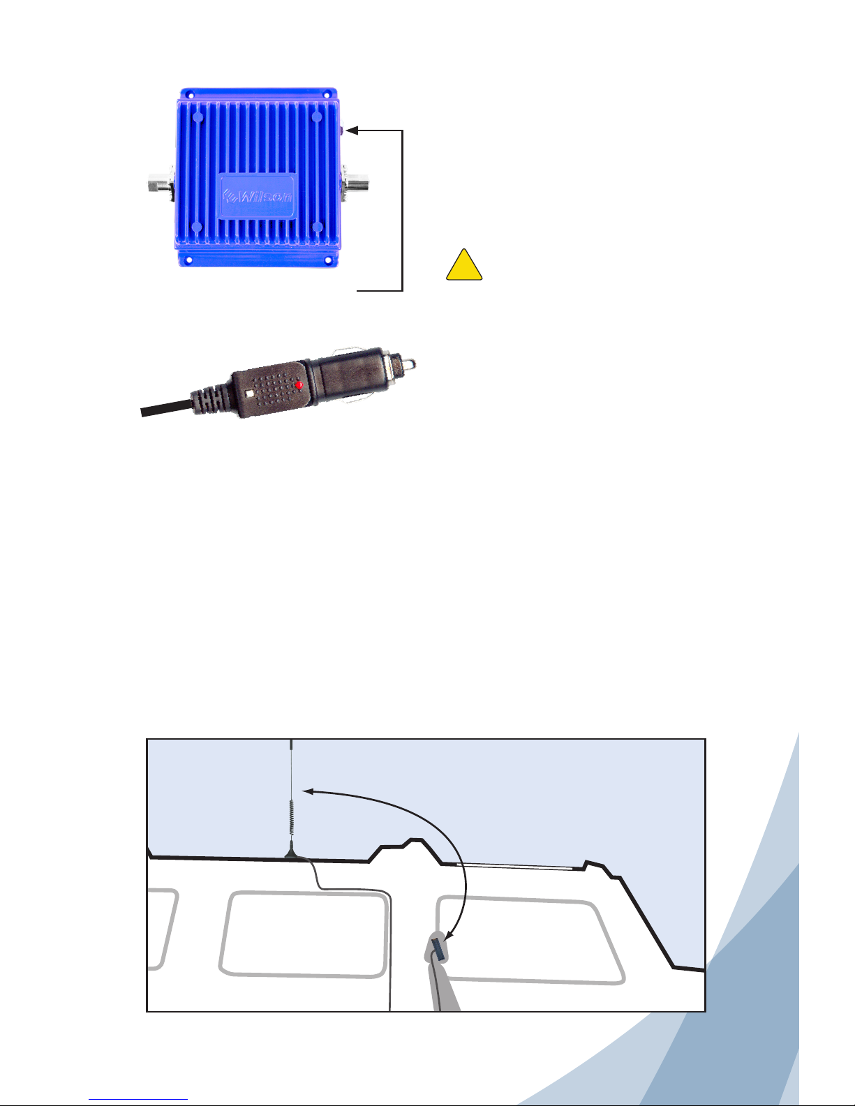
Powering up a Wilson Electronics Signal Booster
Make sure both the outside and inside
antenna cables are connected before
powering up the signal booster.
Connect the DC plug-in power supply
cable to the signal booster marked “Power”
and insert the large end into DC power
socket (the vehicle DC power adapter
outlet.)
The signal booster may remain on all the
time. However, leaving the signal booster
on in a vehicle when it is not running can
discharge the battery in a day or two.
A good option is to power the signal booster
through the ignition switch so the signal
booster is turned on and off with the vehicle.
NOTE: The aluminum casing of a Wilson signal booster will adjust very quickly to the ambient
temperature of its environment. For example, in the summer, when the inside of a car can reach 140
degrees Fahrenheit, the signal booster temperature may be 150 degrees or higher. The casing will
be hot to the touch, similar to a metal door handle or a steering wheel. Such high temperatures will
not damage the signal booster, nor do they pose a fire risk to the vehicle. As recommended in these
instructions, install the signal booster in a location with adequate ventilation, such as under the seat or
under the dashboard. Keep the area free of items that could block air flow to the signal booster.
IMPORTANT: Do not power up the signal
booster unless antenna cables are attached
to signal booster.
Distance between antennas
through a sunroof must be
5 feet or more.
Carefully insert the power cable.
Warning: Use only the power
supply cable provided in this package.
The power supply must be 12 V DC.
!
Separation of inside and outside antennas is very important. The metal roof of the vehicle
acts as a barrier and helps shield the two antennas from each other, preventing oscillation.
If the vehicle has a sunroof, it is important to separate the inside and outside antennas by at least
five feet. This prevents the signal booster from overloading or oscillating.
Page 8

7
Contact Wilson Electronics Tech Support with any questions at 866-294-1660
Or email: [email protected] Hours: 7am to 6pm MST.
8
Warnings and Recommendations
Warning: In a wireless installation, do not plug the signal booster directly into the
cell phone or cellular data card using an antenna adapter. It will damage
the cell phone or cellular data card.
Warning: Do not install the inside antenna within 4 inches of metal. (Metal found
inside the vehicle’s seat will not affect antenna performance.)
Warning: Do not use any type of glass-mount antenna with this signal booster.
The outside and inside antennas must be shielded from each other to
prevent oscillation.
Warning: Do not plug in the DC power supply until the outside and inside antenna
cables are attached to the signal booster.
Warning: RF Safety: The inside antenna must be installed with a separation of at
least 8 inches from all persons and must not be located in conjunction
with any other antenna or signal booster.
Warning: RF Safety: The outside antenna must be installed with a separation
of at least 20 inches from any of the vehicle’s occupants or nearby
persons and must not be located or operating in conjunction with any
other antenna or signal booster. All roof-mount antennas should be
centrally located on the roof of the vehicle. Mirror-mount antennas
should mounted as high above the roof line as possible and leave at
least 20 inches of separation from any persons near or around the
vehicle. Use of a cellular signal booster with an antenna gain higher
than 5.12 dBi is in violation of FCC regulations for which the offender is
fully liable. All Wilson Electronics mobile antennas are 5.12 dBi or less
in the 800 MHz band.
Warning: The inside antenna must be installed with a separation of at least 8
inches from all persons and must not be located in conjunction with
any other antenna or signal booster.
Page 9
8
Contact Wilson Electronics Tech Support with any questions at 866-294-1660
Or email: [email protected] Hours: 7am to 6pm MST.
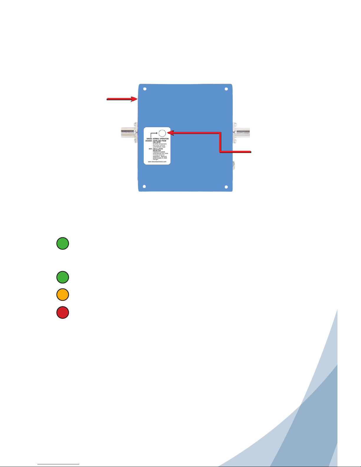
Understanding the Signal Booster Lights
Power Indicator Light
Shows green when the unit is turned on.
Signal Indicator Light
A green light indicates normal operation.
An orange light indicates overload from the cell tower. The signal booster has
temporarily shut down and will automatically reset.
A red light indicates that oscillation has been detected. The inside and outside
antennas are too close to one another. Increase the antenna separation distance,
then remove and replace the DC power cable to reset the light. If it still shows red,
repeat the procedure.
Power Indicator Light
(located on the side)
Signal Indicator Light
(located on the back)
Page 10

9
Contact Wilson Electronics Tech Support with any questions at 866-294-1660
Or email: [email protected] Hours: 7am to 6pm MST.
10
About Wilson Electronics
Wilson Electronics, Inc. has been a leader in the wireless communications industry for
nearly 40 years. The company designs and manufactures signal boosters, antennas and
related components that significantly improve cellular telephone signal reception and
transmission in a wide variety of applications, both mobile and in-building.
With extensive experience in antenna and signal booster research and design, the
company’s engineering team uses a state-of-the-art testing laboratory, including an
anechoic chamber and network analyzers, to fine-tune antenna designs and performance.
For its signal boosters, Wilson Electronics uses a double electrically insulated RF enclosure
and cell tower simulators for compliance testing.
All products are engineered and assembled in the company’s 55,000-square-foot
headquarters in St. George, Utah. Wilson Electronics has product dealers in all 50 states
as well as in countries around the world.
Page 11

10
Contact Wilson Electronics Tech Support with any questions at 866-294-1660
Or email: [email protected] Hours: 7am to 6pm MST.
30-Day Money-Back Guarantee
All Wilson Electronics products are protected by Wilson Electronics 30-day moneyback guarantee. If for any reason the performance of any product is not acceptable,
simply return the product directly to the reseller with a dated proof of purchase.
1-Year Warranty
Wilson Electronics signal boosters are warranted for one (1) year against defects in
workmanship and / or materials. Warranty cases may be resolved by returning the
product directly to the reseller with a dated proof of purchase.
Signal boosters may also be returned directly to the manufacturer at the consumer’s
expense, with a dated proof of purchase and a Returned Material Authorization (RMA)
number supplied by Wilson Electronics. Wilson Electronics shall, at its option, either
repair or replace the product. Wilson Electronics will pay for delivery of the repaired or
replaced product back to the original consumer if located within the continental U.S.A
This warranty does not apply to any signal boosters determined by Wilson Electronics
to have been subjected to misuse, abuse, neglect, or mishandling that alters or
damages physical or electronic properties.
RMA numbers may be obtained by phoning Technical Support at 866-294-1660.
Operation is subject to the following two conditions: (1) This device may not cause
interference and (2) this device must accept any interference, including interference that
may cause undesired operation of this device.
Disclaimer: The information provided by Wilson Electronics, Inc. is believed to
be complete and accurate. However, no responsibility is assumed by Wilson
Electronics, Inc. for any business or personal losses arising from its use, or for
any infringements of patents or other rights of third parties that may result from
its use.
Copyright © 2010 Wilson Electronics, Inc. All rights reserved.
Page 12
Wilson® Electronics, Inc.
Phone: 866-294-1660 www.wilsonelectronics.com Fax: 435-656-2432
Part #110520 AIG SBMW 028 / 11.17.10
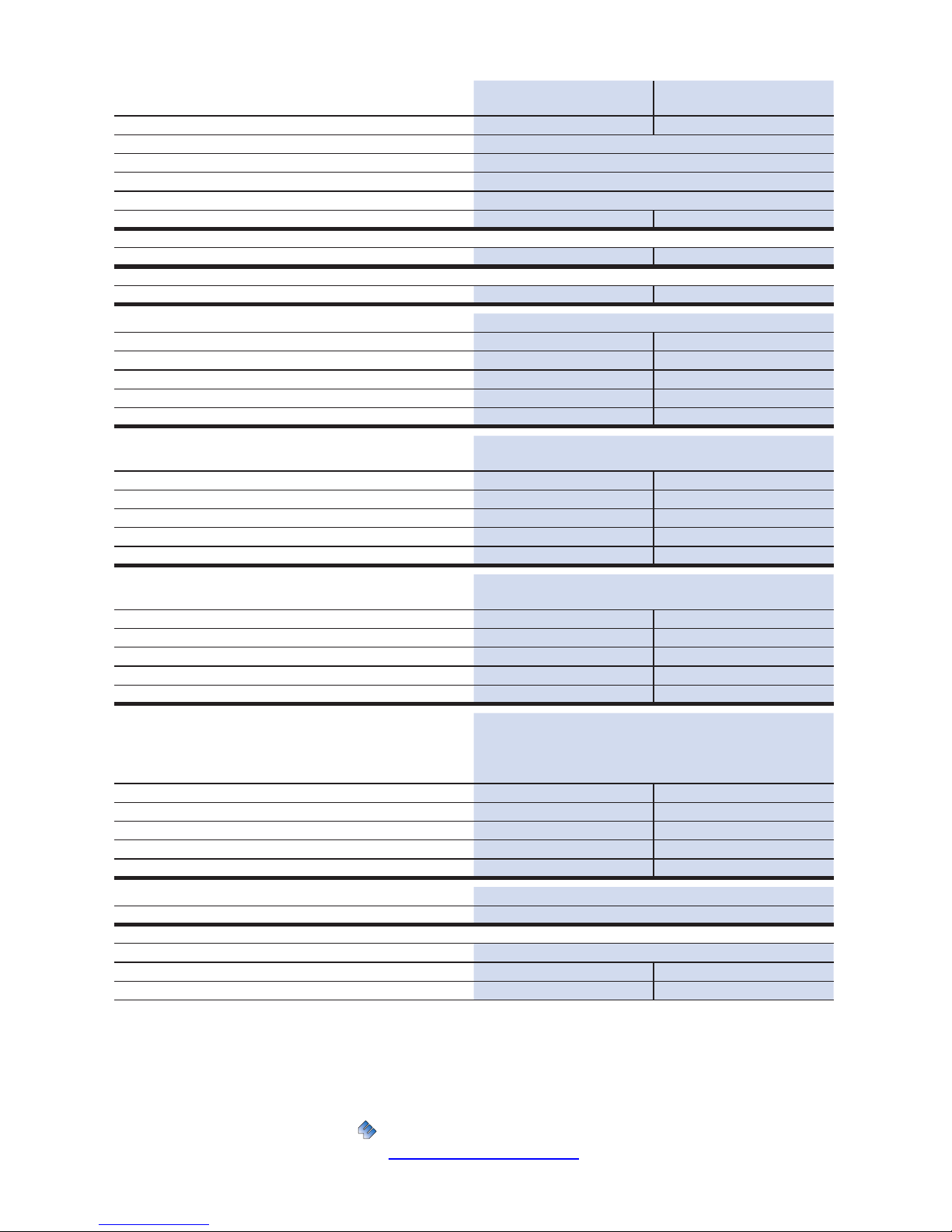
Signal Booster Specifications
Single Band Cellular
800 MHz Specifications
Single Band iDEN
800 MHz Specifications
Model Number 801101 804002
Connectors FME-Male
Impedance (input/output) 50 ohms
Dimensions 5.5 x 4.3 x 1.4 inch or 14 x 10.8 x 3.5 cm
Weight 1.32 lbs or 0.6 kg
Frequency 824-894 MHz 806-869 MHz
1
Passband Gain (nominal)
(uplink/downlink) 40 dB / 40 dB 40 dB / 40 dB max
2
20 dB Bandwidth (nominal)
(uplink/downlink) 50 MHz / 50 MHz
3
Power output for single cell phone (uplink)
CDMA +33.3 dBm
GSM +32.0 dBm
EDGE +31.5 dBm
AMPS +31.6 dBm
iDEN +32.0 dBm
4
Power output (uplink) for multiple
cell phones:
Number of
cell phones
Maximum Power
2 +20.3 dBm
3 +16.8 dBm
4 +14.3 dBm
5 +12.3 dBm
6 +10.8 dBm
Power output for single received channel
(downlink)
CDMA +2.7 dBm
GSM -5.2 dBm
EDGE -3.1 dBm
AMPS -5.0 dBm
iDEN +10.0 dBm
4
Power output for multiple received
channels (downlink).
Maximum Power
The maximum power is reduced by the
number of channels:
Number of
channels
2 -2.5 dBm
3 -6.0 dBm
4 -8.5 dBm
5 -10.5 dBm
6 -14.5 dBm
Noise Figure (typical) 3.5 dB nominal
Isolation (uplink/downlink) > 90 dB
Power Requirements
Signal Booster Voltage/Current 9-14 V, .5 A - 1.5 A
FCC ID: PWO824WV PWO806WV
5
IC: 4726A-824WV 4726A-806WV
Notes:
1. Nominal gain is the maximum gain at any frequency in the passband.
2. Nominal bandwidth is the difference between two frequencies that are adjacent to the passband where the amplification is 20 dB lower than the passband
amplification. One of the frequencies is lower than the passband and the other is higher.
3. The Manufacturer’s rated output power of this equipment is for single carrier operation. For situations when multiple carrier signals are present, the rating would
have to be reduced by 3.5 dB, especially where the output signal is re-radiated and can cause interference to adjacent band users. This power reduction is to be
by means of input power or gain reduction and not by an attenuator at the output of the device.
4. The maximum power for 2 or more simultaneous signals will be reduced by 6 dB every time the number of signals is doubled.
5. The term “IC” before the radio certification number only signifies that Industry Canada technical specifications were met.
 Loading...