

Page 1

In-Building
Wireless
Smart Technology™
Signal Booster
Contents:
Antenna Options and Accessories. . . . . . . . . . . . . . . . . . . 1
Before Getting Started / How It Works . . . . . . . . . . . . . . . 2
Installation Overview .............................3
Installing a Wilson Electronics Outside Antenna ........4
Installing a Wilson Electronics Inside Antenna . . . . . . . . .5
Installing a Wilson Electronics Signal Booster. . . . . . . . . . 6
Powering Up a Wilson Electronics Signal Booster . . . . . . 7
Understanding the Signal Booster Lights . . . . . . . . . . 8-10
Warnings and Recommendations ..................11
Factor Conversions .............................12
Distance Coverage Chart . . . . . . . . . . . . . . . . . . . . . . . . 13
Guarantee and Warranty .........................14
Signal Booster Specifications . . . . . . . . . . . . . .Back Cover
Wilson
®
Electronics, Inc.
Note: This manual contains important safety and operating information.
Please read and follow the instructions in this manual. Failure to do so
could be hazardous and result in damage to your signal booster.
Appearance of device and accessories may vary.
Page 2

1
Contact Wilson Electronics Technical Support Team with any questions at 866-294-1660
or email: [email protected]. Hours: 7 am to 6 pm MST.
2
Installation Instructions for the Following Wilson Electronics
Signal Boosters:
In-Building Wireless Cellular 50 dB Smart Technology™ Signal Booster
Model # 801105
FCC ID: PWO8011SB IC: 4726A-8011SB
In-Building Wireless Cellular 60 dB Smart Technology™ Signal Booster
Model # 801106 & 801108
FCC ID: PWO8011SB IC: 4726A-8011SB
In-Building Wireless PCS 60 dB Smart Technology™ Signal Booster
Model # 801306 FCC ID: PWO8013SB IC: 4726A-8013SB
Model # 801365 FCC ID: PWO8013SB Not for sale in Canada
In-Building Wireless iDEN 50 dB Smart Technology™ Signal Booster
Model # 804005
FCC ID: PWO8040SB IC: 4726A-8040SB
In-Building Wireless iDEN 60 dB Smart Technology™ Signal Booster
Model # 804006
FCC ID: PWO8040SB IC: 4726A-8040SB
In-Building Wireless EGSM 900 MHz 60 dB Smart Technology™ Signal Booster
Model # 801506 FCC ID: PWO274106SB IC: 4726A-274106SB
Model # 801606 Not for sale in U.S. and Canada
In-Building Wireless 800 MHz 70 dB Smart Technology™ Signal Booster
Model # 801170 & 801370 Not for sale in the U.S. and Canada.
Model # 801176 FCC ID: PWO8011SB Not for sale in Canada
The term “IC” before the radio certification number only signifies that Industry Canada
technical specifications were met.
A 13 dB 800 MHz Yagi Cellular Antenna (301111)
B 1900 MHz Yagi PCS Antenna (301124)
C 800 MHz Yagi Cellular Antenna (301129)
D Wide-Band Panel Antenna (301135)
E Dual-Polarity Dome Antenna (301123)
F Dual-Band Dome Antenna (301121)
G Splitters (see page 5)
H 50 Ohm Lightning Surge Protector (859902)
I Signal Booster Soft Cases (859909)
J Omni-Directional Antenna (301201)
K Marine Antenna (301130)
Antenna Options & Accessories
A
B
C
D E
F
H
I
J K
G
Appearance of device and accessories may vary.
Page 3

2
Contact Wilson Electronics Technical Support Team with any questions at 866-294-1660
or email: [email protected]. Hours: 7 am to 6 pm MST.
Before Getting Started
This guide will help you properly install Wilson Electronics In-Building Wireless Smart
Technology™ Signal Boosters. It is important to read through all of the installation steps
for your particular application prior to installing any equipment. Read through the
instructions, visualize where all the equipment will need to be installed and do a soft installation
before mounting any equipment. If you do not understand the instructions in full, seek
professional help, or contact Wilson Electronics Technical Support at 866-294-1660.
Inside this Package
Additional Required Equipment (sold separately)
• Outside Antenna (Yagi recommended)
• Inside dome, panel or low-profile antenna
• Antenna cable
How it Works
Wilson Electronics Signal Boosters are small, portable, bi-directional devices that deliver service
levels consistent with what would be expected in areas of high cell network coverage. They
amplify a weak or shadowed signal in mobile, marine and in-building applications.
When using a Wilson Electronics Signal Booster in conjunction with Wilson Electronics
antennas, the Outside Antenna will collect the cell tower signal and send it through the
cable to the Signal Booster. The signal is then amplified and transmitted from the Inside
Antenna to the surrounding area. Cell phones and cellular data cards in that area then
communicate with the improved signal. When a cell phone or cellular device transmits, the
signal is received by the Inside Antenna, amplified by the Signal Booster and transmitted
back to the cell tower through the Outside Antenna.
In-Building Wireless
Signal Booster
AC/DC power supply
(sold separately in 801175)
Page 4

3
Contact Wilson Electronics Technical Support Team with any questions at 866-294-1660
or email: [email protected]. Hours: 7 am to 6 pm MST.
4
Installation Overview
The following steps provide a summary of the Signal Booster/antenna installation process.
However, they are not a substitute for the complete installation instructions on the following
pages, which you should read thoroughly. Contact Wilson Electronics Technical Support
Department with any questions at 866-294-1660.
STEP 1: Install the Outside Antenna
Mount the Yagi antenna so that it points toward the cell tower and away from where the
Inside Antenna will be located. Depending on your Signal Booster model, the two antennas
will need 50-75 feet of separation (see illustrations on pages 5 and 6). Lightning Surge
Protection is recommended for all in-building installations (see page 6).
STEP 2: Install the Inside Antenna
Select a location in the center of where the signal needs to be amplified. Refer to the
instructions included with the Inside Antenna. (See illustration on page 5.)
STEP 3: Install the Signal Booster
Position the Signal Booster in a well-ventilated location near a power outlet. Attach the
Outside and Inside Antennas to the Signal Booster using Wilson 400 low loss cable
(available from Wilson Electronics). See page 6 for more information.
STEP 4: Power up the Signal Booster
IMPORTANT! Before connecting the power supply, ensure that both the Inside and Outside
Antenna cables are connected. Also ensure that all cell phones and cellular data cards
within 50 feet of the Inside Antenna are turned off. Plug in the supplied power supply
into the Signal Booster and then into a AC power strip (power supply sold separately in
801175). See page 7 for more information. Wilson
Electronics recommends that all AC
power supplies for home electronics be plugged into a AC Power Strip with at least a 1000
Joule rating.
STEP 5: Check the Signal Booster Lights
The PWR light should be green, indicating that the Signal Booster has power. If all other
lights are also green, the Signal Booster is operating properly; however, if you do not have
the desired signal coverage area, refer to pages 5, 6, 8, 9 and 10.
Note: If you are using an outdoor Yagi Antenna, it must be adjusted for maximum signal.
Page 5

4
Contact Wilson Electronics Technical Support Team with any questions at 866-294-1660
or email: [email protected]. Hours: 7 am to 6 pm MST.
Warning: The Outside Antenna must
be installed on an outdoor
permanent structure with a
separation of at least 20 feet
from all persons during
normal operation.
!
Cell Tower
RF Signal
Yagi External Antenna
Warning: Never point the front of the Yagi Antenna
toward the Inside Antenna - oscillation will
result, causing amber light and gain reduction.
!
NOT
CORRECT
CORRECT
Pointing toward
cell tower
Lightning
Surge Protector
(sold separately)
Signal Booster
Surge Protector
Power Strip recommended for all AC power supplies
To Outside
Antenna
Ground Wire
(not included)
To Inside
Antenna
Select a location on the roof of the building to install the Outside Antenna. Take extreme
care to ensure neither you nor the antenna come in contact with any electrical power lines.
Using a cell phone in test mode to find the strongest signal from the cell tower. For test
mode help, visit www.WilsonElectronics.com or call Technical Support at 866-294-1660.
Follow the specific antenna installation instructions included with the Outside Antenna.
A Yagi Antenna must be installed horizontally with the elements vertical and the drip hole on
the bottom. Ensure there is three feet of clearance in all directions surrounding the antenna.
Installing a Wilson Electronics Outside Antenna
Installing Lightning Protection
(sold separately)
Install the Lightning Surge Protector (LSP) close
to the Signal Booster. Attach the cable from the
Outside Antenna to the surge protector, using a
short length of low loss cable; attach one end to
the LSP and the other to the Outside Antenna
connector on the Signal Booster.
Ensure
the LSP is properly grounded. LSP may be
purchased at www.WilsonElectronics.com or
call 800-204-4104 (part #859902).
Page 6
5
Contact Wilson Electronics Technical Support Team with any questions at 866-294-1660
or email: [email protected]. Hours: 7 am to 6 pm MST.
6
Installing a Wilson Electronics Inside Antenna
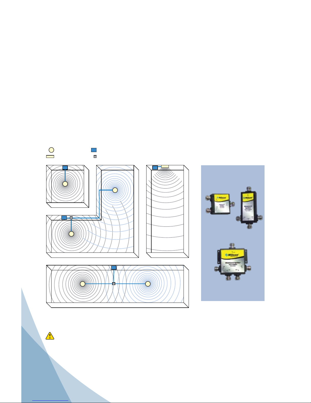
Select a suitable location for the Inside Antenna, preferably in the center of where the signal
needs to be amplified. To determine signal strength and coverage distance, refer to page
12 of this installation guide.
Follow the specific antenna installation instructions included with the Inside Antenna.
Wilson Electronics has several Inside Antenna options. The dome and Panel Antennas are
the most popular for in-building applications.
For a square room, a Dome Antenna will provide better coverage. (A)
For a rectangular room, a Panel Antenna will provide better coverage. (B)
In some cases, multiple Inside Antennas may be required (C & D). A signal may be “split”
by using a splitter. If using more than one Inside Antenna, a separation of at least 20 feet is
necessary between Inside Antennas.
Connect the cable from the Signal Booster to the Inside Antenna. For distances of 20 feet or
more, use Wilson 400 low loss cable to prevent significant signal loss.
= Dome Antenna
= Panel Antenna
= Splitter
= Signal Booster
A
BC
D
Warning: An Inside Antenna must have a separation distance from all persons that is
at least 12 inches for the 5.2 dBi Dome Antenna and 15 inches for the
7 dBi Panel Antenna.
Splitter Options:
2-way
(859957)
(sold separately)
3-way
(859980)
4-way
(859981)
Page 7
6
Contact Wilson Electronics Technical Support Team with any questions at 866-294-1660
or email: [email protected]. Hours: 7 am to 6 pm MST.
Installing a Wilson Electronics Signal Booster
Select a location to install the Signal Booster that is away from excessive heat, direct
sunlight, moisture and that has proper ventilation. Do not place the Signal Booster in an
air-tight enclosure.
Recommended installation locations for in-building Signal Boosters are:
In a closet, on a shelf and near a power outlet.
Run the Outside Antenna cable to the Signal Booster and attach it to the connector labeled
“Outside Antenna” on the Signal Booster. Run the Inside Antenna cable to the Signal
Booster and attach it to the connector labeled “Inside Antenna” on the Signal Booster.
Note: Be careful when plugging the connector in so as not to damage the center pins on
the connectors.
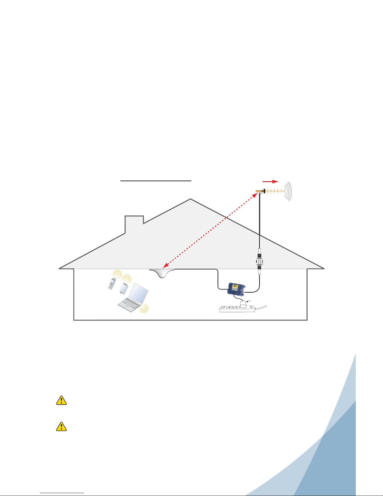
Connect the Outside Antenna to the Signal Booster with Wilson 400 low loss cable
(available from Wilson Electronics). Place the Inside Antenna in the center of the area
needing the amplified signal. It is important to have at least 50 feet of separation between
the Inside and Outside Antennas for the 50 dB Signal Boosters, 68 feet of separation
distance for the 60 dB PCS Signal Boosters and at least 75 feet of separation distance for
the 65 dB Signal Boosters.
AC/DC
Power Supply
Surge Protector Powerstrip (recommended)
Signal Booster
Lightning
Surge Protector
(sold separately)
Cell
Site
Supports
Multiple
Users
Inside Antenna
Optional Dome
Antenna Shown
Point Yagi antenna
away from Inside
Antenna
Outside
Antenna
1900 MHz Yagi
Antenna Shown
50 feet minimum
separation between Inside
and Outside Antenna for
50 dB cellular Signal Booster
68 feet for 60 dB PCS
Signal Booster
75 feet for 65 dB cellular Signal Booster
Antenna Separation
Warning: Connecting the Signal Booster directly to the cell phone with use of an
adapter will damage the cell phone.
Warning: Lightning protection is recommended for all installations (sold separately).
Take extreme care to ensure that neither you nor the antenna comes near
any electric power lines.
Page 8
7
Contact Wilson Electronics Technical Support Team with any questions at 866-294-1660
or email: [email protected]. Hours: 7 am to 6 pm MST.
8
Powering up a Wilson Electronics Signal Booster
1. IMPORTANT! Ensure that all cell phones and cellular data cards within 50 feet of the
Inside Antenna are turned off.
2. To verify proper installation of the Signal Booster and antennas, make sure that the
distance between the Inside and Outside Antennas is a minimum of 50 feet for the 50 dB
Signal Booster, 68 feet of separation distance for the 60 dB PCS Signal Booster, and 75
feet for the 65 dB cellular Signal Booster.
3. If you are using an outside Yagi Antenna, never point the front of the Yagi toward the
Inside Antenna.
4. Ensure that both the Outside Antenna cable and the Inside Antenna cable are connected
to the Signal Booster before powering up the Signal Booster.
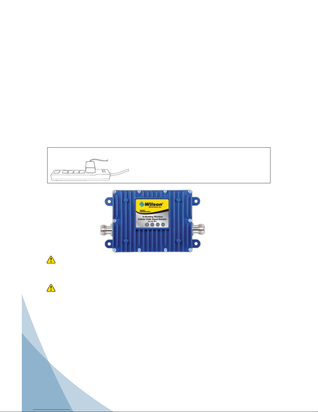
5. Plug the power supply into the Signal Booster input marked “POWER” (carefully, to avoid
damaging the center pin) and then into a AC Power Strip.
NOTE: The aluminum casing of a Wilson Electronics Signal Booster will adjust very
quickly to the ambient temperature of its environment. For example, in the
summer, when the attic of a house can easily exceed 140 degrees Fahrenheit,
the Signal Booster temperature may be 10 or more degrees higher. The casing
will be hot to the touch. Such high temperatures will not damage the Signal
Booster, nor do they pose a fire risk. As recommended in these instructions,
install the Signal Booster in a location with adequate ventilation. Keep the area
free of items that could block air flow to the Signal Booster.
Warning: Use only the power supply provided in this package. Use of a non-Wilson
Electronics product may damage your equipment (power supply sold
separately in 801175).
Warning: Verify that both the Outside Antenna and the Inside Antenna are connected
to the Signal Booster before powering up the Signal Booster.
IMPORTANT NOTICE
It is very important to power your Signal Booster using a •
surge protected AC Power Strip with at least a 1000 Joule
rating.
Failure to do this will void your warranty in the • event of a
power surge or lightning strike.
Page 9
8
Contact Wilson Electronics Technical Support Team with any questions at 866-294-1660
or email: [email protected]. Hours: 7 am to 6 pm MST.
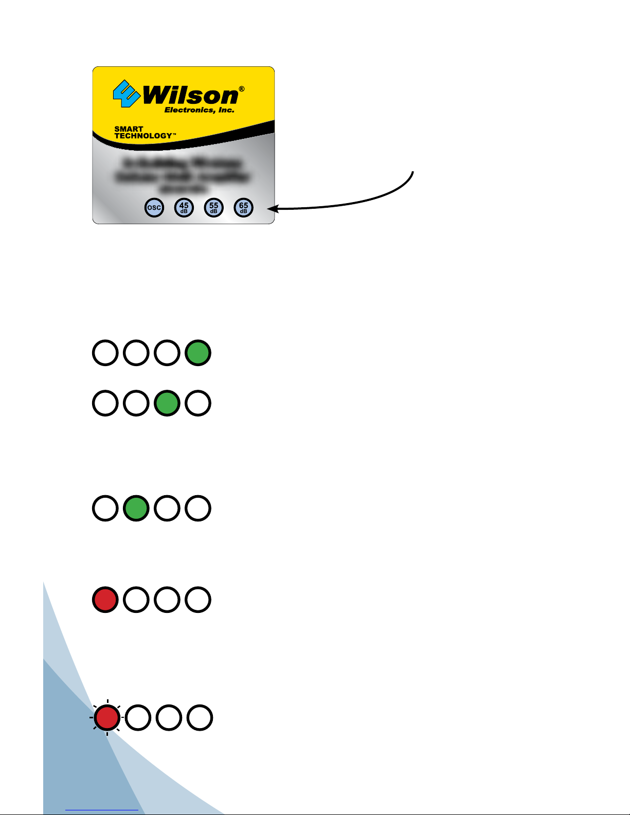
The Signal Booster is equipped with sensitive electronics designed to detect Signal Booster
oscillation or cell phone overload, both of which can hamper Signal Booster performance.
The Signal Booster is designed to automatically reduce gain or, if necessary, shut down
to prevent or compensate for these conditions. Oscillation or overload can be caused by
improper equipment installation -- understanding the Signal Booster lights will help you
identify and solve potential problems.
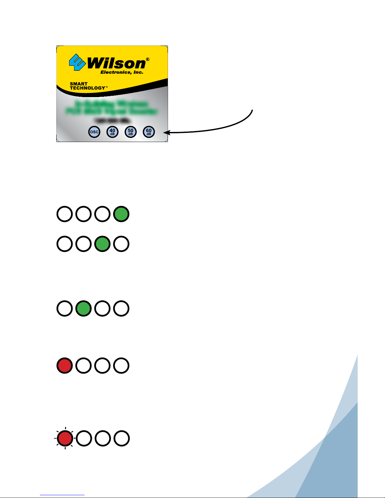
OSC
40 50 60
When the Signal Booster is initially powered on, the 60 light
will turn green. This indicates the Signal Booster is working at
the proper gain level.
If the 50 light is green, an oscillation has been detected and
the Signal Booster is powering down. Verify that the outside
Yagi Antenna is pointed away from the Inside Antenna and
not across the roof of the building. If need be, redirect the
Yagi Antenna so that it is pointing away from the Inside
Antenna. Then, reset the Signal Booster by disconnecting and
reconnecting the power supply.
If the 40 light is green, the Signal Booster is continuing to
power down. Try operating the cell phone farther away from
the Inside Antenna. If need be, redirect the Yagi Antenna so
that it is pointing away from the Inside Antenna. Then, reset
the Signal Booster by disconnecting and reconnecting the
power supply.
If the OSC light is solid red, the Signal Booster has shut
down to prevent oscillation. Try operating the cell phone
farther away from the Inside Antenna. Verify that the outside
Yagi Antenna is pointed away from the Inside Antenna and
not across the roof of the building. If need be, redirect the
Yagi Antenna so that it is pointing away from the Inside
Antenna. Then, reset the Signal Booster by disconnecting and
reconnecting the power supply.
If the OSC light is blinking red, the Signal Booster has shut
down to prevent a receive overload. Try moving the Outside
Antenna farther away from the cell tower.
OSC
40 50 60
OSC
40 50 60
OSC
40 50 60
If your Signal Booster has this
light configuration refer to the
instructions below.
Understanding the Signal Booster Lights
OSC
40 50 60
Page 10
9
Contact Wilson Electronics Technical Support Team with any questions at 866-294-1660
or email: [email protected]. Hours: 7 am to 6 pm MST.
10
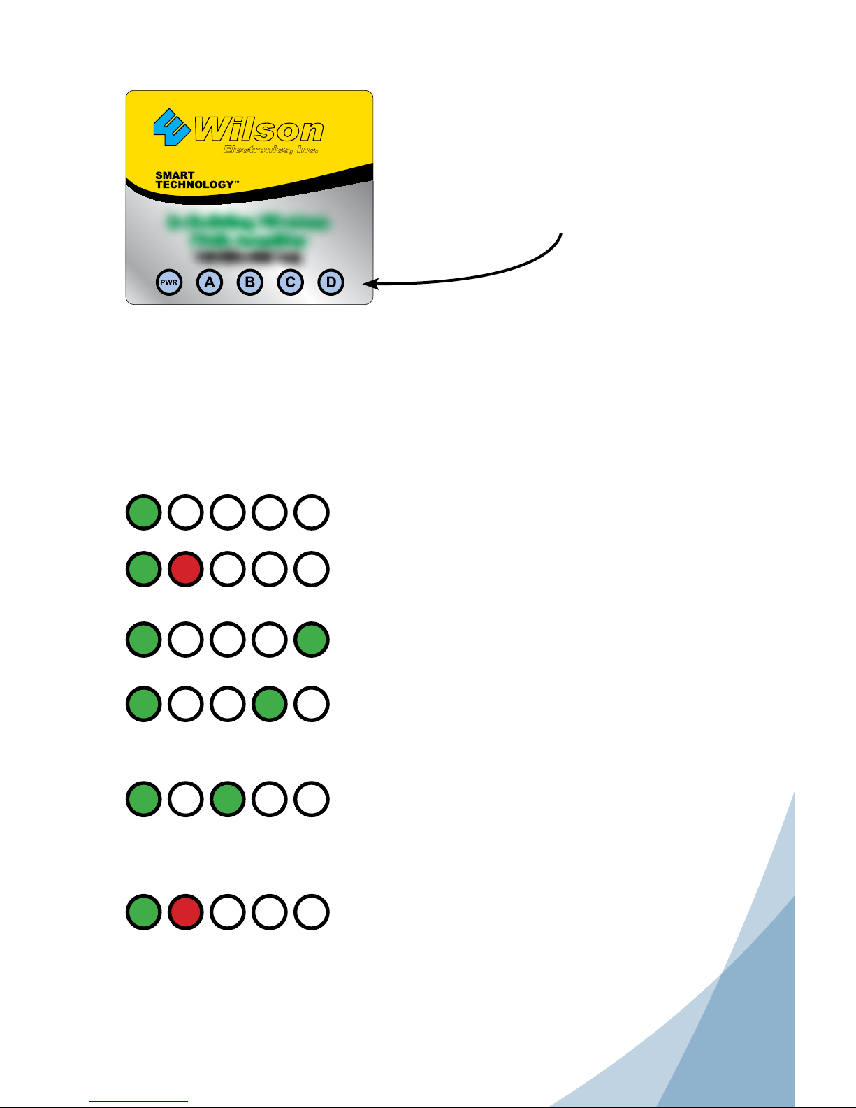
The Signal Booster is equipped with sensitive electronics designed to detect Signal Booster
oscillation or cell phone overload, both of which can hamper Signal Booster performance.
The Signal Booster is designed to automatically reduce gain or, if necessary, shut down
to prevent or compensate for these conditions. Oscillation or overload can be caused by
improper equipment installation, understanding the Signal Booster lights will help you identify
and solve potential problems.
OSC
45 55 65
When the Signal Booster is initially powered on, the 65 light
will turn green. This indicates the Signal Booster is working at
the proper gain level.
If the 55 light is green, an oscillation has been detected and
the Signal Booster is powering down. Verify that the outside
Yagi Antenna is pointed away from the Inside Antenna and
not across the roof of the building. If need be, redirect the
Yagi Antenna so that it is pointing away from the Inside
Antenna. Then, reset the Signal Booster by disconnecting
and reconnecting the power supply.
If the 45 light is green, the Signal Booster is continuing to
power down. Try operating the cell phone farther away from
the Inside Antenna. If need be, redirect the Yagi Antenna so
that it is pointing away from the Inside Antenna. Then, reset
the Signal Booster by disconnecting and reconnecting the
power supply.
If the OSC light is solid red, the Signal Booster has shut down
to prevent osciallation. Try operating the cell phone farther
away from the Inside Antenna. Verify that the outside Yagi
Antenna is pointed away from the Inside Antenna and not
across the roof of the building. If need be, redirect the Yagi
Antenna so that it is pointing away from the Inside Antenna.
Then, reset the Signal Booster by disconnecting and
reconnecting the power supply.
OSC
45 55 65
OSC
45 55 65
OSC
45 55 65
If your Signal Booster has this
light configuration refer to the
instructions below.
Understanding the Signal Booster Lights
OSC
45 55 65
If the OSC light is blinking red, the Signal Booster has shut
down to prevent a receive overload. Try moving the Outside
Antenna farther away from the cell tower.
Page 11
10
Contact Wilson Electronics Technical Support Team with any questions at 866-294-1660
or email: [email protected]. Hours: 7 am to 6 pm MST.
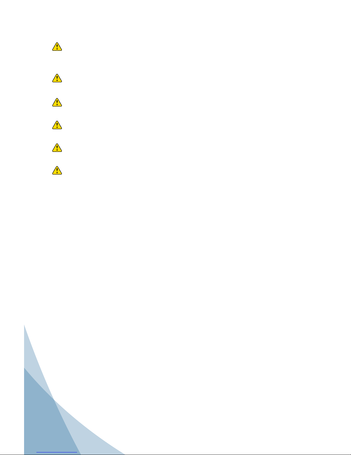
The Signal Booster is equipped with sensitive electronics designed to detect Signal Booster
oscillation or cell phone overload, both of which can hamper Signal Booster performance.
The Signal Booster is designed to automatically reduce gain or, if necessary, shut down
to prevent or compensate for these conditions. Oscillation or overload can be caused by
improper equipment installation -- understanding the Signal Booster lights will help you
identify and solve potential problems.
PWR
A B C D
PWR
A B C D
PWR
A B C D
PWR
A B C D
PWR
A B C D
PWR
A B C D
The power light will turn green when the Signal Booster
is initially powered on.
A BLINKING red light indicates a cell tower overload.
Move the Outside Antenna farther away from the cell
tower.
When the D light is green, the Signal Booster is working
at proper gain level (peak performance).
If light C is green but D is out, an oscillation has been
detected and the Signal Booster is powering down. To
remedy this, turn the Outside Antenna slightly away from
the Inside Antenna until the D light turns green.
If light B is green and C and light D are off, an oscillation
has been detected and the Signal Booster is powering
down. To remedy this, turn the Outside Antenna slightly
away from the Inside Antenna until the D light turns
green.
If light A is solid red, the Signal Booster has shut down to
prevent an oscillation. To remedy this, turn the Outside
Antenna slightly away from the cell tower. The Signal
Booster will reset automatically but may also be reset by
disconnecting and reconnecting the power supply.
Wilson
®
Electronics, Inc.
TM
If your Signal Booster has this
light configuration refer to the
instructions below.
Understanding the Signal Booster Lights
Page 12
11
Contact Wilson Electronics Technical Support Team with any questions at 866-294-1660
or email: [email protected]. Hours: 7 am to 6 pm MST.
12
Warnings and Recommendations
Warning: The Yagi Antenna must always be located so the back or side points to the
Inside Antenna. Never point the front of the Yagi Antenna toward the Inside
Antenna – oscillation will result, causing a red light and gain reduction.
Warning: The Outside Antenna must be installed on an outdoor permanent structure
with a separation of at least 20 feet from all persons during normal operation.
Warning: Connecting the Signal Booster directly to the cell phone with use of an
adapter will damage the cell phone.
Warning: Connect both the Outside and Inside Antenna cables to the Signal Booster
before powering up the Signal Booster.
Warning: Use only the power supply provided in this package. Use of a non-Wilson
Electronics product may damage your equipment.
Warning: RF Safety: An Inside Antenna must have a separation distance from all
persons that is at least 12 inches for the 5.2 dBi dome antenna and 15
inches for the 7 dBi panel Antenna.
Lightning protection is recommended for all in-building installations.
Finding Signal Strength and Calculating Coverage Distance
Signal strength and the corresponding coverage distance you can expect to achieve with your
Signal Booster/antenna system are based on a combination of several factors: the received
signal strength of your cell phone alone, the signal gain achieved by your Signal Booster and
antennas and the signal loss from cables, taps and splitters you may be using.
To calculate your approximate signal coverage distance, you can enter this information into our
Coverage Area Calculator on the Technical Support page on our website
www.WilsonElectronics.com. If you prefer, you can manually calculate your approximate signal
coverage distance using the instructions below and on the following two pages.
First, measure the Outside Signal Level (OSL) at the intended Outside Antenna location
using a cell phone in test mode. (For assistance, visit the Phone Test Modes section on the
Technical Support page on our website or call 866-294-1660.) The OSL will always be a
negative number. (Even if the cell phone shows a positive number, you will need to change it to
a negative for this calculation). Maximum signal strength is usually about -50. When the signal
weakens to about -100 or worse, the call may be dropped.
Depending on the model, your Signal Booster gain (AG) will be 50, 60 or 65 dB (see the label
on your Signal Booster or the specification table on the back cover of this guide). Your Inside
and Outside Antennas will also add signal gain, again depending on the antenna models you
are using (see the table on page 12).
You will also experience some signal loss from cables, splitters and taps used to connect your
system (see the table on page 13).
Page 13
12
Contact Wilson Electronics Technical Support Team with any questions at 866-294-1660
or email: [email protected]. Hours: 7 am to 6 pm MST.
Factor Conversions
Using the table below, find and circle the appropriate decibel (dB) numbers that correspond
to the equipment in your particular system. Be sure to choose your numbers from the
appropriate frequency column based on the service you receive (iDEN, Cellular or PCS).
Frequency
iDEN
851
Cellular
869
PCS
1930
Antenna Factor (AF)
Low Profile (inside) +3 dB +3 dB +3 dB
Dual-Band Panel (inside) +7 dB +7 dB +7 dB
Dual-Band Dome (inside) +2 dB +2 dB +2 dB
Dual-Polarity Dome (inside) +5 dB +5 dB +5 dB
Yagi 806-939 MHz Cellular (outside) +13 dB +13 dB +13 dB
Yagi 800-900 MHz Cellular (outside) +10 dB +10 dB +10 dB
Yagi 1800-1900 MHz PCS (outside) +14 dB +14 dB +14 dB
Cable Factor (CF)
20’ RG 58 -4 dB -4 dB -7 dB
20’ Wilson 400 -3 dB -3 dB -4 dB
30’ Wilson 400 -3 dB -3 dB -5 dB
50’ Wilson 400 -4 dB -4 dB -7 dB
100’ Wilson 400 -7 dB -7 dB -10 dB
Splitter Factor (SF) -3 dB -3 dB -3 dB
Tap Factor (TF)
(depends on model - refer to tap label) -6/-10 dB -6/-10 dB -6/-10 dB
Use the following formula to calculate your Signal Strength (S). Write in your numbers
as appropriate. Be sure to account for the length of all cable, inside and out. Add up the
numbers for all taps and/or splitters (if you are not using any, enter 0). Remember, AG and
AF will be positive numbers; OSL, CF, TF, SF and S will be negative.
OSL + AG + AF + CF + SF + TF = S
Once you have calculated your signal strength, use the graph on the following page to
determine approximate coverage distance. See below for a sample calculation.
Sample Signal Strength and Coverage Calculation
This example assumes an OSL of -90, use of a 60 dB Cellular Signal Booster, an 806-939
MHz Yagi Antenna and a low profile Inside Antenna with 100 total feet of inside and outside
9913 cable with no splitters or taps.
OSL -90 (always a negative number) found on cell phone in test mode
AG +60 gain
AF +16 dB gain (+13 dB for the Yagi Antenna and +3 dB for the low-profile antenna)
CF -7 dB loss
SF 0 (none used)
TF 0 (none used)
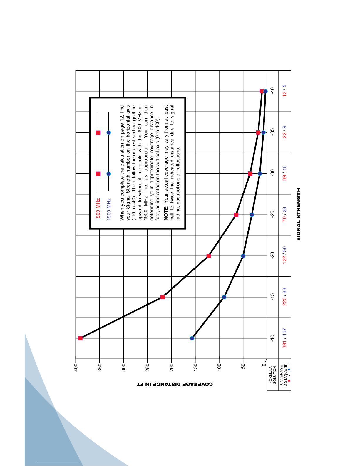
Formula: -90 + 60 + 16 + -7 + 0 + 0 = -21
With a signal strength of -21, coverage distance would be
approximately 120 feet from the Inside Antenna.
Page 14
13
Contact Wilson Electronics Technical Support Team with any questions at 866-294-1660
or email: [email protected]. Hours: 7 am to 6 pm MST.
14
0
COVERAGE
DISTANCE (ft)
FORMULA
SOLUTION
50
100
150
200
250
300
350
400
-10 -15 -20 -25 -30 -35 -40
391 / 157 220 / 88 122 / 50 70 / 28 39 / 16 22 / 9 12 / 5
SIGNAL STRENGTH
INSIDE BUILDING COVERAGE DISTANCE
COVERAGE DISTANCE IN FT
800 MHz
1900 MHz
When you complete the calculation on page 12, find
your Signal Strength number on the horizontal axis
(-10 to -40). Then, follow the nearest vertical gridline
upward to where it intersects with the 800 MHz or
1900 MHz line, as appropriate. You can then
determine your approximate coverage distance in
feet, as indicated on the vertical axis (0 to 400).
NOTE: Your actual coverage may vary from at least
half to twice the indicated distance due to signal
fading, obstructions or reflections.
Inside Building Coverage Distance
Page 15
14
Contact Wilson Electronics Technical Support Team with any questions at 866-294-1660
or email: [email protected]. Hours: 7 am to 6 pm MST.
30-Day Money-Back Guarantee
All Wilson Electronics products are protected by Wilson Electronics 30-day
money-back guarantee. If for any reason the performance of any product is not
acceptable, simply return the product directly to the reseller with a dated proof of
purchase.
1-Year Warranty
Wilson Electronics Signal Boosters are warranted for one (1) year against defects
in workmanship and/or materials. Warranty cases may be resolved by returning
the product directly to the reseller with a dated proof of purchase.
Signal Boosters may also be returned directly to the manufacturer at the
consumer’s expense, with a dated proof of purchase and a Returned Material
Authorization (RMA) number supplied by Wilson Electronics. Wilson Electronics
shall, at its option, either repair or replace the product. Wilson Electronics will
pay for delivery of the repaired or replaced product back to the original consumer
within the continental United States.
This warranty does not apply to any Signal Boosters determined by Wilson
Electronics to have been subjected to misuse, abuse, neglect, or mishandling
that alters or damages physical or electronic properties.
Failure to use a surge protected AC Power Strip with at least a 1000 Joule rating
will void your warranty.
RMA numbers may be obtained by phoning Technical Support at 866-294-1660.
This device complies with Part 15 of FCC rules. The transaction is subject to two
conditions: (1) This device may not cause harmful interference, and (2) this device
must accept any interference received, including interference that may cause undesired
operation. Changes or modications not expressly approved by Wilson Electronics could
void the authority to operate this equipment.
Disclaimer: The information provided by Wilson Electronics, Inc. is believed to
be complete and accurate. However, no responsibility is assumed by Wilson
Electronics, Inc. for any business or personal losses arising from its use, or for
any infringements of patents or other rights of third parties that may result from its
use.
Wilson
®
Electronics, Inc.
3301 East Deseret Drive, St. George, UT 84790
For additional Technical Support visit www.WilsonElectronics.com
or email at: [email protected]
Phone: 866-294-1660 Local: 435-673-5021 Fax: 435-656-2432
www.twitter.com/WilsonCellular www.facebook.com/WilsonCellular
One or more of the following U.S. Patent numbers may apply to the Signal Booster in this
product – D596,614; D596,615; D563,381;7,729,669; 7,486,929; 7,729,656; 7,409,186;
7,783,318; 7,684,838; 12,714,994.
Copyright © 2012 Wilson Electronics, Inc. All rights reserved.
Page 16
Part #110434_Rev33_01.04.12
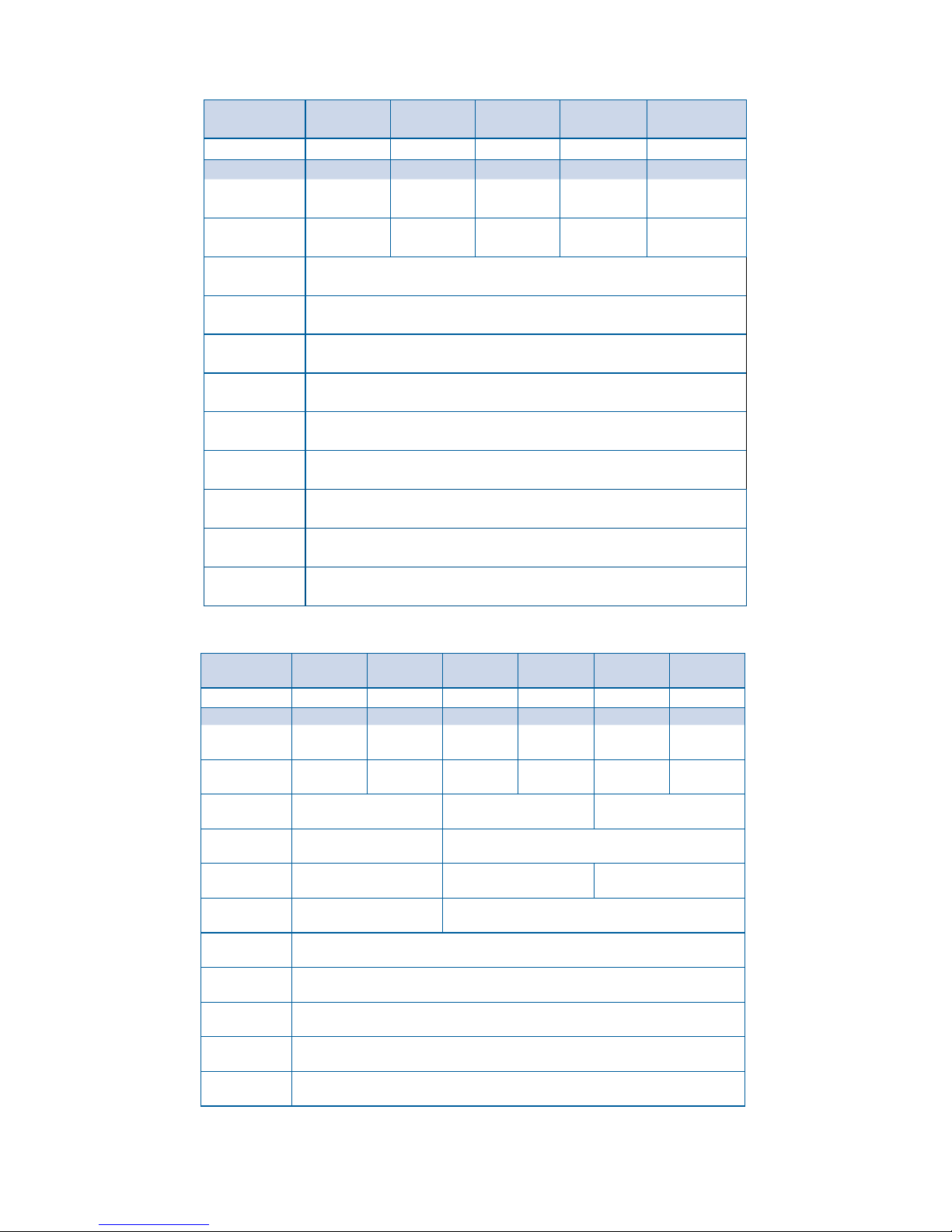
In-Building Wireless Signal Booster Specifications (iDEN, PCS, EGSM & DCS)
Model/Part
Number
iDEN
# 804005
iDEN
# 804006
PCS
# 801306
PCS
# 801365
EGSM
#801506
DCS
#801606
Not for sale in
Canada
Not for sale in the
U.S. or Canada
Frequency
Uplink 806-821
MHz 806-821 MHz 1850-1910 MHz 1850-1910 MHz 880-915 MHz 1710-1755 MHz
Downlink 851-866 MHz 851-866 MHz 1930-1990 MHz 1930-1990 MHz 925-960 MHz 1805-1880 MHz
Gain 50 dB 60 dB 60 dB 65 dB 60dB 60dB
Max Output 3 watts 2 watts 3 watts
AGC Limit
(uplink)
+ 30 dBm +30 dBm
Noise Figure 3-4 dB typical 4 dB typical 3 dB typical
Flatness
(uplink/downlink)
± 2.5 dB ± 4 dB
Isolation
(uplink/downlink)
> 90 dB
Power
Requirements
Input: 100-240 V AC 50/60 Hz 0.6 A / Output: 6 V DC 3 A
Connectors N-Female 50 ohms
Dimensions 5.6 x 3.6 x 1.7 (inch) / 14.2 x 9.1 x 4.4 (cm)
Weight 1.5 lbs / 0.7 kg
In-Building Wireless Signal Booster Specifications (GSM & Cellular)
Model/Part
Number
Cellular
# 801105/801175
Cellular
# 801106
Cellular
#801108
Cellular
#801110
Cellular
#801165
Frequency
Uplink 824-849
MHz 824-849 MHz 824-835 MHz 835-849 MHz 824-849 MHz
Downlink 869-894 MHz 869-894 MHz 869-880 MHz 880-894 MHz 869-894 MHz
Gain 50 dB 60 dB
Channel A
60 dB
Channel B
60 dB
65 dB
Max Output 3 watts
AGC Limit
(uplink)
+ 30 dBm
Noise Figure 3-4 dB typical
Flatness
(uplink/downlink)
± 2.5 dB
Isolation
(uplink/downlink)
> 90 dB
Power
Requirements
Input: 100-240 V AC 50/60 Hz 0.6 A / Output: 6 V DC 3 A
Connectors N-Female 50 ohms
Dimensions 5.6 x 3.6 x 1.7 (inch) / 14.2 x 9.1 x 4.4 (cm)
Weight 1.5 lbs / .7kg
The Manufacturer’s rated output power of this equipment is for single carrier operation. For situations when multiple carrier signals are present, the
rating would have to be reduced by 3.5 dB, especially where the output signal is re-radiated and can cause interference to adjacent band users.
This power reduction is to be by means of input power or gain reduction and not by an attenuator at the output of the device.
 Loading...