

Page 1
Need help? www.WilsonElectronics.com
Tech Support 866-294-1660
Mon.- Fri. Hours: 7 am to 6 pm MST
Mobile 4G
™
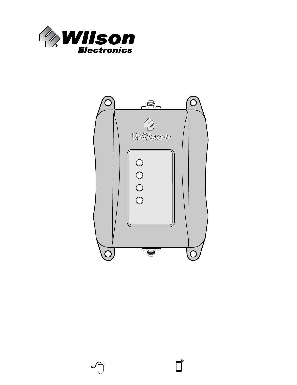
Cellular Signal Booster
460021
Page 2
2
Need help? www.WilsonElectronics.com
Tech Support 866-294-1660
Mon.- Fri. Hours: 7 am to 6 pm MST
! !
THE ALUMINUM CASING OF YOUR SIGNAL BOOSTER
WILL ADJUST TO THE TEMPERATURE OF ITS
ENVIRONMENT, BUT IS DESIGNED TO PROTECT THE
SIGNAL BOOSTER TECHNOLOGY. FOR EXAMPLE, IN THE SUMMER,
THE SIGNAL BOOSTER CASE MAY BE AS HOT AS 150 DEGREES
INSIDE YOUR VEHICLE. THESE HIGH TEMPERATURES WILL NOT
DAMAGE THE SIGNAL BOOSTER, NOR DO THEY POSE A FIRE
RISK TO THE VEHICLE. AGAIN, BE SURE TO PLACE YOUR SIGNAL
BOOSTER IN A LOCATION WITH ADEQUATE VENTILATION AND
AWAY FROM DIRECT SUNLIGHT OR MOISTURE.
THE MOBILE 4G SIGNAL
BOOSTER MAY REMAIN
ON, IN VEHICLES WHOSE
12V DC POWER SOURCES DO NOT
AUTOMATICALLY SHUTDOWN WHEN
THE VEHICLE IS TURNED OFF. THIS
COULD RESULT IN DISCHARGING THE
VEHICLES BATTERY IN ONE TO TWO
DAYS.
Installation Instructions for the Following Wilson Electronics Signal Boosters:
Mobile 4G SmarTech ™ Signal Booster
Model # 460021 FCC ID: PWO460021 IC: 4726A-460021
The term “IC” before the radio certication number only signies that Industry Canada technical specications were met.
Contents
Package Contents ....................................................3
Before Getting Started ................................................3
Installation ..........................................................3
Troubleshooting & Understanding Lights .................................5
Additional FAQ .......................................................6
Outside Antenna Options ..............................................7
Safety Guidelines ....................................................8
Signal Booster Specifications ..........................................9
Guarantee and Warranty ...................................... Back Cover
Page 3
3
Need help? www.WilsonElectronics.com
Tech Support 866-294-1660
Mon.- Fri. Hours: 7 am to 6 pm MST
Before Getting Started
Before you install your Mobile 4G
Booster and start enjoying improved
cellular reception please do the following:
1. Read through all the installation
steps. This will help you know what
to expect from start to nish.
2. Watch the YouTube video
demonstrating the Mobile 4G Signal
Boost installation at:
wilsonelectronics.com/
Mobile4Gvideo
3. Familiarize yourself with all
materials in your product package.
This will allow you to know which
pieces are referenced in the
instructions.
Installation
You can install your Mobile 4G
Signal Booster in your vehicle using
the following steps. NOTE: Before
completing your installation, create
a “soft” installation by putting the
components of your Mobile 4G Signal
Booster in place and testing the
operation before mounting equipment.
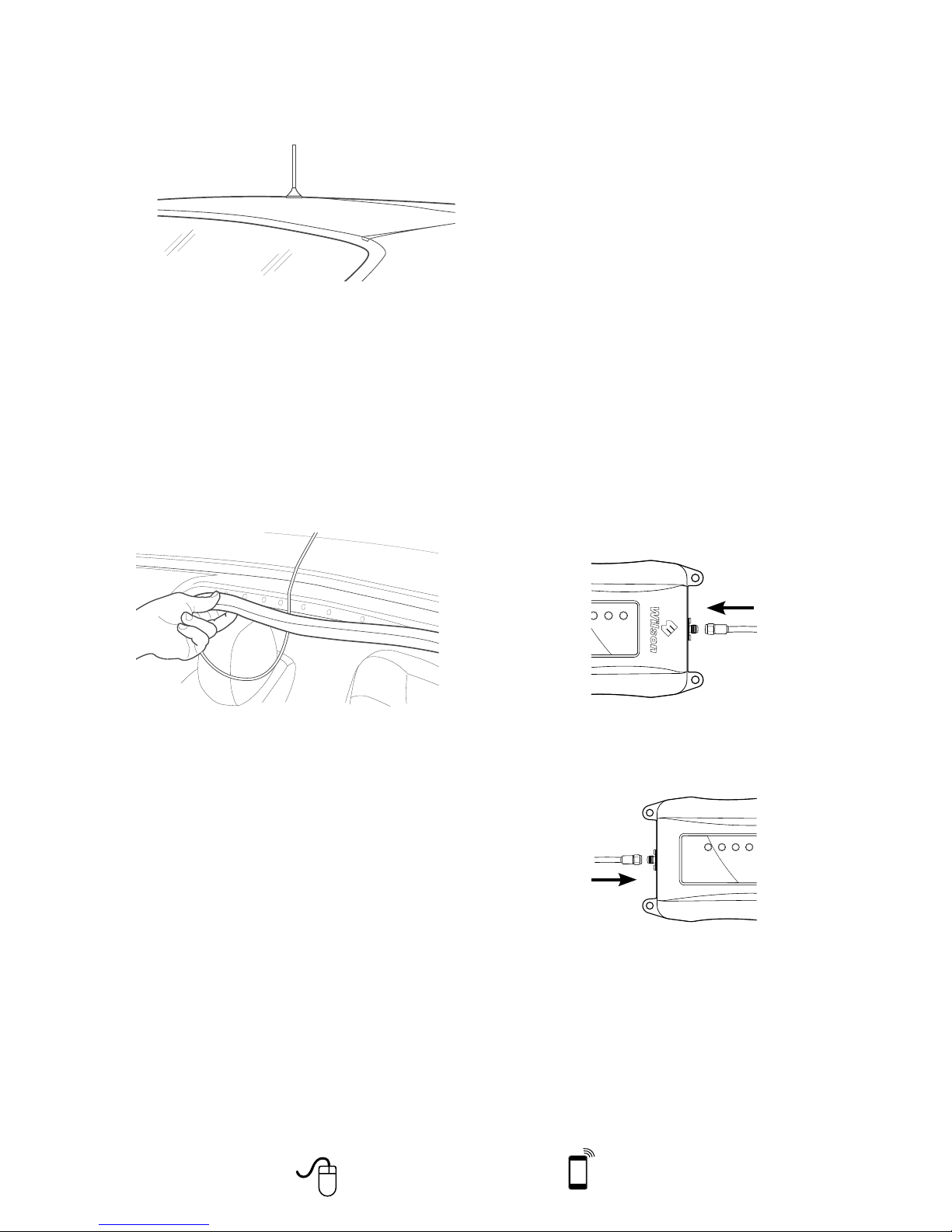
1. Install the outside antenna. Select a
location on top of the car that is:
• Near the center of the vehicle’s roof.
• At least 12 inches from any other
antennas.
• Free of obstructions.
• At least 6 inches from any
windows (including sunroofs).
• At least 8 inches from any people.
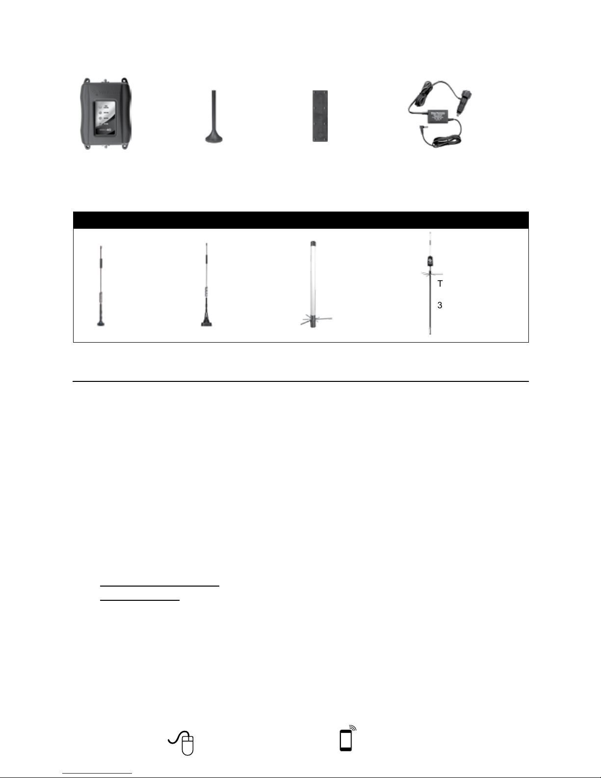
Package Contents
Mobile 4G
™
Signal Booster
Mini-Mag
Outside Antenna
301126
Slim Low Profile
Inside Antenna
301152
DC Power Supply
6V / 2A
859913
Optional Antennas
12” Mag Mount
Outside Antenna
311103
NMO
Outside Antenna
311104-5810
Marine
Outside Antenna
311130-5810
Trucker
Outside Antenna
311101
Appearance of device and accessories may vary.
Page 4
4
Need help? www.WilsonElectronics.com
Tech Support 866-294-1660
Mon.- Fri. Hours: 7 am to 6 pm MST
The outside antenna must be installed
vertically on a metallic surface.
2. Run the outside antenna cable
into the car. The cable is strong
enough that it may be shut in most
vehicle doors without damaging the
cable. For a cleaner look, carefully
pull down the door seal, run the
cable under the seal, and push the
seal back into place. This method
reduces wear on the cable as the
door opens and closes.
3. Install the Low-Prole inside antenna.
• Identify a place on the right side
of the driver’s seat to mount the
inside antenna. The location
should be at least 18 inches from
where the cellular device will be
used.
• Install the inside antenna at the
same angle as the cell phone
when held in use or near the
laptop’s cellular data card to
maximize signal strength.
For a more professional look,
you can install the inside antenna
underneath a car seat cover or
upholstery.
• When you have tested the
functionality of your Mobile 4G
Signal Booster, mount the inside
antenna by peeling off the backing
of the Velcro
®
and attach it to your
selected location on the seat and
secure the inside antenna.
4. Place and connect the Mobile 4G
Signal Booster.
• Select a location for the Signal
Booster that is free from excessive
heat, direct sunlight and moisture
and that has proper ventilation.
Good locations include underneath
a seat or under the dashboard.
• Connect the wire from the outside
antenna to the port labeled
“outside antenna” on the Signal
Booster.
• Connect the wire from the inside
antenna to the port labeled “inside
antenna” on the Signal Booster.
• Plug the power adapter into
vehicle’s 12V DC power supply
and attach the cord to the side of
Power Booster labeled “Power.”
NOTE: Do NOT connect the power
to the Signal Booster until you
have connected both the inside
and outside antennas.
Page 5
5
Need help? www.WilsonElectronics.com
Tech Support 866-294-1660
Mon.- Fri. Hours: 7 am to 6 pm MST
into both the Mobile 4G Signal Booster
and the power source.
• If using a DC power supply in your
vehicle, ensure the power supply is
properly inserted. Then check the 12
volt power from the car socket and the
fuse. Replace the fuse if necessary.
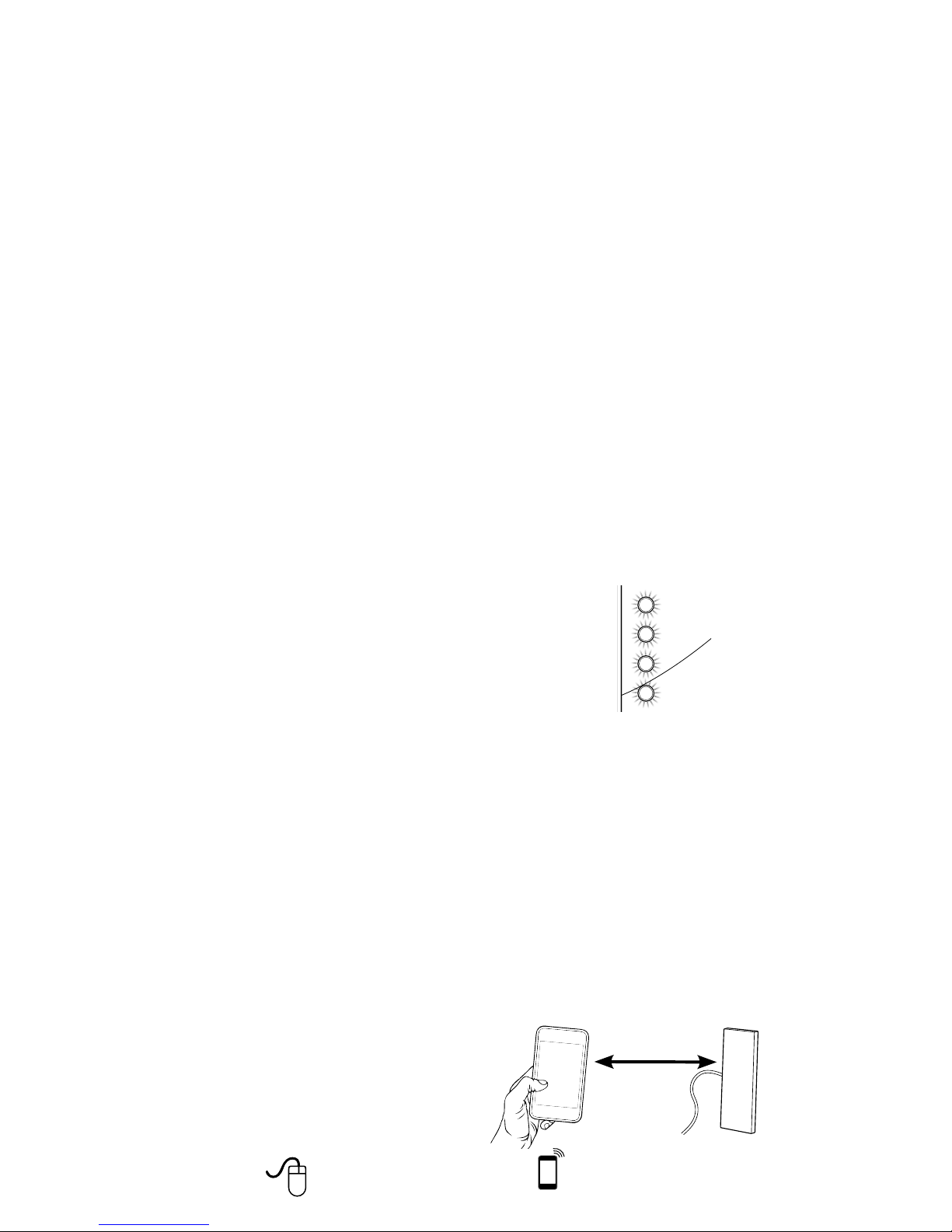
Red light: A red light indicates oscillation
is occurring. Oscillation is similar to
feedback between a microphone and
speaker. When oscillation occurs, the
Signal Booster will power down to protect
the cell tower. To eliminate oscillation,
the outside antenna needs to be moved
farther from the inside antenna. Move the
outside antenna on the roof to the rear of
the car, but at least 8 to 12 inches from
the rear or side windows. Disconnect
the power from the Signal Booster, then
reconnect the power to reset the Signal
Booster.
Blinking Red/Green: If one or more
of the lights on the Signal Booster are
blinking red/green, this means that the
Signal Booster has reduced gain due
to oscillation. Increase the distance
between the Outside and the Inside
Antennas, or place the Outside Antenna
near the center of the vehicle, and reset
the Signal Booster by disconnecting then
reconnecting the power to the signal
booster. Contact Wilson Electronics
Technical Support Team for assistance.
Increase
distance
Inside
antenna
• Power up your Signal Booster by
ipping the switch on the back of the
DC power adapter on. A red light
should appear on the power adapter.
Note: The Mobile 4G Signal Booster
may remain on, in vehicles whose
12V DC power sources do not
automatically shutdown when the
vehicle is turned off. This could
result in discharging the vehicles
battery in one to two days.
Note: Some 12V DC power sources
are shut down when the vehicle
ignition is turned to off. Refer to
your vehicle owners manual for
specics related to your vehicle.
NOTE: The aluminum casing of
your Signal Booster will adjust to the
temperature of its environment, but is
designed to protect the Signal Booster
technology. For example, in the summer,
the Signal Booster case may be as hot
as 150 degrees inside your vehicle.
These high temperatures will NOT
damage the Signal Booster, nor do they
pose a re risk to the vehicle. Again, be
sure to place your Signal Booster in a
location with adequate ventilation and
away from direct sunlight or moisture.
Troubleshooting &
Understanding Lights
The lights on the front of the Mobile
4G Signal Booster indicate whether
the system is working or if there are
problems. Each light indicates the
operation of its labeled frequency. Take
the following steps based on the indicator
light color when using the Mobile 4G
Signal Booster.
Lights off: If the lights are not on:
• Check connections on the power
supply to see that it is rmly plugged
Page 6
6
Need help? www.WilsonElectronics.com
Tech Support 866-294-1660
Mon.- Fri. Hours: 7 am to 6 pm MST
Green light: A green light indicates the
Mobile 4G Signal Booster is working
properly.
If you have additional questions about
the operation of your Mobile 4G Signal
Booster, please contact the Wilson
Electronics technical support team
at 866-294-1660 or email tech@
wilsonelectronics.com.
Additional FAQ:
What hours can I contact tech support?
Technical Support can be reached
from 7:00am to 6:00pm MST, by calling
(866-294-1660), or by email, at tech@
wilsonelectronics.com
How does weather affect the
performance of my outside antenna?
Water vapor (e.g. rain, fog, snow or
other precipitation) creates an effective
lter to cellular signal. In times of
heavy precipitation, you may see less
performance.
What’s the difference between the 800
MHz and the 1900 MHz bands? How do
I know which MHz band my cell phone
uses?
The Mobile 4G works with all major North
American cellular providers on the 800
& 1900 MHz frequencies. Traditionally,
800/1900MHz are associated with voice and
3G data; while 700MHz and 1700/2100MHz
are associated with 4G data.
Carrier Frequency Use
We recommend visiting wirelessadvisor.
com (US) or http://bit.ly/1mQf2Gl (Canada)
for information regarding the frequency
band used by your cell service provider in a
specic geographical location.
Kit 301121-40010
• 50 Ohm Dome Antenna
• 10’ LMR400
Kit 311135-40060
• 50 Ohm Wall Panel Antenna
• 60’ LMR400
Kit 301151-0610
• 75 Ohm Dome Antenna
• 10’ RG6 Cable
Kit 311135-5820
• 50 Ohm Wall mount Panel Antenna
• 20’ RG58 Cable
Kit 311135-40060
• 50 Ohm Wall Mount Panel Antenna
• 60’ LMR400 Cable
Kit 301151-1110
• 75 Ohm Dome Antenna
• 10’ RG11 cable
Kit 311155-1150
• 75 Ohm Wall mount Panel Antenna
• 50’ RG11 Cable
Kit 301211
• Desktop Antenna w/ 5’ RG174
50 Ohm Outside Antenna Kits
Kit 314453-5825
• 50 Ohm Pole Mount Panel Antenna
• 25’ RG58 Cable
Inside Antenna Kits
Kit 309900-50N
• 2 - Wall Panel antennas
• 1 - 50 ohm 3-Way Splitter
Kit 309905-50N
• 3 - Wall Panel Antennas
• 3 - 2-Way 50 Ohm Splitters
Kit 309902-75F
• 2 - Wall Panel Antennas
• 1 - 3-Way 75Ohm Splitter
Kit 309903-75F
• 3 - Wall Panel Antennas
• 3 - 2-Way 75Ohm Splitters
Kit 309904-75F
• 1 - Wall Panel Antenna
• 1 - 2-Way 75 Ohm Splitter
Inside Antenna Expansion Kit
Page 7

7
Need help? www.WilsonElectronics.com
Tech Support 866-294-1660
Mon.- Fri. Hours: 7 am to 6 pm MST
Kit 311129-0650
• 1900 MHz Yagi Directional
• 50’ RG6 Cable
• N-Male to F-Female adapter
Kit 314473-0640
• 75 Ohm Pole Mount Panel Antenna
• 40’ RG6 Cable
Kit 311141-0620
• 75 Ohm Grey Brick Antenna
• 20’ RG6 Cable
Kit 301111-11140
• Yagi Directional Antenna
• 140’ RG11 Cable
• N-Male to F-Female adapter
Kit 311201-1120
• Omni Directional w/ F-Female
• 20’ RG11 Cable
Kit 311129-11110
• 800 MHz Yagi Directional
• 110’ RG11 Cable
• N-Male to F-Female adapter
Kit 311124-1180
• 1900 MHz Yagi Directional
• 80’ RG11 Cable
• N-Male to F-Female adapter
Kit 314473-1175
• 75 Ohm Pole Mount Panel Antenna
• 75’ RG11 Cable
Kit 314475-0630
• 75 Ohm Wide Band Directional
• 30’ RG6 Cable
Kit 314475-1175
• 75 Ohm Wide Band Directional
• 75’ RG11 Cable
Kit 311141-1120
• 75 Ohm Grey Brick Antenna
• 20’ RG11 Cable
Kit CANT-0040
• Omni Antenna
• 50’ RG6 cable
Kit CANT-0043
• Panel Antenna
• 50’ RG6 cable
Kit CANT-0042
• Wide Band Directional Antenna
• 60’ RG6 cable
Kit 314411-5825
• 50 Ohm Wide Band Directional
• 25’ RG58 Cable
Kit 301111-5850
• Yagi Directional Antenna
• 50’ RG58 Cable
Kit 311129-5840
• 8000 MHz Yagi Directional
• 40’ RG58 Cable
Kit 311203-5820
• Omni-Directional antenna
• 20’ RG58 Cable
Kit 311124-5830
• 1900 MHz Yagi Antenna
• 30’ RG58 Cable
Kit 311203-40020
• Omni-Directional antenna
• 20’ LMR400 Cable
Kit 301111-400170
• Yagi Directional w/ N-Female
• 170’ LMR400
Kit 311124-400100
• 1900 MHz Yagi Directional
• 100’ LMR400 Cable
Kit 311129-400100
• 800 MHz Yagi Antenna
• 100’ LMR400 Cable
Kit 314411-40075
• 50 Ohm Wide Band Directional Antenna
• 75’ LMR400 Cable
Kit 314453-40075
• 50 Ohm Pole Mount Panel Antenna
• 75’ LMR400 Cable
Mini-Mag 301126 w/12.5 RG174 cable-SMA
75 Ohm Outside Antenna Kits
Kit 301111-0675
• Yagi Directional Antenna
• 75’ RG6 Cable
• N-Male to F-Female adapter
Kit 311201-0620
• Omni Antenna w/ F-Female
• 20’ RG6 Cable
Kit 311129-0660
• 800 MHz Yagi Directional
• 60’ RG6 Cable
• N-Male to F-Female adapter
Page 8
8
Need help? www.WilsonElectronics.com
Tech Support 866-294-1660
Mon.- Fri. Hours: 7 am to 6 pm MST
Safety Guidelines
WARNING: The inside panel and dome antennas must have 6’ of separation distance from all active users,
and the low profile antennas must have 18” of separation distance from all active users.
WARNING: Connecting the Signal Booster directly to the cell phone with use of an adapter will damage the
cell phone.
WARNING: Use only the power supply provided in this package. Use of a non-Wilson Electronics product
may damage your equipment.
WARNING: The Signal Booster unit is designed for use in an indoor, temperature-controlled environment
(less than 150 degrees Fahrenheit). It is not intended for use in attics, vehicles or similar locations
subject to temperatures in excess of that range.
WARNING: The Outside Antenna must be installed no higher than 10 meters (32’9”) above ground.
RF SAFETY WARNING: Any antenna used with this device must be located at least 8 inches from all persons.
BEFORE USE, you MUST REGISTER THIS DEVICE with your wireless provider and have your
provider’s consent. Most wireless providers consent to the use of signal boosters. Some providers
may not consent to the use of this device on their network. If you are unsure, contact your provider.
You MUST operate this device with approved antennas and cables as specified by the manufacturer.
Antennas MUST be installed at least 20 cm (8 inches) from any person.
You MUST cease operating this device immediately if requested by the FCC or a licensed wireless
service provider.
WARNING. E911 location information may not be provided or may be inaccurate for calls served by
using this device.
This is a CONSUMER device.
Mobile Antennas
Mini-Mag
• 301126 w/ 12.5 RG174 cable- SMA
• 301113 w/ 12.5 RG174 cable- FME
12” Mag Mount w/ 12.5’ RG174
• 311103
• 311125
• 311128
• 311703
Trucker antenna w/10.5’ RG58
• 311101
• 311701
Trucker antenna w/13.5’ RG58
• 311119
• 311133
NMO Antenna’s w/ RG174
Kit 311104-17410
• 800/1900 NMO antenna
• 10’ RG174 cable
Kit 311112-17410
• 800/1900 NMO antenna
• 10’ RG174 cable
Kit 314203-17410
• 800/900/1900 NMO antenna
• 10’ RG174 cable
NMO Antenna’s w/ RG174
Kit 311130-5810
• Marine Antenna
• 10’ RG58 cable
Glass Mount w/14’ RG58 cable
• 311102
• 311114 ( Mini Glass Mount)
NMO Antenna’s w/ RG58
Kit 311104-5810
• 800/1900 NMO antenna
• 10’ RG58 cable
Kit 311112-5810
• 800/1900 NMO antenna
• 10’ RG58 cable
Kit 314203-5810
• 800/900/1900 NMO antenna
• 10’ RG58 cable
Page 9
9
Need help? www.WilsonElectronics.com
Tech Support 866-294-1660
Mon.- Fri. Hours: 7 am to 6 pm MST
Signal Booster Specifications
Mobile 4G
Model Number 460021
Connectors SMA
Antenna Impedance 50 Ohms
Frequency 698-716 MHz, 746-787 MHz, 824-894 MHz, 1850-1995 MHz, 1710-1755/2110-2155 MHz
Passband Gain (typical)
700 MHz Band 12/17
45.8
700 MHz Band 13
46.8
800 MHz
46.8
1700/2100 MHz
45.2
1900 MHz
44.6
20 dB Bandwidth (MHz)
700 MHz Band 12/17 700 MHz Band13 800 MHz 1700/2100 MHz 1900 MHz
Typical
Maximum
30.6
35.2
31.0
35.2
37.9
39.9
79.2
79.8
77.3
83.2
Power output for single cell
phone (Uplink) dBm
700 MHz Band 12/17 700 MHz Band13 800 MHz 1700 MHz 1900 MHz
24.84 24.35 23.4 21.3 24.43
Power output for single cell
phone (Downlink) dBm
700 MHz Band 12/17 700 MHz Band13 800 MHz 2100 MHz 1900 MHz
2.87 2.79 2.8 2.0 1.92
Power output for multiple
received channels
(Uplink) dBm
No. Tones
Maximum Power
700 MHz Band12/17 700 MHz Band13 800 MHz 1700 MHz 1900 MHz
2 25.4 23.9 22.9 22.8 24.9
3 21.8 20.4 19.4 19.3 21.3
4 19.3 17.9 16.9 16.8 18.8
5 17.4 16.0 15.0 14.8 16.9
6 15.8 14.4 13.4 13.2 15.3
Power output for multiple
received channels
(Downlinklink) dBm
Maximum Power
No. Tones 700 MHz Band12/17 700 MHz Band13 800 MHz 2100 MHz 1900 MHz
2 4.8 5.6 5.4 6.3 4.5
3 1.3 2.1 1.9 2.8 0.9
4 -1.2 -0.4 -0.6 0.3 -1.6
5 -3.2 -2.4 -2.6 -1.6 -3.5
6 -4.7 -4.0 -4.2 -3.2 -5.1
Noise Figure 5 dB nominal
Isolation > 90 dB
Power Requirements
5 V 2.5 A
Each Signal Booster is individually tested and factory set to ensure FCC compliance. The Signal Booster cannot be adjusted without factory
reprogramming or disabling the hardware. The Signal Booster will amplify, but not alter incoming and outgoing signals in order to increase coverage
of authorized frequency bands only. If the Signal Booster is not in use for five minutes, it will reduce gain until a signal is detected. If a detected
signal is too high in a frequency band, or if the Signal Booster detects an oscillation, the Signal Booster will automatically turn the power off on
that band. For a detected oscillation the Signal Booster will automatically resume normal operation after a minimum of 1 minute. After 5 (five) such
automatic restarts, any problematic bands are permanently shut off until the Signal Booster has been manually restarted by momentarily removing
power from the Signal Booster. Noise power, gain, and linearity are maintained by the Signal Booster’s microprocessor.
The Manufacturer’s rated output power of this equipment is for single carrier operation. For situations when multiple carrier signals are present, the
rating would have to be reduced by 3.5 dB, especially where the output signal is re-radiated and can cause interference to adjacent band users.
This power reduction is to be by means of input power or gain reduction and not by an attenuator at the output of the device.
This device complies with Part 15 of FCC rules. Operation is subject to two conditions: (1) This device may not cause harmful interference, and
(2) this device must accept any interference received, including interference that may cause undesired operation. Changes or modifications not
expressly approved by Wilson Electronics could void the authority to operate this equipment.
Page 10
3301 East Deseret Drive, St. George, UT 84790
web: www.WilsonElectronics.com email: [email protected]
phone: 866-294-1660 local: 435-673-5021 fax: 435-656-2432
30-Day Money-Back Guarantee
All Wilson Electronics products are protected by Wilson Electronics 30-day money-back guarantee. If
for any reason the performance of any product is not acceptable, simply return the product directly to the
reseller with a dated proof of purchase.
2-Year Warranty
Wilson Electronics Signal Boosters are warranted for two (2) years against defects in workmanship and/or
materials. Warranty cases may be resolved by returning the product directly to the reseller with a dated proof of
purchase.
Signal Boosters may also be returned directly to the manufacturer at the consumer’s expense, with a dated
proof of purchase and a Returned Material Authorization (RMA) number supplied by Wilson Electronics. Wilson
Electronics shall, at its option, either repair or replace the product. Wilson Electronics will pay for delivery of the
repaired or replaced product back to the original consumer if located within the continental U.S.
This warranty does not apply to any Signal Boosters determined by Wilson Electronics to have been subjected to
misuse, abuse, neglect, or mishandling that alters or damages physical or electronic properties.
Failure to use a surge protected AC Power Strip with at least a 1000 Joule rating will void your warranty.
RMA numbers may be obtained by contacting Technical Support at 866-294-1660.
Disclaimer: The information provided by Wilson Electronics, LLC is believed to be complete and accurate. However, no
responsibility is assumed by Wilson Electronics, LLC for any business or personal losses arising from its use,
or for any infringements of patents or other rights of third parties that may result from its use.
Copyright © 2014 Wilson Electronics, LLC All rights reserved.
U.S. Patent Nos. – 7,221,967; 7,729,669; 7,486,929; 7,409,186; 7,783,318; 8,583,034; 8,583,033; 8,639,180
111285_Erin_RevP_10.29.14
 Loading...