

Page 1

Antenna
Installation
Guide
Features:
• High-gain
• Directional
• Pipe mounting hardware included
• Easy to install
• Weather resistant
• Wide bandwidth
700 MHz - 2700 MHz
Wide Band Directional Antenna
PART# 304411
308412
Disclaimer: The information provided by Wilson Electronics, Inc. is believed to
be complete and accurate. However, no responsibility is assumed by Wilson
Electronics, Inc. for any business or personal losses arising from its use, or for any
infringements of patents or other rights of third parties that may result from its use.
Copyright © 2010 Wilson Electronics, Inc. All rights reserved.
304475
Page 2
1
2
How It Works
Wilson Electronics Wide Band Log Periodic Directional Antenna will collect the cell tower
signal and send it through the cable to a signal booster, cell phone or cellular data card.
When the cell phone or cellular data card transmits, the signal is transferred to a signal
booster or directly to the antenna and broadcast back to the cell tower.
Package Contents
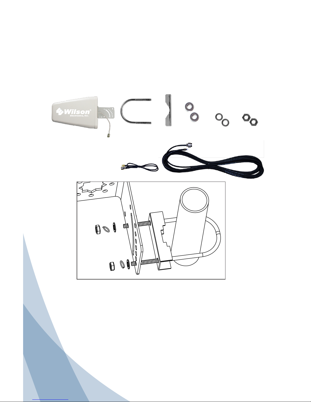
(A) Wide Band Log Periodic Directional Antenna & L Bracket, (B) 2 - U-Bolts, (C) 2 - Pipe
Brackets, (D) 4 - 1/4” Washers ,(E) 4 - 1/4” Split-Lock Washers, (F) 4 - 1/4”-20 nuts.
• 359933, 20” RG174 Cable with
FME male to MCX Connector.
• 951137, 30” RG58 Cable.
308412 additional kit contents:
A B EC F
D
1 – Install U-Bolt (B) on pole.
2 – Slide Pipe Clamp (C) over U-Bolt (B) Flat side away from pipe.
3 – Slide antenna bracket (A) onto U-Bolt (B) in desired location.
4 – Install Flat washer (D), split lock washer (E) and nut (F), tighten as appropriate.
Note: Antenna may be installed on a variety of pipe angles, insure antenna is
pointing at cell tower and is vertical with the drip hole at the bottom.
Note: A second U-Bolt assembly has been included to strengthen antenna mounting
in windy areas repeat steps 1 thru 4 to install.
Antenna Mounting Instructions
Contact Wilson Electronics Technical Support Team with any questions at 866-294-1660
or email: [email protected]. Hours: 7 am to 6 pm MST.
Page 3
2
Antenna Installation
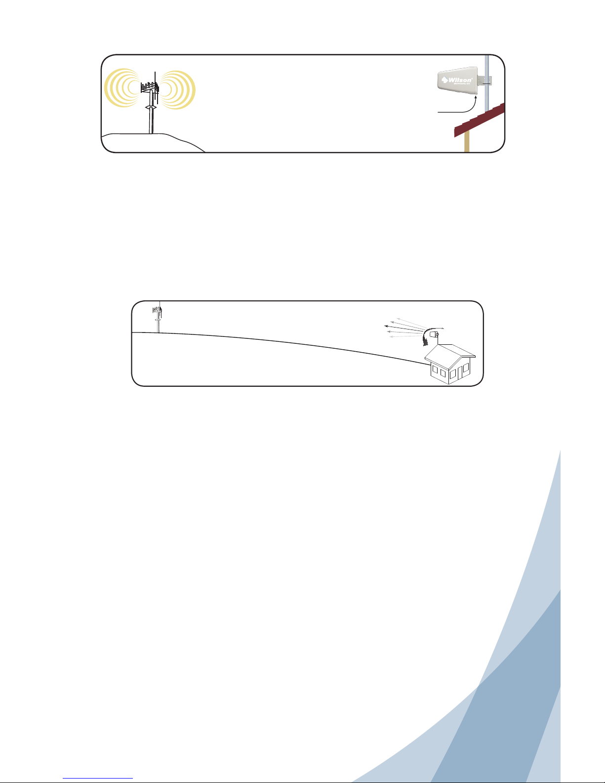
The antenna should be mounted as shown in the illustration above. The included
mounting bracket is adjustable and will accommodate pipe diameters from 1.25” to 2”
(pipe not included). Mount the antenna so that there is at least 3 feet of clearance in all
directions around it. Position the antenna so that it has the most unobstructed line of
sight to the cellular service provider’s strongest signal. If you are using a wireless signal
booster, make sure the antenna is not pointing across your own roof.
Warning: Lightning protection is recommended for all installations (Wilson
Electronics Part #859902). Take extreme care to ensure that neither you nor the
antenna comes near any electric power lines.
Cell Tower
RF Signal
Wide Band
Antenna
Adjusting the Antenna for Maximum Performance
To adjust the antenna for best performance, connect it to your cell phone with an external
adapter and a length of coaxial cable. External antenna adapters and coaxial cables
are sold separately. Put the cell phone in test mode and turn the Antenna in 10-degree
increments while checking the cell phone’s signal level. At each point you may need to
wait a few seconds as your cell phone updates. To find your phone’s test mode, visit
www.wilsonelectronics.com. Signal readings usually appear as a negative number (for
example, -86). The larger the number, the more powerful the signal (-75 is stronger than
-84).
Antenna Adapter
An 18-inch external adapter may be required to connect the cell phone or cellular data
card directly to the antenna. The external adapter is cell phone/data card specific and
may be purchased through a local retailer. Refer to Wilson Electronics Adapter Guide
to identify the right adapter for your cell phone or cellular data card. The Adapter
Guide is available through a local retailer. It is also available on our web site, www.
wilsonelectronics.com, or you may call Technical Support at 866-294-1660.
Cell Tower
Drip hole on bottom
signal loss. Wilson Electronics offers cable in several lengths from 20-1000 feet.
Wilson Electronics also offers a wide range of phone adapters to connect your cell
phone, to a signal booster, or directly to the antenna.
Important: If you are using a wireless signal booster, be sure the Antenna is not
pointing across the building in which you are trying to get coverage. The antenna
should point away from the building to help prevent oscillation (feedback).
Once you have obtained the strongest signal, fully tighten the mounting hardware.
Ultra low loss coax is recommended for lengths 20’ or greater to prevent significant
Contact Wilson Electronics Technical Support Team with any questions at 866-294-1660
or email: [email protected]. Hours: 7 am to 6 pm MST.
Page 4
Part #104100 AIG Wide Band Log Periodic Rev11 11.29.10
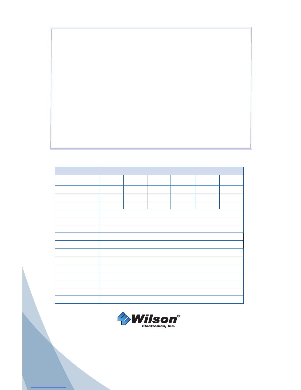
Antenna Specifications
Part Number 50 Ω - 304411 • 75 Ω - 304475
Frequency Range
700 -800
MHz
800-915
MHz
915-1710
MHz
1710-1850
MHz
1850-1990
MHz
1990-2700
MHz
Gain 8.0 dBi 8.0 dBi 7.0 dBi 9.0 dBi 10.5 dBi 10.0 dBi
50 Ω VSWR avg. 1.6:1 1.4:1 1.3:1 1.2:1 1.2:1 1.2:1
75 Ω VSWR avg. 1.5:1 1.3:1 1.6:1 2.0:1 1.7:1 1.5:1
Horizontal Beamwidth 70° to 90°
Vertical Beamwidth 85° to 110°
F/B ratio >20 dB
Nominal Impedance 50 Ω - 304411 • 75 Ω - 304475
Polarization Vertical
Maximum Power 100 watts
Connector 50 Ω - N-Female • 75 Ω - F-Female
Dimension 11.42” x 8.27” x 2.56” In
Weight 3.31 lbs
Temperature Range -40° to 158° F
Rated Wind Velocity 134 MPH
Lightning Protection DC grounded
30-Day Money-Back Guarantee
All Wilson Electronics products are protected by Wilson Electronics 30-day money-back
guarantee. If for any reason the performance of any product is not acceptable, simply return the
product directly to the reseller with a dated proof of purchase.
90-Day Warranty
Wilson Electronics antennas are warranted for ninety (90) days against defects in workmanship
and / or materials. Warranty cases may be resolved by returning the product directly to the
reseller with a dated proof of purchase.
Antennas may also be returned directly to the manufacturer at the consumer’s expense, with
a dated proof of purchase and a Returned Material Authorization (RMA) number supplied by
Wilson Electronics. Wilson Electronics shall, at its option, either repair or replace the product.
Wilson Electronics will pay for delivery of the repaired or replaced product back to the original
consumer with in the continental U.S.
This warranty does not apply to any signal boosters determined by Wilson Electronics to have
been subjected to misuse, abuse, neglect, or mishandling that alters or damages physical or
electronic properties.
RMA numbers may be obtained by phoning Technical Support at 866-294-1660.
3301 East Deseret Drive, St. George UT 84790
For additional Technical Support visit www.wilsonelectronics.com
or email at: [email protected]
Phone: 866-294-1660 Local: 435-673-5021 Fax: 435-656-2432
www.twitter.com/WilsonCellular www.facebook.com/WilsonCellular
 Loading...