

Page 1

Antenna
Installation
Guide
Features:
• Multi-band
• Analog and digital
• Improves voice and data signal quality
• Designed for RV’s and trucks
• Built-in spring reduces impact damage
• Built-in ground plane allows for mounting on any surface
RV / Trucker
Roof Mount
Cellular Antenna
PART# 301119
Page 2
1
Contact Wilson Electronics Technical Support Team with any questions at 866-294-1660
or email: [email protected]. Hours: 7 am to 6 pm MST.
2
How It Works
Wilson Electronics RV / Trucker Roof Mount Cellular Antenna will collect the cell tower
signal and send it through the cable to a signal booster or directly to the cell phone or
laptop data card. When the cellular device transmits, the signal is transferred to a signal
booster or directly to the antenna and broadcasted back to the cell tower.
Antenna Adapter Required – Sold Separately
A phone/data card-specific, six-inch Antenna Adapter is required when connecting
the antenna directly to a cellular device. To identify the correct adapter, see Wilson
Electronics Adapter Guide at www.WilsonElectronics.com or call Technical Support at
866-294-1660.
Adapter type may vary depending on
your cell phone or laptop data card.
Package Contents
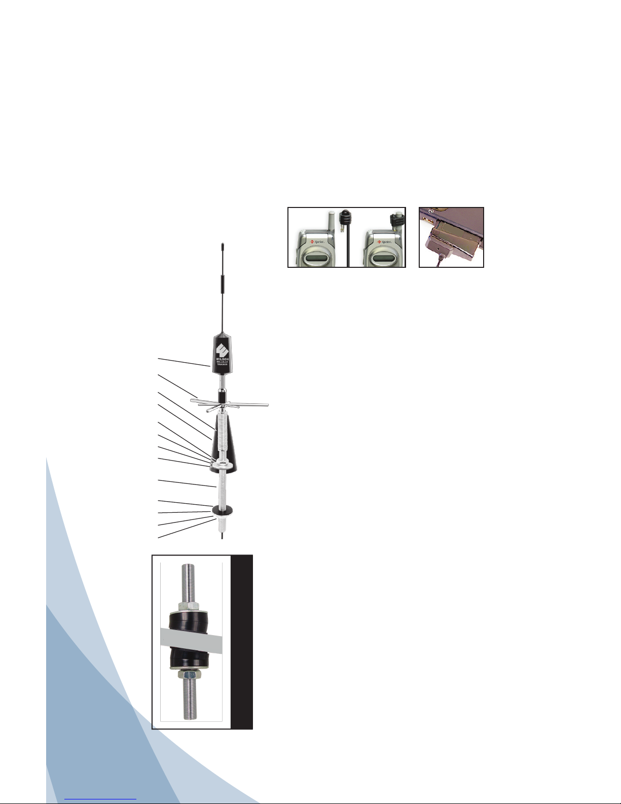
1 - RV / Trucker Antenna 2 - 5/8” nuts
6 - radials (3 short, 3 long) 2 - star lock washers
1 - thread-locker liquid 2 - steel washers
2 - rubber washers 1 - rubber boot
2 - sets of angle mounts 1 - 5/8” x 7” threaded rod
Installing the Antenna
1. Unscrew the 7” threaded rod from the antenna and
slide it off the antenna cable. Remove the washers
and nuts from the threaded rod. Leave the rubber boot
on the antenna.
2. Choose the location to mount your antenna. Some
installations may require headliner removal - this is
difficult and my require a professional installer. For
RV’s we recommend mounting your antenna so that
the lower hole is hidden inside a cabinet towards
the front of the RV. If you are installing on a slanted
surface, you will want to use the included angle
mounts (see Diagram 1). If you use the angle mounts,
make sure the rubber washers are placed directly against
the mounting surface.
3. Disconnect the vehicle’s electrical power. Drill a 5/8”
hole up through the roof being careful not to come into
contact with electrical wires or air vents. Drill the hole
perpendicular to the ground. Avoid following any slant
in the roof. (Antenna should be mounted vertically).
4. Note that one end of the threaded rod has inside
threads. This is the top end that the antenna will screw
into after installation of the threaded rod. Put a rubber
washer, angle mount (if mounting surface is slanted),
steel washer, star washer and nut on top of the
threaded rod. Push the threaded rod down through
the hole - the side that has inside threads must be on
top. If you are mounting on a slanted surface, rotate
the angle mounts to account for any gaps.
RV/Trucker
Cellular Antenna
Radials
Spring
Rubber Boot
5/8” Nut
Star Washer
Steel Washer
Rubber Washer
5/8” x 7”
Threaded rod
Rubber Washer
Steel Washer
Star Washer
5/8” Nut
DIAGRAM 1 (Angle Mounts)
ANGLED ROOF
Page 3
2
Contact Wilson Electronics Technical Support Team with any questions at 866-294-1660
or email: [email protected]. Hours: 7 am to 6 pm MST.
Disclaimer: The information provided by Wilson Electronics, Inc. is believed
to be complete and accurate. However, no responsibility is assumed by Wilson
Electronics, Inc. for any business or personal losses arising from its use, or for
any infringements of patents or other rights of third parties that may result from
its use.
Copyright © 2011 Wilson Electronics, Inc. All rights reserved.
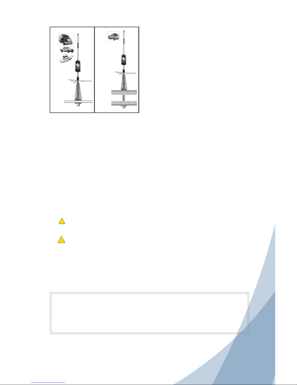
Roof
Ceiling
Roof
Headliner
5. Depending on your application, you may want to
cut the threaded rod if it extends too far down from
the roof. Alternatively, if the ceiling of your vehicle
is thicker than 7 inches, Wilson Electronics offers
a 12-inch threaded rod (part #901116), available
through your dealer. If you don’t want to cut - skip
to step 6. The threaded rod is brass and should cut
easily. Mark the location of the cut on the lower part
of the threaded rod. Leave enough threads to fit the
remaining three washers and the nut. Remove the
threaded rod from the vehicle. Place a nut onto the
threaded rod at the point where you will cut it.
CAUTION: Check that you are not cutting into the
top end with the inside threads. Tighten this nut
in a vise and cut with a hacksaw. Once the cut is
complete, remove the nut from the cut end to deburr the threads. Use a rat-tail file or knife to deburr the inside of the rod. This is important because
a sharp edge may later cut the cable.
6. Push the threaded rod back down through the hole in the roof. Place a rubber washer, steel washer,
star washer and nut onto the lower end of the threaded rod. Tighten the nut until it is snug, but do not
over tighten. It may be necessary to have a second person hold the nut on top of the vehicle.
7. Feed the antenna’s cable through the center of the threaded rod from the top of the vehicle. Screw
the bottom of the antenna to the internal threads of the threaded rod. We recommend that you place
a bead of silicone caulking around the outside rubber washer and bottom of the outside nut. Push the
rubber boot down over the nut and washers.
8. The six radials should be screwed into the antenna just above the short fiberglass rod. A small amount
of the included liquid thread lock on the radial’s threads will ensure that they will not vibrate out.
9. Route the cable to the location where you will be using your phone. Attach the adapter (not included)
to the female FME connector on the end of the antenna cable.
NOTE: For best performance, it is important to mount the antenna as high as possible.
Warning: If using a signal booster, ensure that all antenna and adapter cables are
connected before powering up the signal booster.
!
Warning: Mount the antenna at least 8 inches away from any other antennas to avoid
interference.
!
Technical Support
You may obtain additional help by calling 1-866-294-1660, Monday through Friday between 7:00 AM
and 6:00 PM MST.
Page 4
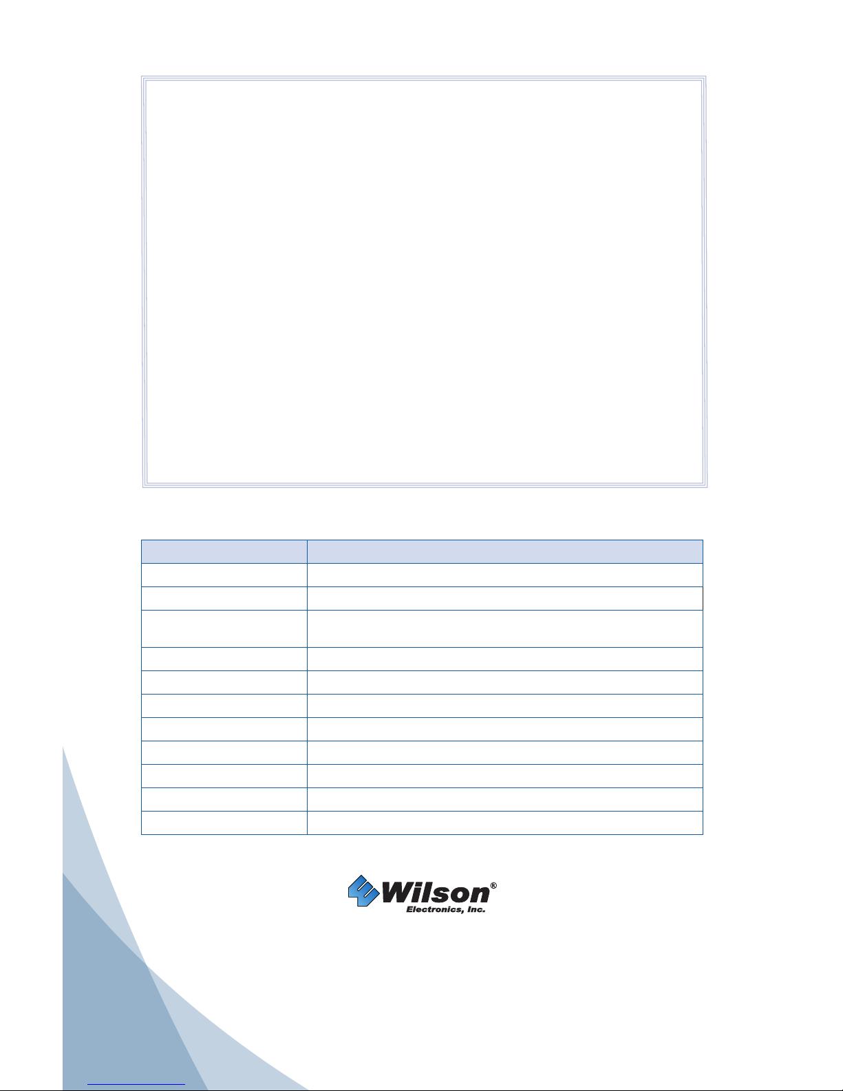
Antenna Specifications
Part Number 301119
Frequency Range 700-800 MHz / 824-894 MHz / 880-960 MHz /1850-1990 MHz
Impedance 50 ohms
Antenna Gain
3.1 dBi 700-800 MHz / 4.1 dBi 824-894 MHz /
2.0 dBi 880-960 MHz / 5.1 dBi 1850-1990 MHz
Radiation Omni
Polarization Vertical
Ground Plane Built-in Ground Plane
Connector FME Female
Material Whip - Stainless Steel
Coax Cable RG58 - 13.5 feet / 4.115 meters
Height 24 inches including threaded mount / 45.72 cm
Mount 5/8” x 7” threaded mounting rod
30-Day Money-Back Guarantee
All Wilson Electronics products are protected by Wilson Electronics 30-day
money-back guarantee. If for any reason the performance of any product is not
acceptable, simply return the product directly to the reseller with a dated proof of
purchase.
1-Year Warranty
Wilson Electronics Trucker Roof-Mount Multi-Band Cellular Antenna is warranted
for one (1) year against defects in workmanship and/or materials. Warranty cases
may be resolved by returning the product directly to the reseller with a dated proof
of purchase.
Antennas may also be returned directly to the manufacturer at the consumer’s
expense, with a dated proof of purchase and a Returned Material Authorization
(RMA) number supplied by Wilson Electronics. Wilson Electronics shall, at its
option, either repair or replace the product. Wilson Electronics will pay for delivery
of the repaired or replaced product back to the original consumer.
This warranty does not apply to any antennas determined by Wilson Electronics
to have been subjected to misuse, abuse, neglect, or mishandling that alters or
damages physical or electronic properties.
RMA numbers may be obtained by phoning Technical Support at 866-294-1660 or
e-mail [email protected].
3301 East Deseret Drive, St. George, UT 84790
For additional Technical Support visit www.WilsonElectronics.com
or email at: [email protected]
Phone: 866-294-1660 Local: 435-673-5021 Fax: 435-656-2432
www.twitter.com/WilsonCellular www.facebook.com/WilsonCellular
Part #103016 AIG RRV T 008 / 0 6.06.11
 Loading...