

Wilson Electronics 273470 Installation Manual

Contents:
Antenna Options & Accessories . . . . . . . . . . . . . . . . . . . . . . . . . . . . . . . . . . . .1
Quick Install Overview . . . . . . . . . . . . . . . . . . . . . . . . . . . . . . . . . . . . . . . . . . . .2
Installation Diagram . . . . . . . . . . . . . . . . . . . . . . . . . . . . . . . . . . . . . . . . . . . . . .3
Before Getting Started . . . . . . . . . . . . . . . . . . . . . . . . . . . . . . . . . . . . . . . . . . . .4
Installing the Outside Antenna . . . . . . . . . . . . . . . . . . . . . . . . . . . . . . . . . . . . . .5
Finding the Strongest Signal . . . . . . . . . . . . . . . . . . . . . . . . . . . . . . . . . . . . . . .6
Installing the Inside Antenna . . . . . . . . . . . . . . . . . . . . . . . . . . . . . . . . . . . . . . .8
Installing a Wilson Electronics Signal Booster. . . . . . . . . . . . . . . . . . . . . . . . . .9
Powering up a Wilson Electronics Signal Booster . . . . . . . . . . . . . . . . . . . . . . . 9
Understanding the Signal Booster Lights . . . . . . . . . . . . . . . . . . . . . . . . . . . . 10
Warnings and Recommendations . . . . . . . . . . . . . . . . . . . . . . . . . . . . . . . . . .12
Guarantee & Warranty . . . . . . . . . . . . . . . . . . . . . . . . . . . . . . . . . . . . . . . . . . .14
Specifications . . . . . . . . . . . . . . . . . . . . . . . . . . . . . . . . . . . . . . . . . Back Cover
Note: This manual contains important safety and operating information. Please read and follow the instructions
in this manual. Failure to do so could be hazardous and result in damage to your Signal Booster.
AG Pro Quint
Appearance of device and accessories may vary.
700 / 800 / AWS (1700 / 2100) / 1900 MHz
In-Building Wireless
Smart Technology ™
Signal Booster
1
Contact Wilson Electronics Technical Support Team with any questions at 866-294-1660
or email: tech@wilsonelectronics.com. Mon.- Fri. Hours: 7 am to 6 pm MST.
Installation Instructions for the Following
Wilson Electronics Signal Boosters:
How it Works
Designed for professional installation to provide signal coverage in buildings up to 80,000
square feet. The Wilson AG Pro Quint boosts signals on 800 MHz, 1900MHz, AWS and both
AT&T and Verizon 700 MHz 4G networks as well as Sprint 4G on the G-Block of 1900 MHz.
The AG Pro Quint is the most affordable five-band Signal Booster available. Wilson’s compact,
integrated design is about the size of a textbook and weighs less than 3 pounds. The AG Pro
Quint’s control knobs allow the installer to optimize the gain on each of the frequency bands.
The AG Pro Quint delivers up to 75 dB of gain and supports CDMA, GSM, EVDO, LTE, HSPA+
and WCDMA technologies. It can be paired with an Outside Directional Antennas and a variety
of Wilson Inside Antennas to create a custom Signal Booster system. Like all Wilson Signal
Boosters this unit features cell tower protection technologies refined over more than a decade
of research and development.
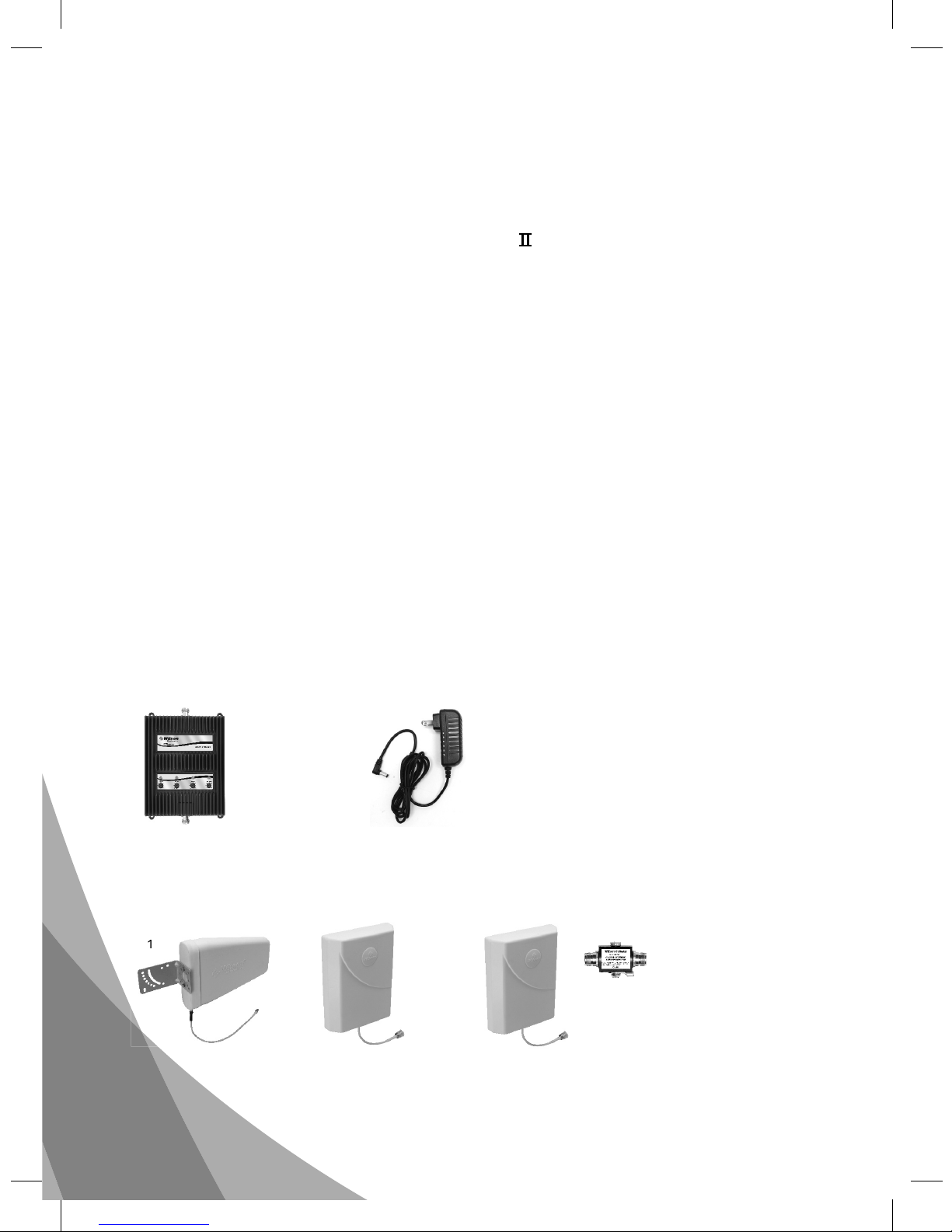
Inside this Package
Signal
Booster
To purchase, contact Wilson Electronics Sales Department at: 800-204-4104
Outdoor Antenna Options
Indoor Antenna Options & Accessories
1. Wide Band Directional Antenna 700 MHz 2700 MHz (304411)
2. Pole Mount Panel Antenna (304453)
A. Wide-Band Panel Antenna 700-2700MHz
(multiple mounting options available)
B. 50 Ohm Lightning Surge Protector N-Connector (859902)
12
B
A
12V / 3A
AC/DC
Power
Supply
(859900)
Note: Kits may contain different accessories
Appearance of device and accessories may vary.
AG Pro™ Quint
700 / 800 / AWS (1700 / 2100) / 1900 MHz
In-Building Wireless Smart Technology ™ Signal Booster
PN # 803670 Model # 273470 FCC ID: PWO273470
The term “IC” before the radio certification number only signifies that Industry Canada technical
specifications were met.

2
Contact Wilson Electronics Technical Support Team with any questions at 866-294-1660
or email: tech@wilsonelectronics.com. Mon.- Fri. Hours: 7 am to 6 pm MST.
1. Select a location to install the Signal Booster that is away from excessive heat,
direct sunlight, moisture and has proper ventilation. Do not place the Signal
Booster in an air-tight enclosure.
2. Select a location on the roof of the building to install the Outside Antenna. Use
a cell phone in test mode to find the strongest signal from the cell tower (refer
to page 6). Visit www.WilsonElectronics.com to find test mode function for your
particular cell phone.
3. Run the Outside Antenna cable to the Signal Booster and attach it to the
connector labeled “Outside Antenna” on the Signal Booster. Run the Inside
Antenna cable to the Signal Booster and attach it to the connector labeled
“Inside Antenna” on the Signal Booster.
For more information on running cable
(refer to page 7). Lightning Surge Protection is recommended for all in-building
installations (refer to page 6).
4. Select a location for the Inside Antenna, preferably in the center of where the
signal needs to be amplified. A minimum separation distance of 20 vertical feet
(within the null zone) or 50 horizontal feet is necessary for proper operation.
If the inside coverage is not sufficient you may need as much as 75 feet of
horizontal separation (refer to installation diagram on pages 3 & 4).
5. Before powering up the Signal Booster, verify that both the Outside Antenna
and the Inside Antenna are connected and check that all connections are tight.
Note: Be careful when plugging the connectors in so as not to bend the center
pins on the connectors (
refer to page 9).
6. The Signal Booster has been packaged with the gain control knobs adjusted
to the highest gain position. If any of the lights are not green, please refer to
pages 10 & 11.
Quick Install Overview
See Installation Diagram on page 3. Contact Wilson Electronics Technical Support
Team with any questions at 866-294-1660 Mon. - Fri. hours: 7am to 6pm MST.
Warning: Connecting the Signal Booster directly to a cell phone with use of
an adapter will damage the cell phone and/or the Signal Booster.
IMPORTANT NOTICE
• It is very important to power your Signal Booster using a
surge protected AC Power Strip with at least a 1000 Joule
rating.
• Failure to do this will void your warranty in the event of a
power surge or lightning strike.

3
Contact Wilson Electronics Technical Support Team with any questions at 866-294-1660
or email: tech@wilsonelectronics.com. Mon.- Fri. Hours: 7 am to 6 pm MST.
Typical Installation
Outside Antenna
(Wide Band Directional
Antenna shown)
Ante
Inside Antenna
(Optional
second
antenna for
additional
coverage).
Power
Supply
Installation Diagram
Inside Antenna
Preferred Method: Place the Inside
Antenna in the ceiling facing down for
the best coverage.
Note: A Lightning Surge Protector is
recommended for all building installations
(sold separately). Make sure the protector
is installed in line between the Outside
Antenna and the Signal Booster.
Null Zone: The area under the
Outside Antenna, where the
Outside Antenna radiates the
least.
Note: The Inside Antenna may be
mounted on the wall directly under the
Outside Antenna, in the null zone, if
20 feet of vertical separation can be
maintained.

4
Contact Wilson Electronics Technical Support Team with any questions at 866-294-1660
or email: tech@wilsonelectronics.com. Mon.- Fri. Hours: 7 am to 6 pm MST.
Before Getting Started
This guide will help you properly install your Wilson Electronics Signal Booster.
It is important to read through all of the installation steps for your
particular application prior to installing any equipment. Read through the
instructions, visualize where all the equipment will need to be installed and do
a soft installation before mounting any equipment.
Contact Wilson Electronics
Technical Support with any questions at: 866-294-1660.
Before Getting Started
Thisguide will heyouproperly install your Wilson Electronics Signal Booste
r
It is important to read through all of the installation steps for your
articular application prior to installing any equipment
Read through th
e
instructions, visualize where all the equipment will need to be installed and do
a soft installation before mounting an
y
eq
ui
ent.
ontact Wilson Electronics
Technical Support with any questions at: 866-294-1660.
Signal
Booster
Lightning
Surge Protector
(recommended)
Splitter
(if using multiple
inside antennas)
(Optional
third antenna
for additional
coverage).
Inside Antenna
Surge Protector
Power Strip
 Loading...