

Page 1
Page 2

Wilson Audio® is a registered trademark of Wilson Audio Specialties, Inc.
Cub®, WATT/Puppy®, MAXX®, Alexandria®, and X-1/Grand SLAMM® are registered trade-
marks of Wilson Audio Specialties, Inc.
WATCH Center™, WATCH Surround™, and WATCH Dog™ are trademarks of Wilson Audio
Specialties, Inc.
This manual was produced by the Wilson Audio Engineering Department in cooperation with
Sales and Marketing. The information contained herein is subject to change without notice. Current
Revision 2.0. If you are in need of a more recent manual, please contact your dealer.
The information in this manual is the sole property of Wilson Audio Specialties, Inc. Any reproduction, in whole or in part, without the express written permission of Wilson Audio Specialties, Inc., is
prohibited. No material contained herein may be transmitted in any form or by any means, electr
mechanical, for any purpose, without the express written permission of Wilson Audio Specialties, Inc.
onic or
2
Page 3

Table Of Contents
Section 1.0 - WATCH Dog Introduction.............................. 9
Design Considerations ...................................................... 9
Applications ....................................................................10
Enclosure Materials Technology ........................................10
Adhesives ......................................................................11
Depth of Design ..............................................................11
Section 1.1 - WATCH Package ........................................ 11
WATCH Center ................................................................11
WATCH Surround ............................................................12
Conclusion ......................................................................13
Section 2.0 - Room Reflections ........................................17
Slap-Echo ......................................................................17
Standing Waves ..............................................................18
Comb Filter Effect............................................................19
Section 3.0 - Resonance ................................................ 21
Structural Resonance...................................................... 21
Air Volume Resonance .................................................... 21
Section 4.0 - Initial Setup................................................ 27
System Setup .............................................................. 27
Zone of Neutrality .......................................................... 27
Section 4.1 - Choosing a Listening Position......................30
Home Theater ................................................................30
Speaker Placement vs. Listening Position - Main Speakers 30
Center Channel ..............................................................31
Speaker Orientation ........................................................32
Surround Channel............................................................32
WATCH Dog Subwoofer ..................................................32
3
Page 4

Table of Contents - Continued
Section 4.2 - WATCH Dog Setup in a Music System..........33
Section 4.3 - Initial Setup Summary..................................34
Section 5.0 - WATCH Dog Setup .................................... 39
Preparation .................................................................... 39
Uncrating the WATCH Dog ............................................ 39
Section 5.1 - Connecting the WATCH Dog - Home Theater 40
Connection with a Surround Processor ............................ 40
Section 5.2 - Connecting the Dog -Two-Channel System ..41
Bypassing the High Pass Filter ...................................... 41
Utilizing the High Pass Filter ............................................ 42
Section 6.0 - Control Panel Setup and Final Tuning ..........49
Preparation .................................................................... 49
Section 6.1 - Notes From David A. Wilson on
Using the Test CD ..........................................................50
Subwoofer Placement ......................................................50
Filtering of LF to the L & R Speakers ................................50
Initial Placement of the L & R Speakers ............................51
Introduction of the WATCH Dog into Your System ..............54
To EQ or Not to EQ..........................................................57
Section 6.2 - Break-in Period ..........................................59
Section 7.0 - WATCH Dog Spikes ....................................63
Assembly ........................................................................................63
Section 8.0 - WATCH Dog 12 Volt Triggers........................67
4
Page 5

Table of Contents - Continued
Section 9.0 - Care of the Finish ........................................73
Care of Your WATCH Dog ................................................73
Section 10.0 - WATCH Dog Specifications ........................79
Section 11.0 - Warranty Information ................................79
5
Page 6

Page 7
Page 8

8
Page 9

Watch Dog® Introduction
Section 1.0 - WATCH Dog Introduction
The WATCH (Wilson Audio Theater Comes Home) Dog powered subwoofer is
the culmination of over twenty years of experience at Wilson Audio in building high
output, ultra-low distortion woofer and subwoofer products. It was designed to further
extend and enhance the bottom octave performance of music and theater systems
without compromising speed, tonal accuracy or phase coherency. The WATCH Dog
will seamlessly and coherently integrate with any loudspeaker, whether you are augmenting a two-channel system or as the LFE channel in a surround system.
Like other WATCH products, along with music system applications, the WATCH
Dog was designed to take advantage of today’s multi-channel formats. The unique
tune-ability of the WATCH Dog via its comprehensive control panel allows the WATCH
Dog to be optimized for both music and multi-channel applications, even within the
same system. The control panel’s adjustments allow critical setup, ensuring the best
possible performance in a wide range of rooms and with a variety of speakers.
The fact is you haven’t truly experienced home theater until you’ve felt the
impact, power, and passion of a film score the way the director intended it, and no
company will deliver this passion like Wilson Audio. That’s why, in the past decade, so
many blockbuster hits have been mixed, composed, or recorded using Wilson Audio
loudspeakers.
Design Considerations
Your WATCH Dog powered subwoofer has been designed to augment and
extend the bottom octave performance of Wilson Audio loudspeakers. This was a difficult task because of the inherent speed, phase coherency, and dynamics typical of
Wilson speakers. Wilson Audio loudspeakers have set the standard for performance in
a wide variety of two-channel audio and multi-channel home theater applications. The
WATCH Dog powered subwoofer ensures the most seamless integration with your
Wilson Audio loudspeakers. The WATCH Dog system is the only powered sub
designed specifically to match the inherent quality of the Sophia, WATT/Puppy, MAXX,
9
Page 10

and, in many instances, the Alexandria X-2. To accomplish this task, David Wilson and
his engineering department used a state of the art subwoofer driver, sophisticated
electronic crossovers, adjustable phase control, equalization controls, and amplifier
section, as well as sophisticated enclosure materials.
Applications
One of Wilson Audio’s most important criteria in speaker development is that a
speaker meets the accuracy and dynamic demands of studio monitoring, analytical
hardware and software evaluation, and of course, critical music and theater soundtrack listening. The WATCH Dog has been designed to deliver all of the speed, dynamics, and musical accuracy to satisfy even the most demanding music lovers.
The ultra long-throw, twelve inch driver is powered by a high current amplifier
designed specifically for the WATCH Dog by Richard Marsh. A unique control center
adds the flexibility and tune-ability that truly redefines powered subwoofer performance.
The WATCH Dog has been engineered to take full advantage of today’s multichannel surround formats, including the latest AC-3 (Dolby Digital) and DTS (Digital
Theater Systems) formats.
It will provide years of satisfaction whether listening to two-channel audio,
multi-channel audio, or to the latest movie sound track.
Enclosure Materials
Only the very best in materials are used in the WATCH Dog enclosure. The
enclosure of the WATCH Dog uses the same proprietary techniques that have been
very successfully utilized in the Alexandria X-2, MAXX, Sophia, and the WATT/PUPPY
systems. The enclosure is made from a non-resonant composite material which is
then highly cross-braced to further reduce cabinet resonance. In the most critical
areas, the WATCH Dog uses our proprietary “X” material, a very dense, strong composite originally developed for the X-1 Grand SLAMM®.
10
Page 11
Watch Dog Introduction - continued
Adhesives
The engineers at Wilson have performed extensive research on the adhesives
used to construct our enclosures. Other speaker manufacturers often overlook this
critical variable. Wilson has found that the adhesives used to construct enclosures are
crucial to the proper performance and longevity of a loudspeaker. Some of the important factors considered when selecting an adhesive are: correct modulus of elasticity,
coefficient of thermal expansion, and natural frequency response.
A highly cross-linked, thermoset adhesive is used for the construction of the
enclosure. It was also chosen for its excellent bond strength, solvent resistance, hardness, and optimum vibrational characteristics.
Depth of Design
The combination of experience, engineering depth, and precision manufacturing
using the best in composite materials and adhesive technology, provided to us by the
leaders in their industries, allows us to design enclosures with unmatched performance. The WATCH system has been designed to eliminate vibration and cabinet signa-
ture while maintaining an internal acoustical integrity that is simply without equal.
Section 1.1 - WATCH Package
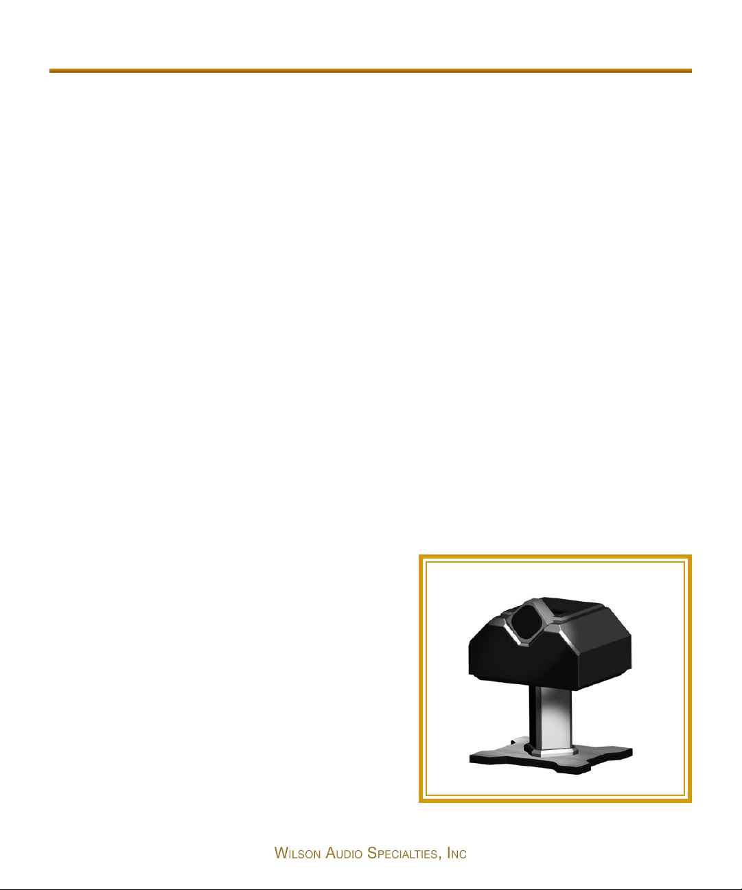
WATCH Center
Specifically designed to excel at center
channel functions, WATCH Center is extremely
dynamic with high sensitivity and robost power
handling. Unlike most center channels, it provides listeners not only with optimal on-axis
response, but also smooth, linear, off-axis performance. This is, in part, a result of Wilson
PDC™ (Phase Delay Correction) technology first
developed for the WAMM® and X-1 Grand
Figure 1
11
Page 12
SLAMM systems and later applied to the rest of the Wilson Line. PDC allows for optimal tuning of a loudspeaker for various listening distances and heights and gives listeners much greater control over their sound.
The WATCH Center was designed from the ground up as a center channel. It is
not merely a standard speaker that was tipped onto its side. The center channel was
voiced and optimized to truly represent dialogue for movies as well as music and
vocals when used in a multi-channel audio setup.
Of course, WATCH Center lives up to Wilson’s high standards of cutting edge
design, superior build quality, and stunning sonic performance. WATCH Center is
shielded and is available with a matching
stand.
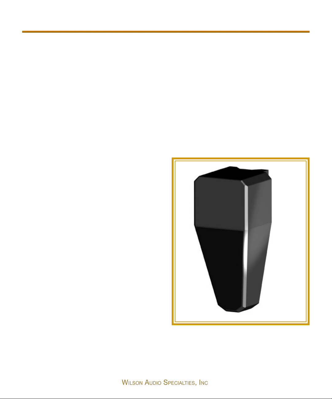
WATCH Surround
WATCH Surround is a perfect example of performance disproportionate to
size. With strong power handling capacity
and low end frequency response reaching
45Hz, this speaker will take your surround
sound to new heights. Unlike most surround speakers, WATCH Surround is more
than a noisemaker. It brings accuracy,
dynamics, and emotion to your theater, and
with its gorgeous Mirrorgloss™ finish, it
looks right at home on your wall.
The greatest challenge for any wallmount loudspeaker is accounting for the
deleterious interaction with the wall and
Figure 2
ceiling, as well as degradation caused by
the mount itself. This causes frequency nonlinearities -accentuating some frequencies
and effectively masking others. WATCH Surround minimizes wall/ceiling resonant
interactions through its advanced mounting system. Using state of the art materials
12
Page 13

Watch Dog Introduction - continued
technology first developed for the X-1 Grand SLAMM, WATCH Surround provides
stunning results.
The Surround is mounted to its bracket by strategically located spikes, further
reducing wall interaction and resonance. The Surround can also be rotated towards
the listening position, offering improved integration with the front speakers and better
imaging.
CONCLUSION
Finally, a subwoofer designed and manufactured with the same commitment to
excellence that has characterized all products from Wilson Audio. The WATCH Dog
combines Olympian structural, design, and finish considerations with superior sonic
quality. It is this approach that distinguishes Wilson Audio products. As a part of a
truly high-end multi-channel system, or in a music system, the WATCH products offer
unparalleled performance, quality of build, and longevity. Wilson Audio delivers a product that maintains the strictest structural tolerances, durability, and reliability. You will
have consistent, repeatable performance, unaffected by the climatic conditions, anywhere in the world. The WATCH Dog, as well as the other WATCH products, will provide an experience with film or music only obtainable through Wilson products.
13
Page 14

Page 15
Page 16

16
Page 17

In Your Room
Note: The following section presents conceptual and practical information
on room acoustics. These concepts for two-channel audio become even more
important when dealing with multi-channel audio or home theater. The presence
of two or more speakers in a room only increases the amount of setup difficulties and speaker interactions. Careful study of the room acoustics principles
herein, followed by evaluating your own room configuration, will result in a
marked improvement in the performance of your multi-channel system.
Section 2.0 - Room Reflections
There are three commonly encountered room reflection problems: slap-echo,
standing waves, and comb filter effects.
Slap Echo
Probably the most obnoxious form of reflection is called “slap echo.” In slap
echo, primarily mid-range and high frequency sounds reflect off of two parallel hard
surfaces. The sound literally reverberates back and forth until it is finally dissipated
over time. You can test for slap echo in any room by clapping your hands sharply in
the middle of the room and listening for the characteristic sound of the echo in the
mid-range. Slap echo destroys the sound quality of a stereo system primarily in two
ways:
• Adding harshness to the upper mid-range and treble through
energy time storage.
• Destroying the delicate phase relationships which help to establish
sound stage and image localization cue.
Nonparallel walls do not support slap echo, but rather allow the sound to dif-
fuse.
Slap echo is a common acoustical problem in typical domestic listening rooms
because most of these rooms have walls of a hard, reflective nature, occasionally
17
Page 18

interrupted by curtains or drapes. Slap echo can be controlled entirely by the application of absorptive materials to hard surfaces, such as:
• Sonex
• Airduct board
• Cork panels
• Large ceiling to floor drapes
• Carpeting to wall surfaces
In many domestic listening environments, heavy stuffed furnishings are the primary structural control to slap echo. Unfortunately, their effectiveness is not predictable. Diffusers are sometimes also used to very good subjective effect, particularly
in quite large rooms. Sound absorbent materials such as described above will alter the
tonal characteristic of the room by making it sound “duller,” much heavier in the bass,
less “bright and alive,” and “quieter.” These changes usually make the room more
pleasant for conversation, but sometimes render it too dull in the high frequencies to
be musically involving. Diffusers, on the other hand, tend not to change the high frequency tonal balance characteristic of the room, but make the sound more “open.” A
combination of absorptive and diffusive treatments is usually the best approach.
Standing Waves
Another type of reflection phenomenon is standing waves. Standing waves
cause the unnatural boosting of certain frequencies, typically in the bass, at certain
discreet locations in the room. A room generating severe standing waves will tend to
make a loudspeaker sound one way when placed in one location and entirely different
when placed in another. The effects of standing waves on a loudspeaker’s performance are primarily, as follows:
• Tonal balance - bass too heavy
• Low-level detail - masked by long reverberation time - low frequency standing waves
18
Page 19

In Your Room - Continued
• Sound staging - low frequency component of image shifted
Standing waves are more difficult to correct than slap echo because they tend
to occur at lower frequencies, whose wave lengths are long enough to be ineffectively
controlled by absorbent materials such as Sonex. Moving speakers about slightly in
the room is, for most people, their only control over standing waves. Sometimes a
change of placement as little as one inch can dramatically alter the tonal balance of a
system affected by standing wave problems. Fortunately, minor low frequency standing waves are sometimes well controlled by positioning tube traps in the corners of
the room. Very serious low frequency accentuation usually requires a customdesigned bass trap system.
Low frequency standing waves can be particularly troublesome in rooms constructed of concrete or brick. These materials trap the bass in the room, unless it is
allowed to leak out of the room through large window and door areas.
In general, placement of the speaker in a corner will excite the maximal number
of standing waves in a room and is to be avoided for most direct radiator, full range
loudspeaker systems. Some benefit is achieved by placing the stereo pair of loudspeakers slightly asymmetrically in the listening room so that the standing waves
caused by the distance between one speaker and its adjacent walls and floors are not
the same as the standing wave frequencies excited by the dimensions in the other
channel.
Comb Filter Effect
A special type of standing wave, noticeable primarily in the midrange and lower
high frequencies, is the so-called “comb filter effect.”
Acoustical comb filtering occurs when sound from a single source, such as a
loudspeaker, is directed toward a microphone or listener at a distance. The first sound
to reach the microphone will be the direct sound, followed by delayed reflected sound.
At certain frequencies cancellation occurs because the reflected sound lags in phase
relative to the direct sound. This cancellation is most apparent where the two are 180
degrees out of phase. There is augmentation at other frequencies where the direct and
19
Page 20

the reflected sounds arrive in phase. Because it is a function of wave length, the comb
filter effect will notch out portions of the audio spectrum at regular octave-spaced
intervals.
The subjective effect of comb filter effects (such as is shown in Figure 3) is as
follows:
• Added roughness to the sound
• Reduction of harmonic richness
• Smearing of lateral sound stage image focus and placement
Comb filter effects are usually caused by side wall reflections. They are best
controlled by very careful speaker placement and by the placement of Sonex or air
20
Figure 3
Page 21

In Your Room - Continued
duct panels applied to that part of the wall where the reflection occurs.
Section 3.0 - Resonance
Resonance in listening rooms is generally caused by two sources:
• The structures within the listening room
• The volume of the air itself in the listening room
Structural Resonance
Structural resonances are familiar to most people as buzzes and rattles, but this
type of resonance usually only occurs at extremely high volume levels and is usually
masked by the music. In many wood frame rooms, the most common type of structural resonance problem is “booming” of walls and floors. You can test for these very
easily by tapping the wall with the heel of your hand or stomping on the floor If it is a
wooden floor, this is done to detect the primary spectral center of the resonance. To
give you an idea of what the perfect wall would sound like, imagine rapping your hand
against the side of a mountain. Structural wall resonances generally occur in the low
to mid-bass frequencies and add tonal balance fullness to any system played in that
room. They, too, are more prominent at louder levels, but their contribution to the
sound of the speaker is more progressive. Rattling windows, picture frames, lamp
shades, etc., can generally be silenced with small pieces of caulk or with blocks of
felt. Short of actually adding additional layers of sheet rock or bookshelves to flimsy
walls, there is little that can be done to eliminate wall resonances.
Air Volume Resonance
The volume of air in a room will also resonate at a frequency determined by the
boundary location and size of the room. Larger rooms will r
cy than will smaller rooms. Air volume resonances, wall panel resonances, and low frequency standing waves combine to form a low frequency coloration in the sound. At
esonate at a lower frequen-
21
Page 22

its worst, the result is a grossly exaggerated fullness which tends to obscure detail
and distort the natural tonal balance of the speaker system. Occasionally, however, a
small-amplitude resonance can add a desirable warmth to the sound - an addition
some listeners prefer. Tube traps, manufactured by the ASC corporation, have been
found to be effective in reducing some low frequency room colorations. Custom
designed and constructed bass traps, such as perforated Helmholtz resonators, provide the greatest degree of low frequency control.
22
Page 23

232627
Page 24

Page 25
Page 26

Page 27

Initial Setup
Section 4.0 - Initial Setup
We strongly recommend that a trained and certified Wilson Audio dealer assist
you in your home with the set up and placement of your WATCH Dog subwoofer. They
are well versed in Wilson Audio Setup Procedure (WASP) and the methods best used
with our products to provide you with the most satisfying results. In this section you
will find the necessary tools and information in the event dealer assistance is not available.
If you have not read the previous section on room acoustics, we recommend
that you do so now. It will provide you with valuable information for determining the
overall best speaker placements and listening position. This section contains information on how to fully evaluate the acoustical qualities of your existing room in the proper placement of your WATCH Dog as well as the placement of other speakers in your
listening environment.
System Setup
We recommend that you setup your multi-channel system as follows:
• Perform an acoustical analysis of your existing room.
• Find and mark the zones of neutrality for each of the speakers in
• Follow the setup procedures outlined in Section 5 and your left
• Perform the final system setup and fine tuning steps outlined in
Zone of Neutrality
The zone of neutrality is a location in your room where the speakers will sound
the WATCH system (more specific details are found below).
and right channel owner’s manual.
Sections 5 and 6.
Page 28

most natural. This location is where the speakers interact the least with the room. (We
realize that the location of your WATCH speakers might not be very flexible.) We recommend that you wait to spike your speakers until the final system setup is completed in Section 6.
To find the zone of neutrality do as follows:
1. Stand against the wall BEHIND the location where you intend to position
your loudspeakers. Speaking in a moderately loud voice and at a constant
volume, project your voice out into the room. Your voice will have an overly
heavy, “chesty” quality because of your proximity to the rear wall.
2. While speaking, slowly move out into the room, progressing in a direction
parallel to the side wall. It is helpful to have another listener seated in the lis-
tening position to assist you during this process. Listen to how your voice
“frees up” from the added bass energy imparted by the rear wall boundary.
Also notice that your voice is quite spatially diffuse (to your assistant, your
28
voice will sound spatially large and difficult to localize) as you begin to ease
away from the rear wall.
3. At some point during your progression forward into the room, you will
observe a sonic transition in your voice; it will sound more tonally correct
and less spatially diffuse (your assistant can now precisely localize the exact
origin of your voice). When you hear this transition, you have enter
inner edge of the “Zone of Neutrality.” Place a piece of tape on the floor to
mark this location. Although it will vary from room to room, the zone in most
rooms begins between two and a half or three feet from the rear wall.
4. Continue to walk slowly away from the rear wall. After some distance, usual-
ed the
Page 29

Initial Setup - Continued
ly one to two feet past the first piece of tape, you will begin to hear your
voice lose focus and appear to reflect (echo) in front of you. This is caused
by the return of the room’s boundary contribution; your voice is now inter-
acting with the opposite wall. At the point where you begin to hear the
reflected sound of your voice, you have reached the inner edge of the “Zone
of Neutrality.” Place a piece of tape on the floor and mark this location. The
distance between the “inner” and “outer” edge tape marks is usually
between eight inches (for small, interactive rooms) and three feet (for large,
more neutral rooms).
5. Now position yourself against the side wall perpendicular to the intended
speaker location. Stand between the two tape marks. Using the same pro-
cedure as above, begin moving into the room toward the opposite side wall,
progressing between the two pieces of tape. As above, listen for the point in
the room where your voice transitions from bass-heavy and diffuse to neu-
tral. Mark this point with tape. Continue your progression until there is an
obvious interaction with the opposite wall in front of you and mark this point
with tape. The four pieces of tape now form a rectangle that establishes the
Zone of Neutrality for the loudspeaker located on that side of the room.
Using the four marks as your guide, tape an outline to define the bound-
aries of the rectangle.
6. Repeat this process for each speaker location individually. These are your
Zones of Neutrality, one for each channel.
Note: The more reflective or “live” sounding the room is, the more difficult
it will be to detect the changes in your voice; thus, you may have to repeat this
process until the zones have been determined.
29
Page 30

Section 4.1 - Choosing a Listening Position
Home Theater
Decide where you want your listening position to be. Please remember that
your WATCH System can fill most rooms with beautiful sound. However, we want to
ensure that you enjoy the benefits of the group delay adjustment features that are built
into all Wilson Audio products.
Speaker Placement vs. Listening Position - Main Speakers
The location of your listening position is as important as the careful setup
placement of your speakers in your room. The listening position should ideally be no
more than 1.1 to 1.25 times the distance between the left and right channel tweeters
on each speaker. Therefore, in a long rectangular room of 12’ x 18’, if the speaker
tweeters are going to be 9’ apart, you should be sitting 9’11’’ to 11’3’’ from the speaker. This would be about halfway down the long axis of the room. Experiment carefully
for best low frequency response.
Some people place the speakers on one end and sit at the other end of the
room. Needless to say, this will not yield the finest sound. Carefully consider your listening position for optimal performance. Our experience has shown that any listening
position which places your head closer than 14” to a room boundary will diminish the
sonic results of your listening.
Another important aspect of speaker placement is how far the speakers are
positioned from the wall behind them. The closer the loudspeaker is to the back wall,
the more pronounced the low bass energy and centering of the image will be.
However, this comes at a definite reduction in stage size and bloom, as well as a deterioration of upper bass quality. The best locations are those that maximize the proper
balance of these two factors. Remember, if you are partial to bass response or air and
bloom, be careful not to overcompensate your adjustments to maximize their effects.
Improperly balanced systems (setups that favor one factor at the expense of others)
are sometimes pleasing in the short term, but long term satisfaction is always
30
Page 31

Choosing a Listening Position
achieved through proper balance.
Center Channel
After determining the general area for the Left and Right Channels, determine
the best place for your Center channel. The following center channel configurations
are possible:
• On the floor with the speaker angled up towards the listener.
• Mounted on a stand with no upward rotation.
• Mounted on a stand with longer spikes in the front of the stand
and shorter spikes in the back, allowing the stand and speaker to
be rotated up toward the listener.
• Mounted above the TV on a custom made bracket.
• Mounted upside down on the ceiling, angled down towards the
listener.
With the exception of Center channels mounted on the ceiling, each of these
options allow for some fine tuning of the Center channel placement. If you are mounting the Center channel on the ceiling, be sure to choose the location carefully as you
will not be able to easily adjust it once it is mounted. A poor placement of the Center
channel will hamper its integration with the rest of the system. As a general rule, the
distance from the main Left and Right channels, as well as the Center channel (as
measured from the tweeters) should be equal in their relationship to the listening position. This maintains the time coherence of the three front loudspeakers. Ultimately, the
Center channel phase delay correction will be made via the sliding tweeter module.
Wilson recommends that the Center channel be positioned as centrally between
the Left and Right speakers as possible. Using the Wilson Audio Setup Procedure,
experiment with the fore to aft placement of the center channel. This process will help
you find the location that offers the smoothest left, right and center channel integration. More information on this process is included in Section 4.0.
31
Page 32

Speaker Orientation
Speaker placement and orientation are two of the most important considerations in obtaining superior sound. The first thing you need to do is minimize the influence of the side walls on the sound of your system. Speakers placed too close to the
side walls will suffer from a strong primary reflection. This can cause out-of-phase
cancellations, or comb filtering, which will cancel some frequencies and change the
tonal balance of the music. A good place to start is with the speakers about 18” from
each wall and, if you need to move them relative to the side wall, move them away
from the wall, not closer.
Surround Channel
Wilson Audio has done everything possible to eliminate the boundary interactions caused by mounting a speaker onto the wall. The mounting bracket allows for
significant improvements in detail, speed, and clarity. The surround channels will perform well in almost any location in which they are placed. The mounting bracket and
the careful design of the surround channel has eliminated most of the sonic problems
encountered when placing a standard speaker too close to a boundary. Nevertheless,
we have performed extensive testing on the surround channel and found that significant improvement on speaker linearity and integration can be achieved by careful
selection of the surround channel mounting location.
We realize that the location of the surround channel is generally set by the
architecture of the room. However, if you have some flexibility in locating your surrounds, we suggest that you use WASP to to find the zone of neutrality. Be sure to listen for room modes and frequency response peaks or dips.
WATCH Dog Subwoofer
Because the WATCH Dog’s frequency range is limited to the sub-frequency
bass range, its placement requirements are slightly different than for a full frequency
speaker. The WATCH Dog is shipped with casters installed on the bottom of the cabinet. Leave the casters on the Dog as you move it to its desried location.
32
Page 33

Choosing a Listening Position - continued
The ideal position of the WATCH Dog subwoofer is somewhat dependent on its
primary use. In home theaters where the WATCH Dog is used as the Low Frequency
Effects (LFE) Channel, it may be located in a variety of positons, depending on architectural considerations. In general, the lower frequency range will be reinforced by
room boundaries and corners. Since most of the information contained in the LFE
channel is in the sub-frequency bass range, with little information in the mid and upper
bass, there are some advantages to placing the WATCH Dog near the room boundaries or near a corner. Some care is needed to avoid introducing upper-bass colorations caused by corner placement. While surround processors provide the low frequency equalized signal for the LFE Channel, it has been our experience that in some
systems it is desirable to use the Low Pass crossover on the WATCH Dog Control
Panel to additionally limit upper bass range. This is particularly important and useful
when the WATCH Dog is placed in the corner. Since all Wilson Audio Speakers are
phase and time coherent, it is very important to time align the WATCH Dog in the
room using the Phase Control on the Control Panel. This procedure will be described
in Section 6.0.
Section 4.2 - Watch Dog Setup in a Music System
The WATCH Dog subwoofer was designed in conjunction with all Wilson Audio
loudpseakers. All Wilson Audio loudspeakers are designed to be audibly phase and
time coherent. The WATCH Dog subwoofer was engineered to extend and enhance
the low frequency performance of music systems without compromising the phase
and time accuracy of Wilson loudspeakers. The powerfully versatile Phase control on
the Control Panel allows the WATCH Dog to be optimized in the time domain within
the listening environment. Correct Phase setup of the WATCH Dog allows proper integration in the time domain between the WATCH Dog and the main loudspeakers,
resulting in greater frequency linearity, dynamic impact, sound-stage accuracy, and
speed. See Section 6 for detailed instruction on the setup of the Control Panel.
In music systems, to achieve the most coherent spacial and tonal presentation,
33
Page 34

it is best to position the WATCH Dog behind the plane of the main speakers.
Placement in front of the main loudspeakers, or behind the listener, can potentially
compromise the phase accuracy in two-channel music systems. This will result in a
less coherent presentation of the spatial, dynamic, and tonal information. Successful
integration with the main loudspeakers is more easily achieved when the WATCH Dog
is placed between and behind the two main speakers or in the left or right corners
behind the main loudspeakers. Corner placement provides the greatest low frequency
reinforcement, but care is required to avoid upper bass colorations resulting in less
coherent integration with the main speaker. Corner induced upper-bass colorations
can be reduced by lowering the Low Pass Filter frequency crossover point. Further
correction of room-induced anomalies in the in-room bass response can be minimized
with the WATCH Dog’s unique Bass Equalization Control. See Section 6 for detailed
information on critical setup of the WATCH Dog Control Panel.
The WATCH Dog can be used simultaneously as both the LFE channel subwoofer in the surround mode and as the subwoofer to the main speakers when listening to music. This is achieved by switching between the “Line” and “Processor” inputs
on the Control Panel. Low and High Pass filter settings are also switchable, allowing
the WATCH Dog to be optimized for both music and home theater - even within the
same system. See Section 6 for detailed information on the switching facility of the
WATCH Dog Control Panel.
Section 4.3 - Initial Setup Summary
When used in a home theater system as the LFE channel, the WATCH Dog can
be positioned in a variety of areas within the room successfully. Room boundaries and
corners enhance low frequency coupling with the room, but care is required in attending to resulting upper bass colorations.
When used in a music system, the subwoofer integrates more consistently with
the main speakers when placed behind the plane of the speakers or in a corner of the
room behind the main speakers. Careful setup using the Phase control and the Low
and High Pass filters is necessary to optimize low bass performance and to ensure
34
Page 35

Choosing a Listening Position - continued
proper integration with the main loudspeakers.
35
Page 36

Page 37

Page 38

38
Page 39

WATCH Dog Setup
Section 5.0 - WATCH Dog Setup
Preparation
You will need the following items:
• Supplied hardware kit
• Tape measure
• Known listening position
• Electric screwdriver
• Phillips head drive bit
Uncrating the WATCH Dog
A minimum of two strong adults are required to set up the WATCH Dog. The
WATCH Dog is very heavy and care should be taken to prevent injury.
1. With the crate lid facing up, unscrew the wood screws securing the lid.
Remove the lid. Remove the foam packing material that is positioned
between the casters (on the bottom of the WATCH Dog). The WATCH Dog
will not roll out of the crate with this packing material in place.
2. Rotate the crate so that the WATCH Dog is upright.
3. While one person holds the crate, another person should gently roll the
WATCH Dog out of the crate. Be careful not to scratch the sides of the
painted enclosure.
4. Move the WATCH Dog into the desired location. It is recommended that you
leave the casters attached to the bottom of the WATCH Dog during the
positioning process.
39
Page 40

Note: Be careful not to touch the driver element when you are moving your
WATCH Dog!
Section 5.1 - Connecting the WATCH Dog - Home Theater
The WATCH Dog can be connected in a variety of ways depending on your system needs. It can be used as the LFE (Low Frequency Effects) channel for a dedicated
home theater system, or it can be used to extend the bass in a two-channel music
system. In systems where it is desirable to use the WATCH Dog with both surround
modes and two-channel music mode, you can switch between the two via the WATCH
Dog’s control panel.
The WATCH Dog is also capable of accepting either balanced (XLR) or single
ended (RCA) cable connection from your preamplifier or surround processor. Your
choice will depend on the configuration of your particular preamp or surround processor.
Connection With a Surround Processor
Make sure the WATCH Dog power is “off” and the Level Control on the WATCH
Dog control panel is in the “MIN” position during the connecting process. Locate the
input section of the WATCH Dog on the rear of the subwoofer (See Figure 4). The
Processor Input of the WATCH Dog is designated for use with the LFE (Low
40
Figure 4
Page 41

WATCH Dog Setup - Continued
Frequency Effects) outputs of a surround processor. Balanced (XLR) or Single Ended
(RCA) connecting cables may be used, depending on the connector type used on your
surround processor. Connect the LFE output of the processor to the “Processor Input”
of the WATCH Dog.
On the WATCH Dog control panel, locate the switch labeled “BAL/SINGLE.”
Select “BAL” for use with balanced cables or “SINGLE” for use with single ended
cables (See Figure 5). In the same section of the control panel, locate the switch
labeled “PROCESSOR,”
“REM,”and “LINE.” Select the
“PROCESSOR” input (See Figure
5). On the control panel, locate
the switch label “HP IN” and “HP
OUT.” Select “HP OUT” (See
Figure 6). On the control panel,
locate the switch labeled “LP IN”
and “LP OUT.” Select “LP OUT”
(See Figure 7).
Proceed to Section 6,
“Control Panel Setup and Final
Tuning,” to continue the setup of
your subwoofer.
Wilson Audio has engineered, in conjunction with Marsh Design, very flexible
and high quality high and low pass crossover filters for the WATCH Dog. Setup and
configuration of these filters is discussed in Section 6 entitled “Control Panel Setup and Final Tuning of the WATCH
Dog.”
Figure 5
Section 5.2 - Connecting the Dog -Two-Channel System
Bypassing The High Pass Filter
In systems where the main speakers are full range, the WATCH Dog can be
41
Page 42

configured more successfully without the use of the High Pass Filter. There is a normal
bass roll-off that occurs naturally in your listening room. This effect acts like a six dB
per octave low pass filter and rolls off the bass from your main speakers. By carefully
using the WATCH Dog’s Low Pass filter controls, along with the Bass Equalization and
Phase controls (discussed in Section 6), you can successfully integrate the main loudspeakers in your system with the WATCH Dog without the use of the High Pass Filter.
Make sure the WATCH Dog power is off during the connecting process. Locate
the input section of the WATCH Dog on the rear of the subwoofer (See Figure 4). The
left and right “Line Level” inputs are used when the WATCH Dog is the subwoofer to
two main loudspeakers. The WATCH Dog automatically sums the information from the
left and right channels for the subwoofer. The WATCH Dog inputs are configured for
both balanced (XLR) and single ended (RCA) cables.
When connecting the WATCH Dog without the use of the High Pass Filter, a
second output from your preamplifier is required. If your preamplifier does not have
two sets of outputs, consult with your dealer about using high quality “Y” connectors
to facilitate connecting your subwoofer. From one of the preamp outputs, connect
your preamp directly to your main amplifier. From a second set of preamp outputs,
connect both left and right channels to the Line Level Input of the WATCH Dog.
On the WATCH Dog control panel, locate the switch labeled “BAL,” and “SINGLE.” Select “BAL” for use with balanced cables, or “SINGLE” for use with single
ended cables (See Figure 5). In the same section of the control panel, locate the
switch labeled “PROCESSOR,” “REM,” and “LINE.” Select the “LINE” input. On the
control panel, locate the switch label “HP IN,” “REM,” and “HP OUT” (see Figure 6).
Select “HP OUT.” On the control panel, locate the switch labeled “LP IN,” “REM,” and
“LP OUT” (See Figure 7). Select “LP IN.”
Proceed to Section 6, “Control Panel Setup and Final Tuning,” to continue the
setup of your subwoofer.
Utilizing The High Pass Filter
The WATCH Dog employs a high quality High Pass Filter as a part of its
crossover design. The High Pass Filter can be used to filter bass from the main loud-
42
Page 43

WATCH Dog Setup - Continued
speakers. This can be desirable in systems where the main loudspeakers have limited
bass dynamics or if the main power amplifier is low power.
Make sure the WATCH Dog power is off during the connecting process. On the
rear of the subwoofer, locate the Line Level inputs of the WATCH Dog. Connect the
preamplifier output, left and right, to the Line Level input of the WATCH Dog (See
Figure 4). Use the XLR inputs for balanced cables or the RCA inputs for single-ended
cables.
Locate the Line HP Output (See Figure 4) on the rear of the amplifier. These
connectors pass the high pass section of the signal to your main amplifier for your
loudspeakers. Connect the Line HP Output, left and right, of the WATCH Dog to the
inputs of your power amplifier. Use the XLR inputs for balanced cables or the RCA
inputs for single ended cables. On the WATCH Dog control panel, locate the switch
labeled “BAL,” and “SINGLE.” Select “BAL” for use with balanced cables, or “SINGLE” for use with single-ended cables (See Figure 5). In the same section of the control panel, locate the switch
labeled “PROCESSOR,”
“REM,” and “LINE.” Select the
“LINE” input.
Locate the switch on the
control panel labeled “HP IN”
and “HP OUT” (See Figure 6).
This switch defeats and
engages the high pass filter.
Turn the switch to the HP IN
position.
Locate the switch on the
control panel labeled “HP 6
dB” and “HP 12 dB” (See
Figure 6). This switch changes
the slope of the high pass filter
to either 6 decibels per octave
Figure 6
43
Page 44

or 12 decibels per octave. The
position of this switch will be set
in its final position in the final
tuning stages of the WATCH
Dog. For now, set the switch to
the 6 dB per octave position.
Proceed to Section 6,
“Control Panel Setup and Final
Tuning,” to continue the setup of
your subwoofer.
Figure 7
44
Page 45

WATCH Dog Setup - Continued
45
Page 46

Page 47

Page 48

48
Page 49

Control Panel Setup and Final Tuning
Note: Before proceeding with the Control Panel setup and configuration,
please connect your system as outlined in Section 5, which contains valuable
information needed before proceeding further.
Section 6.0 - Control Panel Setup and Final Tuning
Preparation
In order to realize the full potential of your WATCH Dog, we recommend that
you have a trained Wilson Audio Specialist install and perform the final adjustment and
setup of your subwoofer. Your dealer will have personnel trained in the art of WATCH
Dog setup. If you choose to do the installation yourself, here are some guidelines to
assist you. These guidelines come from many years of experience and should be followed closely to ensure the best possible result from your WATCH Dog.
You will need the following items:
• Supplied WATCH Dog Setup CD
• Supplied 5/32 T-handled Allen Wrench
• Radio Shack dB Meter
• Pen and paper to make notes
Using the Allen wrench, remove the top clear acrylic cover plate that protects
the control panel. Double check the switch and control settings to ensure that they are
in the proper positions as outlined in Section 5. In this section, you will be adjusting
and fine tuning the WATCH Dog control panel.
Locate the main power switch on the rear of the WATCH Dog, below the amplifier heatsinks. Toggle the switch to the “on” position. This powers the WATCH Dog
into the “standby” mode and can be left on. Locate the power switch on the front of
the WATCH Dog, behind the grille. Depress the switch and check to see that the front
panel LED is illuminated.
49
Page 50

Note: We recommend that you turn the main power switch on the rear of
amplifier to the off position and disconnect the power cord during lightning
storms or when you are away.
Section 6.1 - Notes From David A. Wilson on Using the Test CD
Wilson Audio has provided a test CD to aid you in the setup of your WATCH
Dog subwoofer. The following comments and recommendations refer most precisely
to the use of the W
these procedures can also be used to optimize the WATCH Dog to the left and the
right channels of a multi-channel home theater system.
Subwoofer Placement
The WATCH Dog possesses sophisticated low pass filter control features, as
well as the ability to continuously vary phase angle. As a result, placement of the
WATCH Dog is not as critical as with most other designs. The WATCH Dog can be
successfully placed between and slightly behind the left and right speakers. However,
because of its flexible control, the WATCH Dog is equally successfully placed in a variety of locations in the listening room - such as on a side wall or behind the listener.
ATCH Dog subwoofer in a two-channel music system. However,
Filtering of LF to the Left & Right Speakers
With two-channel music systems in moderate sized rooms, where high volumes
are not required, the left and right speakers are often run full range. This is particularly
true when Wilson Audio speakers are used, as a reult of their low distortio and robust
power-handling capabilities. The usual rationale for this approach is that the “fullrange” signal will lose some of its midrange and high frequency transparency going
through the active high pass crossover. While this is theoretically true, what is more
important is the more complex low frequency room interaction that will occur between
the subwoofer’s output and the full range output of the L and R channels. This LF
interaction is greatly reduced if LF to the L & R speakers is filtered out. For the greatest finesse in music reproduction you should experiment with both approaches.
50
Page 51

Control Panel Setup - Continued
Initial placement of the L & R speakers
If both the WATCH Dog and the main speakers are new to the system, we recommend that the main speaker positions be carefully optimized for overall sound quality before introducing the subwoofer. To prevent equipment damage and facilitate
movement, keep the WATCH Dog out of the listening area during the two-channel
setup phase.
The WATCH Dog CD contains a variety of test tones to aid you with the set up
of your subwoofer.
1. If your playback electronics have signal level metering facilities, use track 1
(1 kHz tone) to assure equal signal levels to both left and right loudspeakers.
If it is physically and electrically in the system at this point, the subwoofer’s
output level control should be turned all the way down.
2. Assure that the left and right loudspeakers are in phase by using track 4,
(BLN - bandwidth limited noise ). The noise should appear to come from
exactly between your left and right loudspeakers.
Figure 8
51
Page 52

3. If you have either a spectrum analyzer or a sound pressure level (SPL) meter,
you should measure and document the in-room response of your L & R
loudspeakers, running full-range, without subwoofer contribution. This will
give you a baseline measurement. While you can measure each channel
individually, it is more expedient to measure both simultaneously using the
(Mono) test signals. Measurement locations for the microphone should
include one at ear height at the main listening location. Additional locations
could include two meters, both left and right, of the primary listening posi-
tion, as well as halfway between the primary position and the back wall.
These readings must be averaged together. Expect measurements taken
close to walls to show substantially more LF energy than those taken near
the center of the room. Use the dB-C weighting, or better yet, if available,
the “Flat”/ non-weighted scale of your instrument. See Figure 8 which com-
pares dB-A & dB-C weighting. The more commonly used dB-A scale, on the
other hand, is intended to correspond to the ear’s “frequency response” at
low SPL and should never be used to calibrate low frequency levels. Please
note that, even at 50 Hz, the dB-C scale is still down approximately 2 dB
relative to 800 Hz. Don’t be disappointed, therefore, if your dB-C scale
measurements show a gradual roll off in the bass. If your measurements do
follow the profiled roll off, it indicates a very linear speaker/room response.
Use track 2, (pink noise), for spectrum analysis measurements. For meas-
urements using a SPL meter, use tracks 6 through 16, (1/3 octave BLN
beginning at 200 Hz and going down to 20 Hz). Document your measured
results.
Warning: Tracks 17 through 27 are sine wave tones at the 1/3-octave center frequencies. These should not be used to perform in-room frequency
response estimates due to gross inaccuracies which will be created by standing
waves. Pure tones are included to scan for mechanical resonances and other
distortions.
52
Page 53

Control Panel Setup - Continued
Notes Regarding the Interpretation of Measurements:
A. Use “slow” meter response ballistics to help average out the
reading… and to keep from going crazy trying to read it!
B. Ears and meters are not directly interchangeable. They neither
sample nor process the sound in a completely analogous
manner.
4. If you choose to use the high pass section of the WATCH Dog controller to
roll off bass to your main speakers, you can use your measured data to
select a low pass (LP) frequency. The suggested setting for the high pass
frequency is at the point where the measured frequency curve begins to
“roll-off,” specifically at the frequency that is minus three to minus six dB
(relative to the average level of the full-range response). If specific measure-
ments are not available, I like to start, as a general rule, at 50 Hz with an 18-
dB/octave LP slope. I believe that the vast majority of loudspeakers with
which the WATCH Dog will likely be partnered should have enough clean
output and power handling in the 40-50 Hz region to allow this approach.
However, some rooms exhibit so much loss in the LF that the L & R speak-
ers may have difficultly in that region and need help from the subwoofer up
to 60-80 Hz. Another scenario might include problematic room acoustics,
with a significant upper bass peak. In such a case, correction may be
achieved by running the WATCH Dog up to 120-140 Hz and using its EQ to
notch out the room peak. This is one area where acoustical measurements,
as described above, are of great benefit.
Introduction of The WATCH Dog Into Your System
5. Check to see that the L & R loudspeaker power amps are “Off” or on
53
Page 54

“Standby.”
6. Ensure that all system cabling is correct and secure. At this point in the set
up process, the input switches should be configred properly, according to
instructions elsewhere in this manual. It is now time to optimize Level, Phase
and EQ settings.
7. If you are filtering the bass to your L & R speakers, select “HP In,” and set
the high pass frequency according to the acoustical measurements you
have taken. Start with HP 12 dB per octave slope.
8. Initially select the low pass frequency 10 % lower than the setting for the
high pass frequency.
9. Select “LP In” and LP 18-dB / octave slope.
10.Initially set the Phase control at 90°.
54
11.Select “EQ Out” at this point in the calibration.
12.The output level control should be in the “Min” position.
13.Turn on the program source components and pre-amplification.
14. After two minutes of stabilization time, turn on your WATCH Dog subwoofer.
15. After two additional minutes of stabilization time, turn on your L & R chan-
nel power amplifiers.
Page 55

Control Panel Setup - Continued
16. Using track 2 (pink noise), turn the L & R speakers up to 75 dBC; note the
level setting.
17. While the L & R speakers are playing the pink noise, slowly advance the
output level control on the WATCH Dog until the low frequencies seem to be
in balance with the rest of the spectrum. If you have a spectrum analyzer,
adjust the output level for greatest linearity and extension.
18. Note the output level setting.
19. Next, slowly rotate the Phase control from 90° counter clockwise to 0° and
notice how LF levels will change; note the position between 0° & 90° where
the LF output is greatest.
20.Repeat this process from 90° to 180°, again noting the position where LF
Figure 9
55
Page 56

output is greatest. These two settings become your “semifinalists.”
21.Go to track 28 (drum and guitar music) and compare the sound of your two
Phase “semifinalists.” Listen for cleaner LF attack and greater weight to
select your “winner.” Note the winning setting.
22.Use two tracks, 29 and 32, to establish the WATCH Dog’s upper frequency
limit with the LP frequency control setting. What you are looking for is a set-
ting that is low enough to keep from adding artificial chestiness to the male
voice in track 32, yet high enough to provide convincing, linear low frequen-
cy continuity in track 29. Note the setting.
23.Using the same tracks (29 & 32) and similar listening-judgment criteria, opti-
mize the setting of HP frequency control, which establishes the low frequen-
cy limit of your L & R speakers. Note the setting.
24. At this point in the process, it is instructive to measure the acoustic
response of the combined L & R system a second time, but this time with
the addition of the subwoofer. Compare the results of this measurement with
your prior measurements made without the subwoofer. Document these new
measurements. You should now clearly observe more output below 40 Hz as
well as good linearity.
25.Now is a good time to experiment with different filter slopes. Simply follow
the same procedures as above, being careful to note all settings. This sec-
ond experiment can then be compared with the first, using music and meas-
urements. Pick the approach that gives the most satisfying musical results.
To EQ Or Not To EQ
56
Page 57

Control Panel Setup - Continued
Using equalization (EQ) in order to optimize the performance of a loudspeaker
is somewhat like a medicine that, while useful, has serious potential side effects.
Carefully and minimally used, it can moderate some serious acoustical problems, with
little or no down side. However, applied injudiciously, it will cause more problems than
it will cure.
The EQ circuitry in the WATCH Dog operates only in the Low Pass (LP) function; i.e. it only EQ’s the WATCH Dog. Therefore, it will have no direct effect on the L &
R (or other channel) loudspeakers.
Indications for the use of the WATCH Dog EQ would include the following:
A. A large LF peak caused by compounded room modes or interac-
tion with a nearby boundary. Corner placement of the WATCH Dog
is more likely to excite modes than a placement at least 1 meter
from a corner.
B. A significant narrow dip in LF response caused by acoustical loss-
es in the room. These bass dips can be caused by tall ceilings,
Figure 10
57
Page 58

above.
openings such as windows and doors (particularly near corners or
at the middle of a long wall), or a small, non load-bearing wall
which acts as a panel resonator bass trap.
These anomalies would show up in the measurements which you have taken
26.Set the EQ level control at its “12:00” position, indicating zero gain.
27.Set the switch to “EQ In.”
28.Set the “EQ Freq” to correspond with
where you believe the problem frequency
is.
29.Set the “Q” control at its “12:00” position.
58
30.Depending on whether the acoustical
anomaly is a LF response peak or a dip,
either cut or boost the EQ with the level
control. If you use track 2 (pink noise) and
a spectrum analyzer, you can make these
adjustments and see (as well as hear) the
results in real time. If you do not have a
spectrum analyzer, you can still listen to
the changes in pink noise. Adjust for great-
est smoothness, then measure and docu-
ment your results.
It has been my experience making adjust-
Figure 11
Page 59

Control Panel Setup - Continued
ments in an attempt to achieve perfect flatness of response is misguided. Possibly this
is because the test signal (i.e., pink noise) causes a relatively continuous excitation of
resonances. This allows the amplitude to build up, appearing in measurements as a
large deviation from optimum. Much music on the other hand, because of its more
transient nature, may not cause these non-linearities to build up as much. Hence, the
tendency to overcorrect relative to what the musical signal really requires. Therefore, I
suggest correcting about half the amplitude of the peak or dip, documenting your
results, then listening to see if it makes more musical sense. Apply corrections only as
needed. To quote J. Gordon Holt, “If it measures good, but sounds bad… It is bad.”
Advancing the EQ Q control allows you to narrow and sharpen the EQ boost or
cut. At the maximum Q setting of 2, the equalization is pretty specific, but can also
alter harmonic structures. Turning the Q control CCW to 0.2 results in a very broad,
less frequency-selective adjustment, which usually will not provide enough specific
correction.
Section 6.2 - Break-in Period
All audio equipment will sound its best after the components have been broken-in for some period of use. Wilson Audio breaks in the woofer of your WATCH Dog
for a 12 hour period. All drivers are then tested, calibrated, and matched for their
acoustical properties. Some break-in is also required of the Control Panel and the
amplifier. Wilson Audio recommends that you begin final positioning of your WATCH
Dog subsequent to the break-in process. In your listening room, expect 25-50% of
break-in to be complete after two hours of playing music at a moderate volume.
Ninety percent of break-in is complete after 24 hours of playing. Playing a “disc
repeat” overnight can accomplish this task quickly. Wilson Audio often uses chamber
music to accomplish this process.
59
Page 60

Page 61
Page 62

62
Page 63

Spiking the WATCH Dog
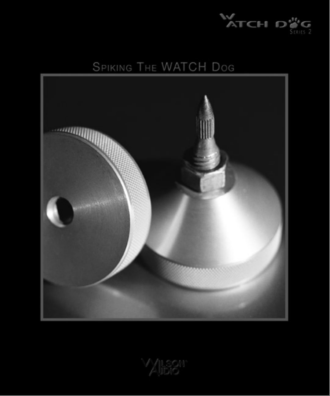
Section 7.0 - WATCH Dog Spikes
The WATCH Dog comes with a set of heavy duty spikes that provide acoustical
isolation as well as optimal height placement for your WATCH Dog. Brass disks that fit
beneath the spikes are included for installations where spikes might damage the floor
surface (such as wood floors).
After determining the WATCH Dog’s position, assemble the spikes as follows:
Assembly
1. Insert threaded bolts in the bolt holes in the front of the subwoofer until they
are flush with the inner surface visible through the acoustic port. Make sure
the Allen key end is facing downward.
2. Screw the acoustical diode onto the bolt until it fits snugly against the bot-
tom of the WATCH Dog. Do not overtighten.
4. Screw the spike (with nut) all the way in until it just touches the bolt. Do not
tighten the nut at this time.
5. Repeat steps 1 through 4 with the other spikes.
6. Using a bubble level, adjust the spikes so that the WATCH Dog is level and
so that all of the spikes are making equal contact with the hard surface
beneath.
The spikes, installed properly, discouple the WATCH Dog from the floor, reducing resonances within the room. They also provide a stable platform for the WATCH
Dog to launch bass energy into the room. The result is cleaner, faster, more dynamic
bass, with improved extension and linearity.
63
Page 64

Page 65

Page 66

66
Page 67

Controlling the WATCH Dog
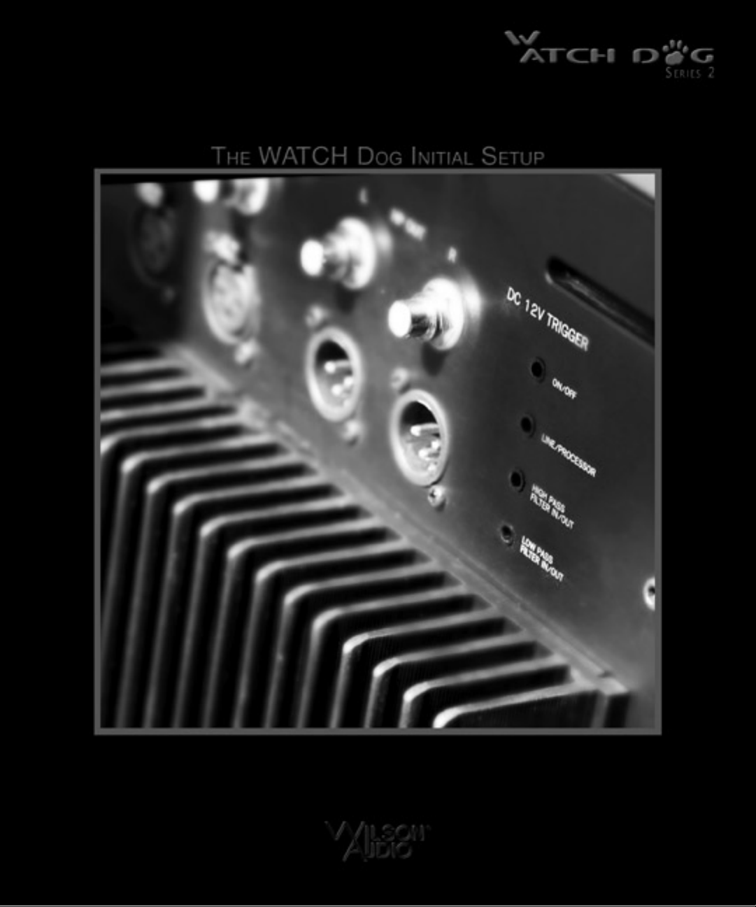
Section 8.0 - Twelve-Volt Trigger Controls
Certain features of the WATCH Dog are controllable via a series of twelve-volt
triggers. This allows remote control access of
these features by outside control systems,
Audio/Video Controllers, etc. This provides
more convenient and seamless operation of the
WATCH Dog within home theaters and complex audio systems.
The twelve-volt triggers are connected
via standard DC ports located adjacent to the
audio inputs on the rear of the WATCH Dog.
The following features can be switched
between two states: On/Off (Stand By);
Line/Processor; High Pass Filter In/Out; Low
Pass Filter In/Out.
To access control of one of these four
features via its twelve-volt trigger, move the
switch corresponding to that function to the
“Rem” position. The switches for
Line/Processor, High Pass Filter In/Out, and
Low Pass Filter In/Out are located on the main
control panel. The switch for the Stand By
On/Off Feature is located on the rear of the
subwoofer. When a function switch is in the
“Rem” position, that feature can only be controled through the twelve-volt trigger.
Please Note: Only the switches relevant to the features to be remote controlled
should be switched to the “Rem” position.
Figure 12
67
Page 68

Toggling the switch to the
remote position without a
twelve volt trigger connected
to that switch will potentially
result in your WATCH Dog
being improperly configured.
The trigger switch defaults
to the zero volt position with
nothing connected.
The trigger is designed
be attached to two-state, relay
switches which toggle
between zero volts and twelve
volts. Several Audio/Video
controllers feature twelve-volt
relay triggers, the status of
which are associated with
selected modes. These can be
68
Figure 14
Figure 13
used in conjunction with the WATCH
Dog relay switches to configure your
subwoofer ideally for those corresponding modes. Similarly, control
systems such as Crestron, AMX and
others have the option for interfacing
with controllable devices via twelvevolt relay triggers. Consult your
audio specialist or installer for more
details.
The twelve-volt triggers are
two-state switches: the presence of
zero volts (no voltage) on the input of
Page 69

Controlling the WATCH Dog - Continued
Twelve Volt Trigger Switch Table
the trigger switches to one state and the presence of twelve volts on the input, the
other. The following table outlines the trigger state of the controllable features of the
WATCH Dog:
Feature Zero Volt Twelve Volt
On/Off (Stand By) Off Stand By On
Line/Processor Input Processor Line
High Pass In/Out High Pass engaged High Pass Bypassed
Low Pass In/Out Low Pass engaged Low Pass Bypassed
69
Page 70

Page 71

Page 72

72
Page 73

Care of the Finish
Section 9.0 - Care of Your WATCH Dog
Your WATCH Dog subwoofer enclosure is hand-painted with WilsonGloss™
paint and hand-polished to a high luster. While the paint seems quite dry to the touch,
final curing and complete hardening takes place over a period of several weeks. To
protect the finish of the WATCH Dog during final manufacturing, shipment, and setup
in your listening room, we have applied a removable layer of protective film over the
painted surface. We recommend that this film be left in place during the positioning
process to prevent damage to the painted surface of your subwoofer. Once you have
determined the WATCH Dog’s final position, remove the film by peeling it off. Do not
leave this film on indefinitely as it will leave impressions on the paint.
It is important that the delicate paint finish of the WATCH speakers be dusted
carefully with the dust cloth, which has been provided. We recommend that the following procedure be observed when dusting the speakers:
• Blow off all loose dust.
• Using the dust cloth as a brush, gently whisk off any remaining
loose dust.
• Shake out the dust cloth.
• Dust the finish, using linear motions in one direction parallel to the
floor. Avoid using circular or vertical motions.
Because the paint requires a period of several weeks to fully cure, we recommend that no cleaning fluids, such as glass cleaners, be used during this initial period
of time. When the paint is fully cured, heavy finger prints and other minor smudges
may be removed with a glass cleaner. When cleaning the painted surface of your subwoofer, always use the dust cloth. Stronger solvents are not recommended under any
circumstances as they may damage the paint. Consult your dealer for further information if required.
Periodic polishing may be desired over the years to maintain the high luster of
the finish. We recommend a nonabrasive, carnauba-based wax and a soft cloth.
73
Page 74

Several pieces of the Center channel are made of black “X” material. Where
this material is not painted, it will require periodic polishing to maintain the semigloss
finish. We recommend a silicone-based plastic polish (available at automotive supply
stores).
74
Page 75

Care of the Finish - Continued
75
Page 76

Page 77
Page 78

78
Page 79

Specifications
Port: Front Firing
Frequency Response: 20-30/150Hz Adjustable
Low Pass Filter: Level adjustable, switchable in/out; 12dB/octave or 18dB/octave
High Pass Filter: Switchable in/out; 6dB/out; or 12dB/octave
Phase: Continuously variable from 0-180 degrees
EQ: Switchable in/out, +10dB boost to -10dB cut; variable Q from .2 to 2; variable fre-
quency selector from 30 to 150Hz
Finish: Standard Wilsongloss finishes, Custom finishes available at additional cost
Amplifier:
Power: 400 Watts
Input Impedance: 56 K ohms single ended, 4 K ohms balanced
Inputs: Balanced and single ended for Right, Left and Processor/LFE
Outputs: Balanced and single ended for Right, Left, High Pass filter outputs
Drive Unit: 12 inch long throw
Height: 27 1/2 inches
Width: 18 inches
Depth: 27 1/2 inches (add 3 1/2 inches for grill & heat sink)
Approx. Product Weight: 283 lbs
79
Page 80

Page 81

Page 82

82
Page 83

Wilson Audio
LI
Limited Warranty
Terms & Conditions
Limited Warranty
Subject to the conditions set forth herein, Wilson Audio warrants its loudspeakers to be free of manufacturing defects in material and workmanship for the Warranty
Period. The Warranty Period is a period of 90 days from the date of purchase by the
original purchaser, or if both of the following two requirements are met, the Warranty
Period is a period of five (5) years from the date of purchase by the original purchaser:
Requirement No. 1. No later than 30 days after product delivery to the
customer, the Warranty Registration Form must have been returned by the
customer to Wilson Audio;
Requirement No. 2. The product must have been professionally installed
by the Wilson Audio dealer that sold the product to the customer.
FAILURE TO COMPLY WITH EITHER REQUIREMENT NO. 1 OR REQUIREMENT NO. 2 WILL RESULT IN THE WARRANTY PERIOD BEING LIMITED TO A PERIOD OF 90 DAYS ONLY.
Conditions
This Limited Warranty is also subject to the following conditions and limitations.
The Limited Warranty is void and inapplicable if the product has been used or handled
other than in accordance with the instructions in the owner’s manual, or has been
abused or misused, damaged by accident or neglect or in being transported, or if the
product has been tampered with or service or repair of the product has been attempted or performed by anyone other than Wilson Audio, an authorized Wilson Audio
83
Page 84

Dealer Technician or a service or repair center authorized by Wilson Audio to service
or repair the product. Contact Wilson Audio at (801) 377-2233 for information on location of Wilson Audio Dealers and authorized service and repair centers. Most repairs
can be made in the field. In instances where return to Wilson Audio’s factory is
required, the dealer or customer must first obtain a return authorization. Purchaser
must pay for shipping to Wilson Audio, and Wilson Audio will pay for shipping of its
choice to return the product to purchaser. A RETURNED PRODUCT MUST BE
ACCOMPANIED BY A WRITTEN DESCRIPTION OF THE DEFECT. Wilson Audio
reserves the right to modify the design of any product without obligation to purchasers
of previously manufactured products and to change the prices or specifications of any
product without notice or obligation to any person.
Remedy
In the event that the product fails to meet the above Limited Warranty and the
conditions set forth herein have been met, the purchaser’s sole remedy under this
Limited Warranty shall be to: (1) contact an authorized Wilson Audio Dealer within the
Warranty Period for service or repair of the product without charge for parts or labor,
which service or repair, at the Dealer’s option, shall take place either at the location
where the product is installed or at the Dealer’s place of business; or (2) if purchaser
has timely sought service or repair and the product cannot be serviced or repaired by
the Dealer, then purchaser may obtain a return authorization from Wilson Audio and at
purchaser’s expense return the product to Wilson Audio where the defect will be rectified without charge for parts or labor.
Warranty is Limited to Original Purchaser
This Limited Warranty is for the sole benefit of the original purchaser of the covered product and shall not be transferred to a subsequent purchaser of the product,
unless the product is purchased by the subsequent purchaser from an authorized
Wilson Audio Dealer who has certified the product in accordance with Wilson Audio
standards and requirements and the certification has been accepted by Wilson Audio,
84
Page 85

in which event the Limited Warranty for the product so purchased and certified shall
expire at the end of the original Warranty Period applicable to the product.
Demonstration Equipment
Equipment, while used by an authorized dealer for demonstration purposes, is
warranted to be free of manufacturing defects in materials and workmanship for a
period of five (5) years from the date of shipment to the dealer. Demo equipment
needing warranty service may be repaired on-site or, if necessary, correctly packed
and returned to Wilson Audio by the dealer at dealer’s sole expense. Wilson Audio will
pay return freight of its choice. A returned product must be accompanied by a written
description of the defect. Dealer owned demonstration equipment sold at retail within
two (2) years of date of shipment to the dealer is warranted to the first retail customer
to be free of manufacturing defects in materials and workmanship for the same time
periods as if the product had originally been bought for immediate resale to the retail
customer. Wilson Audio products are warranted for a period of 90 days, unless
extended to 5 years, as provided above, by return and filing of completed Warranty
Registration at Wilson Audio within 30 days after product delivery to customer and the
product was professionally installed by the Wilson Audio Dealer that sold the product
to the customer.
Miscellaneous
ALL EXPRESS AND IMPLIED WARRANTIES NOT PROVIDED FOR HEREIN ARE
HEREBY EXPRESSLY DISCLAIMED. ANY LEGALLY IMPOSED IMPLIED WARRANTIES RELATING TO THE PRODUCT SHALL BE LIMITED TO THE DURATION OF
THIS LIMITED WARRANTY. THIS LIMITED WARRANTY DOES NOT EXTEND TO ANY
INCIDENTAL OR CONSEQUENTIAL COSTS OR DAMAGES TO THE PURCHASER.
Some states do not allow limitations on how long an implied warranty lasts or an
exclusion or limitation of incidental or consequential damages, so the above limitations or exclusions may not apply to you. This Limited Warranty gives you specific
legal rights, and you may also have other rights, which vary, from state to state.
85
Page 86

86
Page 87

87
 Loading...