

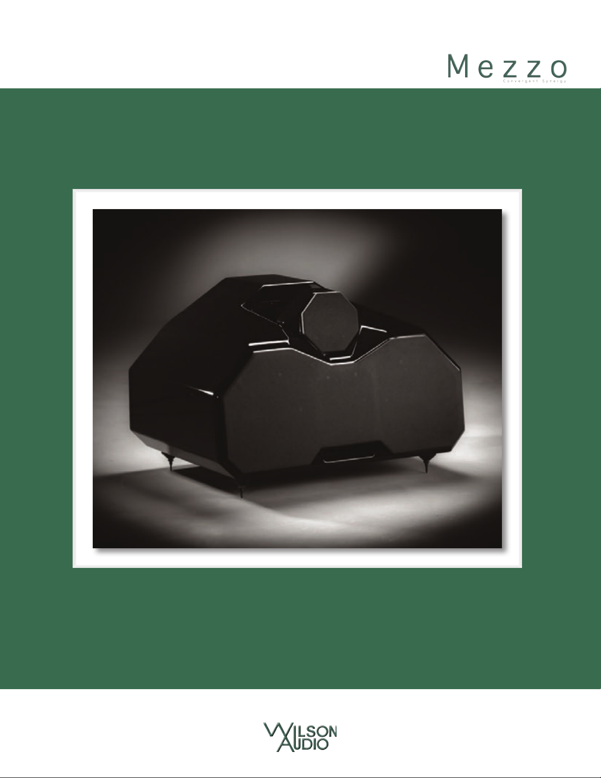
Page 1
Page 2
Page 3
Page 4
Page 5
Page 6
Page 7
Section 1—Introduction
.
Page 8

.
Page 9

S e C T i O n 1 . 1 — M e z z O C O n v e r g e n T S y n e r g y i n T r O d u C T i O n
.
Section 1.1—Mezzo Convergent Synergy Introduction
From all of us at Wilson Audio Specialties—thank you for purchasing the Mezzo Con-
vergent Synergy loudspeaker. The information contained within the pages of this manual
will inform and instruct on the proper assembly, set up, and long term care of your Mezzo
Convergent Synergy.
The original Mezzo™ was formulated and engineered with a specific function in
mind: a loudspeaker that possessed the sonic signature of the Wilson’s Sasha W/P®, but in
a low-profile package. When used as a center channel, the Mezzo seamlessly matched the
acoustic signature of Wilson’s original Sasha. Indeed, the Mezzo featured a driver comple-
ment identical to the Sasha, with the exception of the midrange driver, which was borrowed
from the legendary Alexandria XLF®. The Mezzo also provided an unprecedented level of
musical accuracy in music systems and home theaters where its low-profile form solved ar-
chitectural challenges, such as in those installations where a tall loudspeaker would block
wall-to-wall cinema screens, the view afforded by large windows, or wall-hanging artwork.
Whether it was used as a center channel in conjunction with Sasha, MAXX, or Alexandria,
or as a main loudspeaker, Mezzo matched the tonal beauty, dynamic speed, tonal sophisti-
cation, resolution, and sense of “thereness” that were hallmarks of the original Sasha W/P.
With the advent of Wilson’s Convergent Synergy tweeter in the Alexandria XLF, the
Alexia, and now the Sasha W/P Series-2, it quickly became apparent that a Convergent
Synergy tweeter version of the Mezzo was needed.
Among the technical innovations of the Mezzo Convergent Synergy:
The Mezzo Convergent Synergy sources its midrange driver directly from the ground-
breaking Wilson Alexandria XLF. With this midrange driver, Dave and the Wilson engineers
set out to redefine what was possible in cone midrange technology—and to capture cer-
tain qualities of live music heretofore not achieved in any other design. Their efforts were
rewarded. The result was the Wilson midrange driver. One has to hear the clarity, tonal
Wilson Audio Specialties
9
Page 10

M e z z o C o n v e r g e n t S y n e r g y o w n e r ’ S M a n u a l
.
density and truthfulness, and dynamic clarity to appreciate the resulting vast improvement
in the midrange over other designs.
The original version of Wilson Audio’s Convergent Synergy tweeter was developed in
conjunction with the Alexandria XLF. It now makes its debut in a new custom form, spe-
cifically designed to meet the needs of the Mezzo Convergent Synergy’s mission. During
the development of the Convergent Synergy tweeter, Dave and the engineers tested a wide
spectrum of tweeters fabricated with exotic materials such as diamond and beryllium. Each
have their own unique qualities and virtues. Many exhibit flat frequency response, or are
extended several octaves above the audible bandwidth. But none matched the dynamic
contrast and harmonic expression of Wilson’s existing titanium design. But most impor-
tantly, none of them were an ideal match to our midrange driver. The Convergent Synergy
tweeter rejects exotic materials in favor of a uniquely constructed silk dome design. With
the Convergent Synergy driver, the design requirement of ultra-low distortion and very
robust power handling down in the lower part of its range are beautifully met. These quali-
ties converge with a much higher resonant frequency and flatter frequency response when
compared to the original inverted titanium design. Wilson’s Convergent Synergy tweeter
is extremely linear. It crosses over synergistically to Wilson’s midrange driver. The noise
floor is much lower than the titanium driver it replaces. The Mezzo Convergent Synergy
crossover features technology that accounts for the formidable performance envelope of-
fered by the Convergent Synergy tweeter.
The Convergent Synergy tweeter’s acoustic and mechanical demands are somewhat
different from the titanium tweeter it replaces. Using the latest version of Wilson’s propri-
etary composite, X-material, Wilson’s engineers designed an all new tweeter module. The
module is extremely inert and non-resonant. It also accounts for the Convergent Synergy
tweeter’s dispersion characteristics. Great care was taken to address diffraction—a type of
time-domain distortion that results from reflections off the speaker cabinet. The shape of
10
Wilson Audio Specialties
Page 11

S e C T i O n 1 . 1 — M e z z O C O n v e r g e n T S y n e r g y i n T r O d u C T i O n
.
the module is emblematic of this effort, as is the shape and material of the energy-absorbing pad
that surrounds the tweeter.
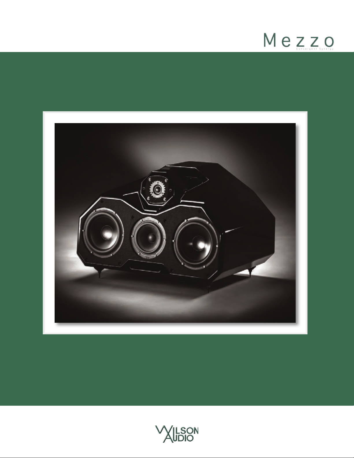
Sasha W/P Series 2 woofer. The Mezzo Convergent Synergy sources its woofer di-
rectly from the Sasha W/P Series 2. The speed, dynamic alacrity, and tunefulness that are
all distinctive features of the latest Sasha are in evidence here in similar proportions.
In the main module, Mezzo Convergent Synergy’s two woofers are mounted horizon-
tally, flanking the midrange driver. Achieving near perfect driver-alignment at the listening
position requires the adjustability of the tweeter by changing its relative position in rela-
tion to the midrange and woofer drivers, such that all drivers’ acoustic centers are equidis-
tant from the listener. The tweeter module is adjustable via a provided chart according to
ear height and listening distance—and for a variety of Mezzo Convergent Synergy instal-
lation strategies. Whether the Mezzo Convergent Synergy is installed directly on the floor,
on one-of-two custom designed stands, or in custom cabinets, the Mezzo Convergent Syn-
ergy’s drivers can be properly aligned to accommodate these scenarios.
Just as in the Sasha, the Mezzo Convergent Synergy uses an “S” Material midrange
baffle. S-material is a relatively new enclosure composite designed in conjunction with the
Sasha W/P. The S-material baffle reduces measurable and audible noise and coloration in
the critical midrange. Wilson’s proprietary X-material is used in the balance of the enclo-
sure walls, continuing Wilson’s practice of building ultra-low resonance cabinets.
Two stands: The Hourglass Stand features a solid front plinth, which allows for 2π Ste-
radian support of the midrange and woofer drivers, resulting in more linear and impactful
performance in the upper bass and lower midrange. The second optional stand features
an pedestal, which can be customized for overall height; the Mezzo can be optimized for
the specifics of center channel placement in relationship to large cinema screens.
More on Propagation delay
A musical waveform is a complex overlay of frequencies, amplitudes, and phase
Wilson Audio Specialties
11
Page 12

M e z z o C o n v e r g e n t S y n e r g y o w n e r ’ S M a n u a l
.
relationships. With current technology, no single transducer can reproduce the full range
of music at realistic sound pressure levels while maintaining consistent dispersion. The
solution is the multiple driver array, with specific drivers dedicated to various portions
of the frequency range. Multiple drivers introduce their own set of problems. A challenge
typically ignored by speaker designers is preserving the precise time relationships of the
leading edge of the musical waveform.
The key to solving this problem lies in Wilson’s innovative and patented Adjustable
Propagation Delay technology, which employs movable modules that allow the individual
adjustment of the drivers in the time domain. Using this technology, each driver’s wave-
form propagation “matches up” with the other drivers in the system in such a way as to
create the sonic equivalent of a single point source. There are certain loudspeaker makers
other than Wilson that recognize the need to correctly align their drivers, but they do so
for only one theoretical listening position.
The fact is, misalignment of the drivers by fractions of an inch will audibly degrade
transient accuracy, soundstage height, depth, and width. Misalignment of the drivers will
also introduce tonal anomalies that destroy the otherwise convincing “presence” of an in-
strument or a singer’s voice. Wilson’s solution for propagation delay correction has long
set the standard for precise driver positioning in order to insure correct time-alignment for
a wide range of real room listening distances and ear heights.
The Mezzo Convergent Synergy cabinet is a further evolution of Wilson’s philosophy
that truly great forms follow a corresponding function. It is a visual metaphor for the solu-
tion Wilson Audio pioneered to address issues of phase coherence exacerbated by large
speaker systems. Typical of the creative process, the solution itself is an analogy to the
field of optics and the design of wide-angle lenses. The means of maintaining edge-to-edge
sharpness at both close and far focusing distances for a high quality wide-angle lens sug-
gested a solution to the similar problem of time domain accuracy for large speaker systems
12
Wilson Audio Specialties
Page 13
S e C T i O n 1 . 1 — M e z z O C O n v e r g e n T S y n e r g y i n T r O d u C T i O n
.
at both near and far listening positions.
With Mezzo Convergent Synergy, Wilson Audio takes this concept a logical step
further, addressing the issue of optimal driver dispersion in the large cabinet system. Ideal
driver dispersion for both near and far listening positions requires the drivers be adjust-
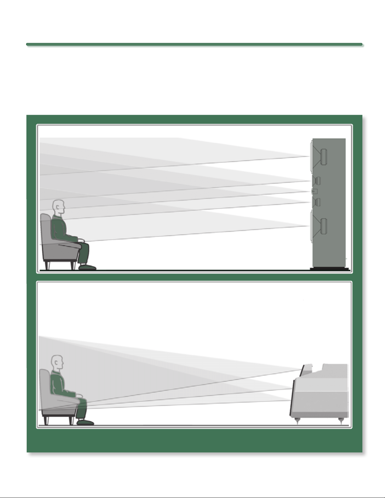
Fi gu re 1a - typi ca l loudS pe ak erS e xh ib it le SS th an o pt iMu M
pr opa gatio n d el ay and d iS pe rSi on c ha rac te ri Sti cS . th e S ou nd
qu al ity i S co Mpr oM iS ed Fo r al l l iS te nerS in a ll ro oM S.
Fi gu re 1b - aSph er ic al pr opa gat io n del ay op tiM iz eS d riv er /r ooM
in te racti on F or a vari et y oF Si tu ati on S. th iS p rov id eS conS iS te ntly
op ti Miz ed r eS ultS i n a Wi de ra ng e o F ro oM S a nd l iSten in g poS it io nS .
fi gur e 1 – us in g t ec hno log Y fro M sas ha, Mezz o con Ver ge nt sYn er gY’s gro up de laY is co r-
re cte d in the t iMe d oMa in�
Wilson Audio Specialties
13
Page 14

M e z z O C O n v e r g e n T S y n e r g y O w n e r ’ S M a n u a l
.
able.
With the Mezzo Convergent Synergy, you and others you listen with, will hear your
favorite recordings and soundtracks with true time coherency, full frequency range, unfet-
tered dynamics, and vanishingly low distortion. The improvement in realism wrought by
Mezzo Convergent Synergy is delightfully revolutionary.
14
Wilson Audio Specialties
Page 15
Section 2—Uncrating
.
Page 16

.
Page 17

S e C T i O n 2 . 1 — u n C r a T i n g T h e M e z z O C O n v e r g e n T S y n e r g y
.
Section 2.1—Uncrating the Mezzo Convergent Synergy
Initial Check
The Mezzo Convergent Synergy is shipped in a wooden crate. Upon receiving your
Mezzo Convergent Synergy, please check the crate’s condition. If the crate is damaged,
please report it to the shipping company immediately for insurance verification.
The following items are recommended for this procedure:
• Electric Screwdriver
• Phillips head drive bit
• Masking tape (for use in speaker setup)
Uncrating the Mezzo Convergent Synergy
A minimum of two strong adults is required to set up the Mezzo Convergent Synergy.
1. With the crate lid facing up, unscrew the wood screws securing the lid. Remove the lid.
2. One crate will contain the tool kit.
3. The Mezzo Convergent Synergy is shipped with casters installed. Carefully
lift the crate upright so that the Mezzo is now vertical. With the Mezzo’s
bottom toward the floor and one person holding the crate, the second person
should reach in and gently roll the Mezzo out of the crate, carefully, so as
not to hit the Mezzo on the crate and scratch the paint.
Section 2.2—Crate Content Checklist
Now that you have unpacked your Mezzo Convergent Synergy, you can inventory all
the additional items in the crate.
Wilson Audio Specialties
17
Page 18

M e z z o C o n v e r g e n t S y n e r g y o w n e r ’ S M a n u a l
.
Mezzo Convergent Synergy Crate
1—Owner’s Manual
1—Warranty Registration (included in the manual)
1—Mezzo Convergent Synergy Midrange/Woofer Grill
1—Mezzo Convergent Synergy Tweeter Grill
4—Nuts
4—Spikes
4—Brass Discs
4—Spacers
4—Diodes
1—Universal Allen Handle
1—1/2” Nut Driver
1—1/8” Allen Head
1—3/16” Allen Head
1—3/32” Allen Head
1—5/32” Allen Head
1—5/16” Allen Head
18
4—3/8” - 16 x 1 1/2” Set Screws
Wilson Audio Specialties
Page 19
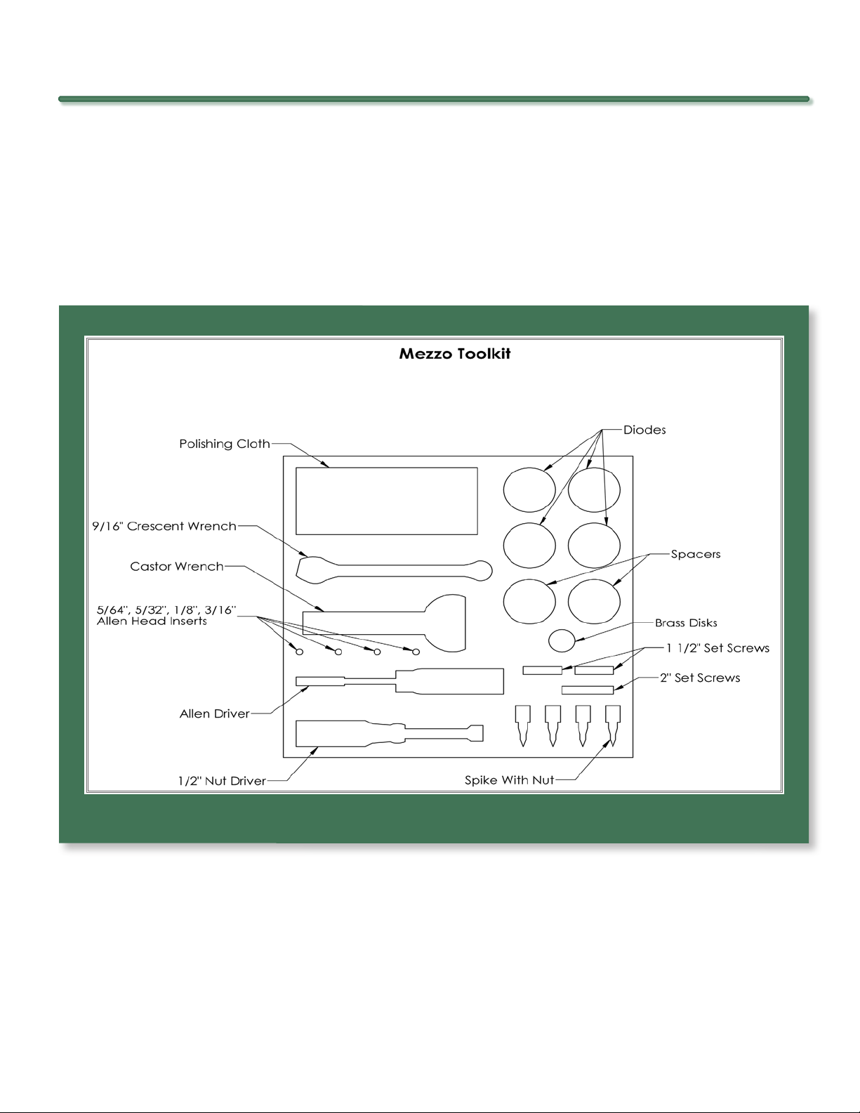
2—3/8” - 16 x 2” Set Screws
.
1—Blue Polishing Cloth
1 – Caster Wrench
1—9/16” Wrench
S e C T i O n 2 . 2 — C r a T e C O n T e n T C h e C k l i S T
fi gur e 2 – Me zz o con Ver gen t sYn er g Y
Mezzo Convergent Synergy Stand Box (Pedestal Stand)
If you purchased a Wilson Audio Mezzo Convergent Synergy Stand on which to
mount your Mezzo Convergent Synergy, you will find the following items in the box with
your stand:
Wilson Audio Specialties
19
Page 20

M e z z O C O n v e r g e n T S y n e r g y O w n e r ’ S M a n u a l
.
4—3/8” - 16 x 1 1/2” Socket Head Cap Screws
4—3/8” x 7/8” Stainless Steel Flat Washers
1—5/16” Long Arm Allen Wrench
1—Polishing Cloth
20
Wilson Audio Specialties
Page 21
Section 3—In Your Room
.
Page 22

.
Page 23

S e C T i O n 3 . 1 — T h e w i l S O n a u d i O S e T u p p r O C e d u r e
.
Section 3.1—The Wilson Audio Setup Procedure
You are surely excited about setting up your Mezzo Convergent Synergy and doing
some listening, but before you begin, we would like to discuss some of the important room
acoustical information that will help you set up your loudspeakers properly.
Final Listening Room Setup (Voicing)
For Mezzo Convergent Synergy’s size and single-module configuration, it is unmatched
in its ability to reproduce the musical event. However, room acoustics and boundary in-
teractions affect the sound of a loudspeaker to such a large degree that poor setup can
seriously degrade your enjoyment of even the finest loudspeaker.
Therefore, we offer the following section, which will present some guidelines on
room acoustics and their interactions with loudspeakers. While we will also outline some
detailed suggestions on the setup of the Mezzo Convergent Synergy, we strongly suggest
that you have your local Wilson Audio dealer perform the final speaker “voicing” with you.
Wilson dealers are specially trained in setting up Wilson loudspeakers and will ensure that
you realize the full value of your purchase. What follows is an outline of the Wilson Audio
Setup Procedure (WASP). When carefully followed, the process has proven to be the most
effective method for setting up Wilson loudspeakers.
Zone of Neutrality: Main Left and Right Channel
The “Zone of Neutrality” is an area in your room where the speakers will sound most
natural. This location is where the speakers interact the least with adjacent room boundar-
ies. It is important to have a clear working space while determining the Zone of Neutrality.
The following is a simple method to locate the Zone of Neutrality within your listen-
ing environment:
1. Stand against the wall BEHIND the location where you intend to position
your loudspeakers. Speaking in a moderately loud voice and at a constant
Wilson Audio Specialties
23
Page 24

M e z z o C o n v e r g e n t S y n e r g y o w n e r ’ S M a n u a l
.
volume, project your voice out into the room. Your voice will have an overly
heavy, “chesty” quality because of your proximity to the rear wall.
2. While speaking, slowly move out into the room, progressing in a direction
parallel to the sidewall. It is helpful to have another listener seated in the
listening position to assist you during this process. Listen to how your voice
“frees up” from the added bass energy imparted by the rear wall boundary.
Also notice that your voice is quite spatially diffuse (to your assistant, your
voice will sound spatially large and difficult to localize) as you begin to ease
away from the rear wall.
3. At some point during your progression forward into the room, you will observe a sonic transition in your voice; it will sound more tonally correct and
less spatially diffuse (your assistant can now precisely localize the exact origin of your voice). When you hear this transition, you have entered the inner
edge of the Zone of Neutrality. Place a piece of tape on the floor to mark this
location. Although it will vary from room to room, in most rooms the zone
begins between two and a half to three feet from the rear wall.
4. Continue to walk slowly away from the rear wall. After some distance, usually one to two feet past the first piece of tape, you will begin to hear your
voice lose focus and appear to reflect (echo) in front of you. This is caused
by the return of the room’s boundary contribution; your voice is now interacting with the opposite wall. At the point where you begin to hear the
reflected sound of your voice, you have reached the outer edge of the Zone
of Neutrality. Place a piece of tape on the floor and mark this location. The
distance between the “inner” and “outer” edge tape marks is usually between eight inches (for small, interactive rooms) and three feet (for large,
more neutral rooms).
5. Now position yourself against the side wall perpendicular to the intended
speaker location. Stand between the two tape marks. Using the same pro-
24
cedure as above, begin moving into the room toward the opposite sidewall,
progressing between the two pieces of tape. As above, listen for the point in
the room where your voice transitions from bass-heavy and diffuse to neutral. Mark this point with tape. Continue your progression until there is an
Wilson Audio Specialties
Page 25

S e C T i O n 3 . 2 — r O O M a C O u S T i C S
.
obvious interaction with the opposite wall in front of you and mark this point
with tape. The four pieces of tape now form a rectangle that establishes the
Zone of Neutrality for the loudspeaker located on that side of the room. Using the four marks as your guide, tape an outline to define the boundaries of
the rectangle.
6. Repeat this process for each speaker location individually. These are your
Zones of Neutrality, one for each channel.
Theoretically, the Zone of Neutrality for any room runs like a path, parallel to the
walls all around the room. Adjacent to very large windows and open doors, the outer edge
of the Zone of Neutrality moves closer to the wall and becomes wider. If you were to ex-
tend the inner and outer boundaries of the Zone for the sidewalls and the front wall (be-
hind the speakers), they would intersect. After you complete this procedure for the other
loudspeaker, you will now have two rectangles, one on the floor on either side of the room.
Section 3.2—Room Acoustics
Note: The following section contains general information on room acoustics and loudspeaker/room interaction. The concepts outlined below are equally relevant when dealing with multi-channel audio or home theater. The careful application of these concepts,
as you evaluate the acoustical characteristics of your own room configuration, will allow you to optimize the performance of your Mezzo Convergent Synergy.
Slap Echo
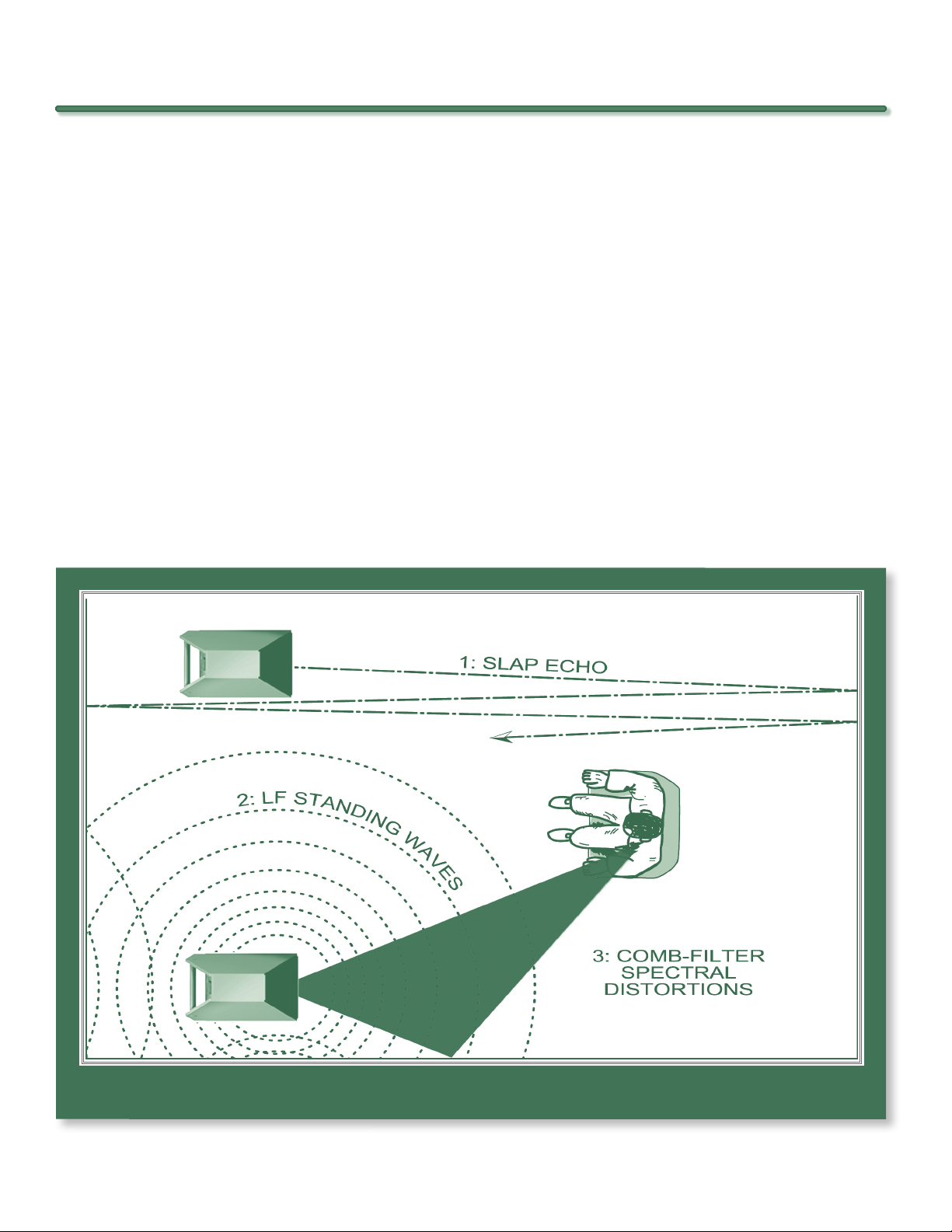
Probably the most obnoxious form of reflection is called “slap echo.” With slap-echo,
primarily midrange and high frequency sounds reflect off of two parallel hard surfaces. The
sound literally reverberates back and forth until it is finally dissipated over time. You can
test for slap echo in any room by clapping your hands sharply in the middle of the room
and listening for the characteristic sound of the echo in the midrange. Slap echo destroys
the sound quality of a stereo system in two ways:
Wilson Audio Specialties
25
Page 26
M e z z o C o n v e r g e n t S y n e r g y o w n e r ’ S M a n u a l
.
• It adds harshness to the upper midrange and treble by storing time-domain
smearing energy.
• It destroys the delicate phase relationships, which help to establish an accurate soundstage.
Slap echo (see Figure 3) is a common acoustical problem in the typical domestic lis-
tening room because most of these rooms have walls with a hard, reflective nature, only
occasionally interrupted by curtains, wall art, or drapes. The best (but least practical)
solution to eliminate slap echo is nonparallel walls. This is because, rather than support
slap-echo, nonparallel walls allow the sound to diffuse. This approach can be accounted
for during the construction process. For existing rooms, slap echo can also be controlled
entirely by the application of absorptive materials to the hard surfaces. These are absorp-
fi gur e 3 – co MM on ro oM ref le cti on pr obl eM s
26
Wilson Audio Specialties
Page 27

S e C T i O n 3 . 2 — r O O M a C O u S T i C S
.
tive materials that can be used to ameliorate slap echo:
• Illbruck Sonex®
• Air duct board
• Large ceiling to floor drapes
• Carpeting to wall surfaces
In many domestic listening environments, heavy stuffed furnishings reduce slap echo
somewhat. Unfortunately, their effectiveness is not predictable. Diffusers are sometimes
also used to very good subjective effect, particularly in quite large rooms. Sound absor-
bent materials such as described above will alter the tonal characteristic of the room by
making it sound “deader,” less “bright and alive,” and “quieter.” These changes usually
make the room more pleasant for conversation, but sometimes render it too dull in the high
frequencies to be musically involving. Soundtrack effects will be more localized. However,
over-damping the room skews the tonal balance unnaturally toward the bass, and also com-
presses dynamics, robing the system of musical life excitement.
Diffusers, on the other hand, do not affect the tonal balance characteristic of the
room as much. Placed properly, diffusers create a smoother and more open sound. Some
diffusers, due to their construction, create narrow midrange peaks and suck out the warmth
region. Do not use diffusers on the wall behind the speakers or on the sidewalls directly
beside the speakers. It is our experience that all of these room treatment devices should
be used judiciously.
Standing Waves
Another type of reflection phenomenon is “standing waves.” Standing waves cause
the unnatural boosting or accentuation of certain frequencies, typically in the bass, to be
Wilson Audio Specialties
27
Page 28

M e z z o C o n v e r g e n t S y n e r g y o w n e r ’ S M a n u a l
.
found at certain discreet locations in the room. These locations differ according to room
dimension and size. A room generating severe standing waves creates difficulty in setup. In
these rooms, the speaker will sound radically different as it is moved around. The effects
of standing waves on a loudspeaker’s performance are primarily in the areas listed.
• Tonal balance
• Resolution of low-level detail
• Soundstaging
Standing waves are more difficult to correct than slap echo because they tend to oc-
cur at a lower frequency. Absorbent materials, such as Illbruck Sonex®, are ineffective at
controlling reflections in the bass region. Moving speakers about slightly in the room is, for
most people, their only control over standing waves. Sometimes a change of placement of
as little as two or three inches can dramatically alter the tonal balance of a small system.
Fortunately, minor low frequency standing waves are well controlled by positioning
ASC Tube Traps™ in the corners of the room. Very serious low frequency accentuation
usually requires a custom-designed bass trap system.
Low frequency standing waves can be particularly troublesome in rooms constructed
of concrete or brick. These materials trap the bass in the room unless it is allowed to leak
out of the room through windows and doors.
In general, placement of the speaker in a corner will excite the maximal number of
standing waves in a room and is to be avoided for most direct radiator, full-range loud-
speaker systems. Some benefit is achieved by placing the stereo pair of loudspeakers
slightly asymmetrically in the listening room. This is so the standing waves caused by the
distance between one speaker and its adjacent walls and floors are not the same as the
standing wave frequencies excited by the dimensions in the other channel.
28
Wilson Audio Specialties
Page 29

S e C T i O n 3 . 3 — r e S O n a n C e S
.
Comb Filter Effect
The “comb filter” effect is a special type of standing wave noticeable primarily at
higher frequencies and shorter wavelengths.
Acoustical comb filtering occurs when sound from a single source, such as a loud-
speaker, is directed toward a microphone or listener from a distance. The first sound to
reach the microphone is the direct sound, followed by a delayed, reflected sound. At cer-
tain frequencies, cancellation occurs because the reflected sound lags in phase relative
to the direct sound. This cancellation is most apparent where the two frequencies are 180
degrees out of phase. Further, there is augmentation at other frequencies where the direct
and the reflected sounds arrive in phase. Because it is a function of wavelength, the comb
filter effect will notch out portions of the audio spectrum at linearly spaced intervals. Sub-
jectively, comb filter effect evidences itself as follows:
• Added roughness to the sound
• Reduction of harmonic richness
• Smearing of lateral soundstage image focus and placement
Comb filter effects are often caused by side wall reflections. They are best controlled
by very careful speaker placement and by the judicious placement of Illbruck Sonex® or
air duct panels applied to that part of the wall where the reflection occurs.
Section 3.3—Resonances
Resonance in listening rooms is generally caused by two sources:
• Structures within the listening room.
• The volume of air itself within the listening room.
Wilson Audio Specialties
29
Page 30

M e z z o C o n v e r g e n t S y n e r g y o w n e r ’ S M a n u a l
.
Structural Resonance
Structural resonances are familiar to most people as buzzes and rattles, but this type
of resonance usually only occurs at extremely high volume levels and is usually masked by
the music. In many wood frame rooms the most common type of structural resonance prob-
lem is “booming” of walls and floors. You can test for these very easily by tapping the wall
with the palm of your hand or stomping on the floor. Most rooms exhibit mid-bass “boom”
when struck. The loudspeaker playing in the room also excites these resonances. To give
you an idea of what the perfect wall would sound like, imagine rapping your hand against
the side of a mountain. Structural wall resonances generally occur in the low to mid-bass
frequencies and add a false fullness to the tonal balance. They, too, are more prominent
at louder levels, but their contribution to the sound of the speaker is more progressive.
Rattling windows, picture frames, lamp shades, etc., can generally be silenced with small
pieces of caulk or with blocks of felt. However, short of actually adding additional layers
of sheet rock to flimsy walls, there is little that can be done to eliminate wall resonances.
Volume Resonance
The physical dimensions and volume of air in a room will also support standing wave
modes and resonances at frequencies determined by the size of that room. Larger rooms
will resonate at a lower frequency and have more complex (better) modal distributions
than will smaller rooms. Volume resonances, wall panel resonances, and low frequency
standing waves combine to form a low frequency coloration in the sound. At its worst, it is
a grossly exaggerated fullness, which tends to obscure detail and distort the natural tonal
balance of the speaker system.
Occasionally, however, there is just enough resonance to give a little added warmth
to the sound – an addition some listeners prefer. Careful placement of loudspeakers in the
room can dramatically reduce the speakers’ destructive interaction with low frequency
modes. ASC Tube Traps™ are effective in reducing some of this low frequency room col-
30
Wilson Audio Specialties
Page 31

S e C T i O n 3 . 4 — y O u r r O O M
.
oration. Custom designed bass traps, such as perforated Helmholtz resonators, provide the
greatest degree of low frequency control.
Section 3.4—Your Room
Room Shapes
Standing waves are pressure waves propagated by the interaction of sound and op-
posing parallel walls. This interaction creates patterns of low and high acoustical pressure
zones that accentuate and attenuate particular frequencies. Those frequencies are depen-
dent on room size and dimension.
There are three basic shapes for most rooms: square, rectangular, and L-shaped (see
Figure 4).
A perfectly square room is the most difficult room in which to set up speakers. By vir-
tue of its shape, a square room is the perfect medium for building and sustaining standing
waves. These rooms heavily influence the music played by loudspeakers, greatly diminish-
ing the listening experience.
Long, narrow, rectangular rooms also pose their own special acoustical problems for
speaker setup. They have the ability to create several standing wave nodes, which will have
different standing wave frequency exaggerations depending on where you are sitting. Ad-
ditionally, these long rooms are often quite lean in the bass near the center of the room.
Rectangular rooms are still preferred to square rooms because, by having two sets of dis-
similar length walls, standing waves are not as strongly reinforced and will dissipate more
quickly than in a square room. In these rooms, the preferred speaker position for spatial
placement and midrange resolution would be on the longer walls. Bass response would be
reinforced by speaker placement on the short walls.
In many cases, L-shaped rooms (see Figure 4) offer the best environment for speaker
setup. Ideally, speakers should be set up along the primary (longest) leg of the room. They
Wilson Audio Specialties
31
Page 32

M e z z o C o n v e r g e n t S y n e r g y o w n e r ’ S M a n u a l
.
fi gur e 4 – po ss ibl e lou dsp ea ker pl ac eMe nt wi thi n Var io us roo M sha pe s
should fire from the end of the leg (short wall) toward the L, or they should be along the
longest wall. In this way, both speakers are firing the same distance to the back wall. The
asymmetry of the walls in L-shaped rooms resists the buildup of standing waves (see Figure
4).
Speaker Placement Versus Listening Position
The location of your listening position is as important as the careful setup of your
Wilson Audio loudspeakers. The listening position should ideally be no more than 1.1 to
1.25 times the distance between the tweeters on each speaker. Therefore, in a long, rect-
angular room of 12’ x 18’, if the speaker tweeters are going to be 9’ apart, you should be
sitting 9’11’’ to 11’3’’ from the speaker. This would be more than halfway down the long
axis of the room.
Many people place the speakers on one end and sit at the other end of the room.
This approach will not yield the finest sound. Carefully consider your listening position.
Our experience has shown that any listening position that places your head closer than 14”
32
Wilson Audio Specialties
Page 33

S e C T i O n 3 . 4 — y O u r r O O M
.
from a room boundary will diminish the sonic results of your listening.
Speaker Orientation
Speaker placement and orientation are two of the most important considerations in
obtaining superior sound. The first thing you need to do is eliminate the sidewalls as a
sonic influence in your system. Speakers placed too close to the sidewalls will suffer from
a strong primary reflection. This can cause out-of-phase cancellations, or comb filtering,
which will cancel some frequencies and change the tonal balance of the music. The Wil-
son Audio Setup Procedure (Section 3.1) is the best method with which to position your
loudspeakers. Start with the speakers about 18” from each wall (as measured from the rear
of the enclosure) and, if you need to move them relative to the side wall, move them away
from the wall, not closer.
A very important aspect of speaker placement is how far from the back wall to place
the speakers. The closer a loudspeaker is to the back wall, the more pronounced the low
bass energy and centering of the image will be. However, this comes at a definite reduction
in stage size and bloom as well as a deterioration of upper bass quality. You must find the
proper balance of these two factors, but remember, if you are partial to bass response or
air and bloom, do not overcompensate your adjustments to maximize these effects. Over-
compensated systems are sometimes pleasing in the short-term, but long-term satisfaction
is always achieved through proper balance.
Center Channel
After determining the general area for the Left and Right channels, determine the best
place for your Center channel. The following center channel configurations are possible:
• On the floor with the speaker angled up towards the listener.
• Mounted on a stand with no upward rotation.
Wilson Audio Specialties
33
Page 34

M e z z o C o n v e r g e n t S y n e r g y o w n e r ’ S M a n u a l
.
• Mounted on a stand with longer spikes in the front of the stand and shorter
spikes in the back, allowing the stand and speaker to be rotated up toward
the listener.
Each of these options allow for some fine-tuning of the Mezzo Convergent Synergy
placement. A poor placement of the Mezzo Convergent Synergy will hamper its integration
with the rest of the system. As a general rule, the distance from the main Left and Right
channels, as well as the Mezzo Convergent Synergy (as measured from the tweeters) should
be equal in their relationship to the listening position. This maintains the time coherence
of the three front loudspeakers. Ultimately, the Mezzo Convergent Synergy phase delay
correction will be made via the sliding tweeter module.
Wilson recommends that the Mezzo Convergent Synergy be positioned as centrally
between the Left and Right speakers as possible. Using the Wilson Audio Setup Procedure,
experiment with the fore to aft placement of the Mezzo Convergent Synergy. This process
will help you find the location that offers the smoothest left, right, and center channel
integration.
Surround Channel
Wilson Audio has done everything possible to eliminate the boundary interactions
caused by mounting a speaker onto the wall. The mounting bracket allows for significant
improvements in detail, speed, and clarity. The Surround channels will perform well in al-
most any location in which they are placed. The mounting bracket and the careful design
of the Surround channel have eliminated most of the sonic problems encountered when
placing a standard speaker too close to a boundary. Nevertheless, we have performed ex-
tensive testing on the Surround channel and found that significant improvement on speaker
linearity and integration can be achieved by careful selection of the Surround channel
mounting location.
We realize that the location of the Surround channel is generally set by the archi-
34
Wilson Audio Specialties
Page 35

S e C T i O n 3 . 4 — y O u r r O O M
.
tecture of the room. However, if you have some flexibility in locating your Surrounds, we
suggest that you use the Wilson Setup Procedure (WASP) to find the Zone of Neutrality. Be
sure to listen for room modes and frequency response peaks or dips.
WATCH Dog and Thor’s Hammer Passive Subwoofers
Because the WATCH Dog and Thor’s Hammer’s frequency range is limited to the sub-
frequency bass range, its placement requirements are slightly different than for a full fre-
quency speaker. The ideal position of the WATCH Dog passive subwoofer is somewhat de-
pendent on its primary use. In home theaters, where the Wilson subwoofers is used as the
Low Frequency Effects (LFE) channel, it may be located in a variety of positions, depending
on architectural considerations. In general, the lower frequency range will be reinforced
by room boundaries and corners. Since most of the information contained in the LFE chan-
nel is in the sub-frequency bass range, with little information in the mid and upper bass,
there are some advantages to placing wither Wilson subwoofer near the room boundaries
or near a corner. Some care is needed to avoid introducing upper-bass colorations caused
by corner placement. While surround processors provide the low frequency equalized
signal for the LFE Channel, it has been our experience that in some systems it is desirable
to use the Low Pass crossover (via the Wilson Controller) to additionally limit upper bass
range. This is particularly important and useful when the WATCH Dog or Thor’s Hammer
is placed in the corner. Since all Wilson Audio Speakers are phase and time coherent, it is
very important to time align any Wilson subwoofer in the room using the Phase Control on
the Controller (see Controller owner’s manual).
Wilson Audio Specialties
35
Page 36

.
Wilson Audio Specialties
Page 37

Section 4—Initial Setup
.
Page 38

.
Page 39

S e C T i O n 4 . 1 — i n i T i a l S e T u p
.
Note: Before setting up the Mezzo Convergent Synergy, study carefully Section 3, “In
Your Room.” It provides valuable information on determining the ideal room location
for your speakers.
Section 4.1—Initial Setup
Preparation
You will need the following items:
• Supplied hardware kit
• Tape measureKnown listening position
Your dealer is trained in the art and science of the Wilson Audio Setup Procedure
(WASP) outlined in Section 3, and Wilson Audio recommends dealer installation of your
new loudspeaker.
Section 4.2—Mezzo Convergent Synergy Spikes
Note: Please read Section 5—Final Voicing before spiking the Mezzo.
The Mezzo Convergent Synergy comes with hardware necessary to properly spike it
to the floor. This will allow the speaker to be tilted to a variety of angles. These spikes also
provide acoustical isolation as well as optimal height placement for your speakers. There
are three ways of assembling the spikes (without diodes, without spacers, or with one or
two spacers), and your choice will depend on the location of the Mezzo Convergent Syn-
ergy and personal tastes. While the Mezzo Convergent Synergy baffle is designed such that
the front baffle is angled upward toward the listener, the spacers are provided to allow for
additional rotation of the Mezzo Convergent Synergy, such as for installations where the
listening position is close to the loudspeakers. If the speaker is floor mounted, additional
upward tilt may be desirable so the drivers are firing towards the listener. If the speaker is
Wilson Audio Specialties
39
Page 40

M e z z o C o n v e r g e n t S y n e r g y o w n e r ’ S M a n u a l
.
al le n key end
op ti on 1
(no Spacer S)
nu t
Sp ik e
oF SetS cr eW
3/4 inc h
Se tS cre W
di od e
op ti on 2
(1-2 Space rS )
op ti onal Spa ce rS
fi gur e 5 – Me zz o con Ver gen t sYn er g Y spi ke s asse Mb lY dia gr aM
mounted above the listening ear height, it will need to be raised more in the back so the
speaker is firing down toward the listener.
2 in ch
Se tS cre W
2 Spa cerS
After determining the required rotation for the Mezzo Convergent Synergy, Sections
4.3-4.6, assemble the spikes as follows:
40
Wilson Audio Specialties
Page 41

Assembly
.
S e C T i O n 4 . 2 — M e z z O C O n v e r g e n T S y n e r g y S p i k e S
1. Remove the threaded inserts from the bottom of the Mezzo Convergent Synergy.
2. Insert threaded set screws into the bolt holes located on the bottom of your
Mezzo with the Allen head facing out.
3. Screw the acoustical diode onto the bolt until it fits snugly against the bottom of the Mezzo Convergent Synergy. Do not overtighten.
4. Screw the spike (with nut) all the way in until it just touches the bolt. Do not
tighten the nut at this time.
5. Repeat steps 1 through 4 with the other spikes.
6. Using a spirit level placed on the top, flat surface of the Mezzo, make sure
it is level, both front-to-back and side-to-side. Make adjustments in the appropriate spikes if the loudspeaker is not level.
Measure ear HeigHt
Measure Listening Distance
fi gur e 6 – Me as ure d lis ten in g dis tanc e and ea r hei gh t
Wilson Audio Specialties
41
Page 42

M e z z o C o n v e r g e n t S y n e r g y o w n e r ’ S M a n u a l
.
7. Using the 9/16” combination wrench, tighten the
nut snug against the diode
to prevent the spike assembly from coming loose.
8. If required, place the corresponding number of spacer
discs over the bolt.
Section 4.3—Measured Listening
Position
Room Setup
The Mezzo Convergent Synergy al-
lows for different listening distances
tW ee ter Sli de S bac k
an d Forth
1/4-20 So ck et
he ad ca p Sc re W
fi gur e 7 – se tt ing t he pdc
(away from the speakers) and listening ear heights (measured distances from the floor up
to your ear canal); see Figure 6 on the preceding page. Propagation Delay Correction ac-
curacy of the Mezzo Convergent Synergy has been established and verified at Wilson Au-
dio’s R&D laboratory. The tables outlining the settings for adjustments are in Section 10 of
this owner’s manual. The correction tables used in this section are a result of this testing.
For each distance/ear height combination there is a unique alignment geometry. To make
correct in-home setup of the Mezzo Convergent Synergy possible without test equipment,
Wilson Audio has measured the correct geometric PDC (phase delay correction) align-
ment for different distance/ear height combinations. By measuring the ear height and the
distance from the speaker to the listening position, you will be able to align the system for
your listening position.
Mezzo Convergent Synergy Configurations
The Mezzo Convergent Synergy has been designed to accommodate most any mount-
42
Wilson Audio Specialties
Page 43

S e C T i O n 4 . 4 — S e T u p # 1 M e z z O C O n v e r g e n T S y n e r g y O n f l O O r
.
ing location. The Mezzo has been optimized for use with its purpose-built stand. When
you mount the Mezzo Convergent Synergy in most other locations you will begin to see
more boundary interactions, which may alter the performance of the loudspeaker. Never-
theless, the Mezzo Convergent Synergy will certainly out-perform any other center-type
loudspeaker (with the exception of the Wilson Audio Polaris) regardless of its placement.
Placing the Mezzo Convergent Synergy in any location other than on the its purpose-
built stand will require the Mezzo to be rotated vertically such that precisely faces towards
the listening position. This will allow the Mezzo Convergent Synergy to take advantage of
the propagation delay correction technology (PDC). Simply placing the Mezzo Convergent
Synergy in a location without following the directions below will hinder its performance.
With the correct PDC you will find the vocals and dialogue more realistic and satisfying.
As with any component in your system that offers increased resolution and detail, a care-
ful setup is required.
There are four different setup procedures depending on your Mezzo Convergent Syn-
ergy location. The possible Mezzo Convergent Synergy configurations are as follows:
Section 4.4—Setup #1 Mezzo Convergent Synergy on Floor
Section 4.5—Setup #2 Mezzo Convergent Synergy on Stand
Section 4.6—Setup #3 Mezzo Convergent Synergy on Custom Stand or Shelf
Section 4.7—Setup #4 Mezzo Convergent Synergy on the Hourglass Stand
Please proceed to the indicated section for your particular installation for detailed
setup instructions.
Section 4.4—Setup #1 Mezzo Convergent Synergy on Floor
Note: Please read Section 5—Final Voicing before spiking the Mezzo.
The floor mounted Mezzo Convergent Synergy must be rotated up toward the listen-
ing position. This is done by using a taller spike in the front than in the back of the speaker
Wilson Audio Specialties
43
Page 44

M e z z o C o n v e r g e n t S y n e r g y o w n e r ’ S M a n u a l
.
(see Figure 8). The default rotation is set by using a combination of a spike, nut, and a
Spa ce rS (u Se o nly i F
in di cated in ta bl e)
di od e, Sp ik e,
an d nut
fi gur e 8 – in sta ll ing th e Mez zo co nVe rg ent sY ne rgY spik es
diode. If required, additional rotation can be achieved by using the provided 1/2” spacers
between the diode and the bottom of the cabinet (see Figure 8). The amount of rotation
depends on your listening position.
Set the rotation as follows:
1. Remove the casters from the bottom of the Mezzo Convergent Synergy. Insert the spike with nut in their place. Turn to Section 10, table 1, locate your
listening position on the table.
2. Assemble the front spikes with the listed diode/spacer combination in Table
S
pi ke an d
nu t only
Note: the material used for the bottom of the Mezzo Convergent Synergy Wilson’s pro-
44
1 (see also Figure 5).
3. Install the spikes as shown in Figure 9 above.
Wilson Audio Specialties
Page 45

S e C T i O n 4 . 5 — S e T u p # 2 M e z z O C O n v e r g e n T S y n e r g y O n a S T a n d
.
prietary high density composite X-material. While very hard, X-material is easily cross
threaded when installing the spikes. Be careful that the spike thread is engaging properly into the bottom.
th re aded Sp ik eS
fi gur e 9 – in sta ll ing th e Mez zo co nVe rg ent sY ne rgY stan d spik es
• 4. Carefully lift the Mezzo Convergent Synergy into the desired location
and set it down.
Note: Four small brass disks have been provided for use as spike pads. Place these under
the spikes to protect the finish of your floors.
• 5. Turn to Section 4.7 for final assembly instructions.
Section 4.5—Setup #2 Mezzo Convergent Synergy on a Stand
1. Set the stand in the desired listening location.
2. Referring to Section 4.2, attach the spikes to the bottom of the stand by
screwing the spike and nut combination until the nut is flush with the bottom
Wilson Audio Specialties
45
Page 46

M e z z o C o n v e r g e n t S y n e r g y o w n e r ’ S M a n u a l
.
an cho r bolt
fi gur e 10 – bolt in g t he Me zzo conV erg en t sYn e rg Y t o the stand
(See Figure 9).
Note: Do not tighten the nut at this time. Wait until the fine-tuning has been completed
for the entire system and the speaker has been leveled.
Note: Four small brass disks have been provided for use as spike pads. Place these under
the spikes to protect the finish of your floors.
46
3. Using provided 3/16 Allen wrench, remove the 4 setscrews from the bottom of the Mezzo Convergent Synergy. Keep these as they are the setscrews
needed to assemble your spikes and may be required during final setup.
Wilson Audio Specialties
Page 47

S e C T i O n 4 . 5 — S e T u p # 2 M e z z O C O n v e r g e n T S y n e r g y O n a S T a n d
.
Se t Scr eW 4 p lac eS
al le n key end oF Set Scre W
fi gur e 11 – loc ati ng the set sc rew s
4. Bolt the Mezzo Convergent Synergy to the stand using the four 3/8 – 16
threaded socket head cap screws and washer provided (see Figure 10).
Note: Do not overtighten the bolts; a snug fit is all that is required to secure the Mezzo
Convergent Synergy to the stand.
5. Turn to Section 4.7 for final assembly instructions.
The Hourglass Stand
1. Set the stand in the desired listening location.
Note: Please read Section 5—Final Voicing before spiking the Mezzo.
2. Attach the spikes to the bottom of the stand by screwing the spike and nut
combination until the nut is flush with the bottom.
Mount the set screws into the bottom of the Mezzo Convergent Synergy (Figure 11).
Wilson Audio Specialties
47
Page 48

M e z z o C o n v e r g e n t S y n e r g y o w n e r ’ S M a n u a l
.
The Mezzo mounts on top of the Hourglass stand, but does not bolt to it. The setscrews
sit inside the holes in the top of the stand.
Section 4.6—Set Up #3 Mezzo Convergent Synergy on Custom Stand or
Shelf
The speaker should be rotated so that the midrange drivers are firing just below the
listening position. Once you have made and mounted the custom bracket, setup the Mezzo
Convergent Synergy as follows:
1. Lay the Mezzo Convergent Synergy onto its side.
2. Using the provided 3/16 Allen wrench, back out the 4 setscrews from the
bottom of the Mezzo Convergent Synergy to the desired length.
Note: Be sure that the Allen key end of the setscrew is facing out.
fi gur e 12 – Mez zo co nVe rge nt sY ne r gY ca bl e conn ec tio n and re si sto r acc ess
re Si Stor ac ce SS
Wo oF er re Si St or ac ce SS
Ma in in bin di ng po St S
48
Wilson Audio Specialties
Page 49

S e C T i O n 4 . 7 — C O n n e C T i n g S p e a k e r T O a M p l i f i e r
.
Carefully lift the Mezzo Convergent Synergy and set the threaded setscrews into the
4 mounting holes located on the top of the mounted custom shelf.
3. Using the provided 3/8 – 16 nut, bolt the Mezzo Convergent Synergy to the
mounting bracket.
4. Turn to Section 4.7 for final assembly instructions.
Note: Be careful when loosening or tightening the screws that you do not damage the
painted finish.
Section 4.7—Connecting Speaker to Amplifier
Speaker Cables
The high current input terminals located on the rear of your Mezzo Convergent Syn-
ergy loudspeaker are color coded so that RED (marked “+”) corresponds to positive and
BLACK (marked “-”) to negative, common, or ground on the amplifier output. Be sure to
connect the loudspeakers in phase with each other. We recommend the use of the very
fi gur e 13 – spad e lug at tac hMe nt
Wilson Audio Specialties
49
Page 50

M e z z O C O n v e r g e n T S y n e r g y O w n e r ’ S M a n u a l
.
highest quality loudspeaker cables, particularly those designed for high frequency propa-
gation correction and phase linearity. Beware of “zip cord” type speaker cables, which
will smear the sound and limit their effective bandwidth. Also, do not use braided litz-type
loudspeaker cables as they will cause an unnatural brightness to the sound, compromise
sound staging performance, and may cause instability, oscillation, and damage in wide
bandwidth solid state amplifiers.
Spade Lugs
The spade lugs of some of the high quality cables often used with the Mezzo Con-
vergent Synergy are angled to reduce pressures on the cable during installation. Avoid the
instinct to push the cable’s spade lug ends all the way into the Mezzo Convergent Syn-
ergy’s connectors (see Figure 13). Partial insertion of these angled spade lugs will actually
improve the reliability of the connection. Flat lugs may be fully inserted to connectors
before tightening.
Connection of the Mezzo Convergent Synergy to the Power Amplifier
1. Turn off the power amplifier(s) and remove the AC power cord from the wall
outlet.
2. Lay out the speaker cables before hooking them up to the Mezzo Convergent
Synergy. Make sure that there are no kinks, twists, or right-angled bends in
the cable. If you need to turn corners, attempt to use a gradual curve as opposed to a severe right-angled bend.
3. Connect the negative (normally black) end of the speaker cable to the high
current speaker binding post with the silk-screened “–” above it (see Figure
12).
Note: Do not overtighten the binding posts. Overtightening can cause the posts
to break off.
50
4. Connect the positive (normally red) end of the speaker cable to the high cur-
Wilson Audio Specialties
Page 51

S e C T i O n 4 . 7 — C O n n e C T i n g S p e a k e r T O a M p l i f i e r
.
rent speaker binding post with the silk-screened “+” above it.
5. Plug your amplifier(s) AC power cord into the wall outlet.
Note: Always attempt to keep your set (LRC) of speaker cables the same length. This will
ensure that the signals arrive at each speaker in the proper time frame, by traveling the
same distance to each speaker.
Mezzo Convergent Synergy Setup Completed
This completes the initial setup of you Mezzo Convergent Synergy. Final system tun-
ing and voicing should be performed as outlined in Section 5. Section 5 will evaluate your
entire speaker setup and allow you to make small modifications in speaker rotation and
location that will greatly improve the performance of your multi-channel audio or home
theater system.
Wilson Audio Specialties
51
Page 52

.
Wilson Audio Specialties
Page 53

Section 5—Tuning and Voicing
.
Page 54

.
Page 55

S e C T i O n 5 . 1 — f i n a l T u n i n g a n d v O i C i n g
.
Section 5.1—Final Tuning and Voicing
This loudspeaker placement method was developed by David A. Wilson, for Wilson
Audio Specialties, Inc., to find optimum loudspeaker locations in any given room within
one hour. Participating in numerous audio/multi-channel/home theater shows with very
different and difficult acoustic environments necessitated this procedure. Currently, all
Wilson Audio dealers employ this setup procedure for their customers, in order to quickly
and predictably achieve the best performance from their systems (this procedure can be
used successfully with ANY moving coil speaker system).
Proper system calibration is the most important step in the setup of your multi-
channel/home theater system. The WATCH system offers increased resolution and overall
system performance. This increased resolution allows you to fine tune your system, thus
increasing overall performance, more than any other system available.
Fine tuning and “voicing” generally involve only small changes in location and ro-
tation (or toe) of your multi-channel system. With proper calibration you will find that
changes as small as 1 inch will have an impact on the performance of your system. The
following sections will step you through this fine tuning process. The setup will be done as
follows:
• Set up of Left and Right channels with all other speakers disconnected.
• Add the Mezzo Convergent Synergy.
• Add the Surround channels.
• Add the Subwoofer.
Adding one speaker at a time will allow you to easily evaluate the integration with the
system and make the necessary adjustments to fine tune the setup.
Wilson Audio Specialties
55
Page 56

M e z z o C o n v e r g e n t S y n e r g y o w n e r ’ S M a n u a l
.
Section 5.2—Left and Right Channels
Determining Front to Back Distance
The proper setup of the left and right channels is crucial for optimum system perfor-
mance. If these speakers are not set up correctly, the entire system will suffer from poor
integration. Please follow these steps carefully:
• Place the speaker in an appropriate location relative to your screen and
listening area. (Leave the Mezzo Convergent Synergy on the caster for this
process.)
• Toe the speakers in so that you can just barely see the inside edge when
seated in the primary listening position.
• Using removable masking tape, graph off the floor so that you can accurately move both speakers forward and backward in 1/2 inch increments.
• Place your multi-channel processor into stereo mode.
• Using a piece of full range music (dynamic with a lot of low frequency
information) played at a moderately high level, take notes on the sound
quality. Pay specific attention to upper and lower bass quality, dynamic
contrasts, image height, and focus.
• Move the speakers back or forward in 1 inch increments and then 1/2 inch
increments.
Note: Moving the speakers BACK will generally increase low bass, sharpen focus,
lower image height, and increase dynamics up to the point where you go too far,
in which case the sound will start to lose these qualities in addition to becoming
boomy and slow sounding. Moving the speakers FORWARD will increase air and
bloom, raise image height, and generally increase the sense of space. Moving too
far forward will cause the soundstage to become unnaturally high with a lack of
56
focus, dynamics, and low-end extension.
Wilson Audio Specialties
Page 57

S e C T i O n 5 . 2 — l e f T a n d r i g h T C h a n n e l S
.
• • Find the front to back location where the bass is tight, dynamics are correct, image is well-focused, and you find the best soundstaging. Mark this
as your final front to back location.
Determining Side to Side Distance
The distance the speakers are from the side walls is very important. This distance de-
termines the amount of comb filtering you will hear. In effect, you are “tuning” the comb
filter interaction between the speaker and the wall. Perform the side to side analysis as
follows:
• Place a piece of tape on the floor parallel to the front edge of the speaker
and again mark off 1/2 inch increments side to side.
• Using only one channel/speaker at a time, now determine the optimum position with regard to side walls.
Note: A high quality, solo piano recording works well for this step.
• While music is playing, slowly move the speakers left or right 1 inch then
1/2 inch at a time until you achieve the best harmonic integrity.
You should not need to move the speaker any more than one inch left or right from
the original location. Do this independently for each channel. What you will hear when the
speaker moves into the correct location is a reduction of hardness and muddied harmonics
from the piano.
Note: If you continue moving the speaker past this point, you will begin to hear again
this fatiguing artifact.
When you have determined the optimum location for each speaker, mark it carefully
with masking tape, and make certain the toe-in is correct. When installing the spikes, the
speakers may shift slightly, but you can move them precisely back to the correct location
again using your tape markers.
Wilson Audio Specialties
57
Page 58

M e z z o C o n v e r g e n t S y n e r g y o w n e r ’ S M a n u a l
.
Section 5.3—Integrating the Mezzo Convergent Synergy into Surround
System
Note: Many processors offer a setup guide that steps you through the integration of each
of the speakers, specifically, setting speaker distances, delays, and phase rotation. These
adjustments are made via internal electrical adjustments. We have found that actual
geometric changes, that is, moving the speaker location and rotation, offer improved
results when integrating speakers. We recommend that you follow the steps outlined
below, evaluate your system performance, and then make adjustments in the processor.
Ultimately, you will, of course, need to make level adjustments via the processor.
Integrating the Mezzo Convergent Synergy
• The next step in the setup process is to fine tune the location and rotation
of the Mezzo Convergent Synergy. Do as follows:
• Place the Mezzo Convergent Synergy centered between the main speakers
and even with the front inner edge. Set the spikes as indicated in Section
4.
• Follow the processor instructions on level adjustment. Adjust the level on
the Mezzo Convergent Synergy so it matches in level with the left and right
channels. Do not be surprised if the Mezzo Convergent Synergy requires
5-7 dB lower adjustment than that of the left and right channels.
• Make sure that only the front Left, Right and Mezzo Convergent Synergy
are connected.
• Determine the Mezzo Convergent Synergy is connected with correct polarity. Using a pink noise generator, play pink noise through the Mezzo
Convergent Synergy together with alternating Left and Right channels. If
the polarity is correct on the Mezzo Convergent Synergy, you will hear the
58
pink noise centered between the Mezzo Convergent Synergy and either the
Left or Right speakers. If the polarity is incorrect, you will hear two point
Wilson Audio Specialties
Page 59

• With the Mezzo Convergent Synergy spiked, put on a multi-channel audio
.
• Play the selection and listen for the integration with the main speakers. As
• Make 1/2” changes in front to back location until you find the Mezzo Con-
Image Height
S e C Ti O n 5 .3 — in T e g r aT i n g T h e M e z z O C O n v e r g en T S y n e r g y i n TO Su r r O u nd S y S T eM
sources that are unfocused and located at each speaker playing.
track or movie scene with which you are familiar.
the audio moves across the three front speakers, listen for a smooth transition from one speaker to the next. You should not hear any voids in the
sound stage.
vergent Synergy location that offers the best integration.
Check the image height. Does the dialogue of a movie have the correct height? Is it
too low or too high?
If needed, adjust the amount of rotation until the image height is correct. On a stand
or floor mounted Mezzo Convergent Synergy, raising the front spikes will raise the image
height; lowering the front spikes will lower the image height. Where possible, we recom-
mend that you add or remove a spacer
to get the correct image height. This
will allow the PDC to be reset using
the tables in Section 10.
Mezzo Convergent Synergy Rotation
Our testing has shown that a
stand-mounted Mezzo Convergent
Synergy, at listening distances greater
di od e
nu t
Sp ik e
3/4” Se t
Sc re W
than 2-3 meters, requires the front of
fi gur e 14 – spi ke as seM blY: dio de no spa ce rs
Wilson Audio Specialties
59
Page 60

M e z z o C o n v e r g e n t S y n e r g y o w n e r ’ S M a n u a l
.
the Mezzo Convergent Synergy to be raised about 1”. This is because the effects of comb-
filtering are more noticeable the further you are away from the Mezzo Convergent Synergy.
This comb-filtering reveals itself as a slight nasal sound in the voice. If you notice this in
the sound, you should raise the front spikes of your Mezzo Convergent Synergy. This can
be done by removing the front spikes and replacing them with the spike assembly as shown
in Figure 14 above. Do as follows:
• Screw the spike and nut into the diode.
• Screw the 3/4” setscrew into the front spike holes in the stand.
• Thread the spike assembly onto the set screw.
Resetting the Propagation Delay correction (PDC)
Once the final rotation has been determined, you will need to reset the PDC. If you
have raised the speaker by adding a diode or 1/2” spacer, read the PDC from the table that
matches your current spike configuration in Section 10.
Every system has a unique time and phase character, which can affect the PDC ac-
curacy. Because of this, you may find that sliding the tweeter forward or backwards one
or two positions increases the clarity and correctness of your Mezzo Convergent Synergy.
If you like, experiment with the tweeter position and lock it in position when you find the
location you feel to be most accurate.
Integrating the WATCH Surround Channels
• Follow the processor instructions on level adjustment. Adjust the level on
the Surround channels so they match in level with the front channels.
60
• Play a DVD that has a scene with something moving around the room.
Listen for the correct spacial imaging. A correctly adjusted Surround chan-
Wilson Audio Specialties
Page 61

S e C Ti O n 5 .3 — in T e g r aT i n g T h e M e z z O C O n v e r g en T S y n e r g y i n TO Su r r O u nd S y S T eM
.
nel will have good imaging characteristics, will be seamlessly blended, and
should be just as transparent as the front channels.
• Adjust the rotation of the Surround channel until you find the best integration.
Note: The Surround channel rotates on the upper two spikes. Examine carefully this rotation and the mounting bracket before trying to adjust the angle of rotation. Be careful
when rotating the speaker as it is very heavy and could fall off of the mounting bracket.
Integrating the Passive WATCH Dog or Thor’s Hammer
The Passive WATCH Dog will perform well in almost any location in the room. In gen-
eral, the closer you place the subwoofer to a wall or corner, the greater the augmentation
of the bass. However, the increase in bass comes at a cost of perceived speed, dynamics
and bass clarity. We recommend that you experiment with the placement of the subwoofer
to find a balance of the above mentioned items with which you are satisfied. For complete
information on integrating a Wilson Audio WATCH Dog, please refer to your subwoofer
owner’s manual.
Wilson Audio Specialties
61
Page 62

.
Wilson Audio Specialties
Page 63

Section 6—Care of the Finish
.
Page 64

.
Page 65

S e C T i O n 6 . 1 — C a r e O f T h e f i n i S h
.
Section 6.1—Care of the Finish
The Mezzo Convergent Synergy loudspeaker is hand painted with WilsonGloss™ paint
and hand polished to a high luster. While the finish seems quite dry to the touch, final cur-
ing and complete hardening takes place over a period of several weeks.
Dusting the Mezzo Convergent Synergy
It is important that the delicate paint finish of the Mezzo Convergent Synergy be
dusted carefully with the dust cloth, which has been provided. We recommend that the
following procedure be observed when dusting the speakers:
• Blow off all loose dust.
• Using the special dust cloth as a brush, gently whisk off any remaining
loose dust.
• Shake out the dust cloth.
• Dust the finish, using linear motions in one direction parallel to the floor.
Avoid using circular or vertical motions.
Because the paint requires a period of several weeks to fully cure, we recommend that
no cleaning fluids, such as glass cleaners, be used during this initial period of time. When
the paint is fully cured, heavy fingerprints and other minor smudges may be removed with
a glass cleaner. Always use the dust cloth. Stronger solvents are not recommended under
any circumstances. Consult your dealer for further information if required. To maintain the
high luster of the finish, periodic polishing may be desired. We recommend a nonabrasive
carnauba-based wax and a soft cloth.
Care of the Grills
Periodically, you will want to clean the Mezzo Convergent Synergy’s grills. This is
Wilson Audio Specialties
65
Page 66

M e z z o C o n v e r g e n t S y n e r g y o w n e r ’ S M a n u a l
.
best done by using the round brush attachment on a vacuum cleaner hose. Gently vacuum
the front surface of the grill. Be careful not to apply too much pressure. Do not use a hard
plastic attachment against the grill. The grill cloth is stretched tightly over the grill frame.
Too much pressure or use of a hard plastic attachment could cause the grill material to tear,
especially in the corners.
Often Wilson speaker owners desire to change the look of their listening room by
changing the color of their speaker grills. In addition to basic black, Wilson Audio offers
a variety of grill colors to match most WilsonGloss finishes. Contact your local dealer for
grill cloth samples or to order replacement grills for your Mezzo Convergent Synergy.
Break-in Period
All audio equipment will sound best after its components have been broken in for
some period of use. Wilson Audio breaks in all woofers and mid-range drivers for approxi-
mately 12 hours. All drivers are then tested, calibrated, and matched for their acoustical
properties. In your listening room, expect 25 to 50 percent of break-in to be complete after
two hours of playing music at normal listening levels. Ninety percent of break-in is com-
plete after 24 hours of playing. Playing a CD on repeat overnight can accomplish this task
quickly. Wilson Audio recommends chamber music for this task.
Section 6.2—Enclosure Technology
Materials
Wilson Audio has conducted many hours of research on the impact of materials on
speaker enclosure performance. Through this effort, Wilson pioneered the use of non-
resonant materials, first with the use of mineral-filled acrylic in the WATT and continuing
with the further development of proprietary materials for X-1 Grand SLAMM and WATCH
Dog. Even the best materials are not suited to all aspects of enclosure construction. There-
fore, like all Wilson loudspeakers, the Mezzo Convergent Synergy is constructed of several
66
Wilson Audio Specialties
Page 67

S e C T i O n 6 . 3 — d e p T h O f d e S i g n
.
exotic materials chosen for their specific performance attributes relevant to different por-
tions of the enclosure.
The Mezzo Convergent Synergy is constructed using non-resonant, high-density, com-
posites which are then cross-braced to further reduce cabinet resonance. Each of these
composites meets and exceeds the highest of ANSI test standards for its use, while offering
very tight tolerances, high hardness, uniform density, and dimensional stability.
Adhesive
Wilson Audio has conducted exhaustive research into the best adhesives to perma-
nently bond our speaker enclosures. This is often an overlooked element crucial to the
proper performance of a loudspeaker. Correct modulus of elasticity, coefficient of thermal
expansion, and natural frequency response are just a few of the important elements of ad-
hesives.
A highly cross-linked, thermoset adhesive is used for the construction of the enclo-
sure. It was also chosen for its excellent bond strength, solvent resistance, hardness, and
optimum vibrational characteristics.
Section 6.3—Depth of Design
Mezzo Convergent Synergy’s compellingly authentic performance and lasting value
are achieved through careful implementation of cutting edge design and engineering and
then executed using the highest performance materials. Wilson Audio’s use of proprietary
enclosure materials and adhesives are employed to achieve truly exceptional speaker cabi-
net performance. The use of these materials in the Mezzo Convergent Synergy results in
an enclosure that is inherently inert and non-resonant. All of these structural aspects are
combined, allowing Wilson Audio to deliver a product that maintains the strictest struc-
tural tolerances, durability, and reliability. This also means that the Mezzo Convergent Syn-
ergy will have consistent, repeatable performance, unaffected by the climatic conditions,
Wilson Audio Specialties
67
Page 68

M e z z O C O n v e r g e n T S y n e r g y O w n e r ’ S M a n u a l
.
anywhere in the world. Finally, like all Wilson products, the Mezzo Convergent Synergy is
hand-crafted with meticulous attention to detail, with an unwavering commitment to excel-
lence. Thus, the Mezzo Convergent Synergy will impart to her owner beauty and pleasure
for many years to come.
68
Wilson Audio Specialties
Page 69

Section 7—Troubleshooting
.
Page 70

.
Page 71

Section 7.1—Troubleshooting:
.
S e C T i O n 7 . 1 — T r O u b l e S h O O T i n g :
Center channel is not operating:
Driver out or not playing after connections have been verified:
Check the interconnects from the
source.
Check the connections on the speaker cables, both at the amplifier and
speaker ends. Watch especially for
connectors touching each other.
If you have found a driver with no
output, turn off your amp and disconnect the speaker cable. Remove
the access panel on the rear of the
enclosure. Note: The enclosures is
quite heavy. Please use care when
moving.
Using the appropriate Allen key,
open the door on the back.
Amplifier shuts off as soon as it is turned
on:
You will find some resistor connections. Replace the resistor with the
supplied matching resistor. Tighten the new resistor in the old one’s
place.
Note: Use only Wilson Audio replacement resistors in your Wilson
Mezzo Convergent Synergy. These
resistors were carefully chosen for
the overall sonic and thermal performance.
Plug your amplifier into the wall and
turn it on.
Listen to the Center at a low level.
The driver should now be operating
correctly.
Wilson Audio Specialties
71
Page 72

M e z z o C o n v e r g e n t S y n e r g y o w n e r ’ S M a n u a l
.
Check to see if your speaker cables
are properly connected to the binding posts. Look for frayed ends, loose
connections, or a conductor contacting the amplifier chassis.
Turn the amplifier off and disconnect
it from the AC wall outlet. Disconnect the preamplifier leads to the
amplifier. Now turn on the amplifier.
If the problem is solved:
If the problem persists:
If the problem is solved:
If the problem persists:
There is likely something wrong with
your preamplifier or interconnect.
Contact your dealer.
Leave the preamp leads disconnected
and continue to the next step.
Turn the amplifier off. Disconnect
the speaker leads at the main input
to the speaker. Now turn on the amplifier.
Call your Wilson Audio dealer. There
may be a problem with the crossover
or the speaker’s internal wiring.
Continue to the next step.
Turn the amplifier off and disconnect
it from the AC wall outlet. Disconnect the speaker cable leads to the
amplifier and turn the amplifier on
again.
If the problem is solved:
72
You have a short in your speaker cables. Check for frayed ends, holes
(from spike feet), or make sure that
your spade lug is not touching the
chassis while it is connected to the
binding post.
Wilson Audio Specialties
Page 73

S e C T i O n 7 . 1 — T r O u b l e S h O O T i n g :
.
If the problem persists:
Call the dealer where you bought your
amplifier. You appear to have a problem with this component.
Wilson Audio Specialties
73
Page 74

.
Wilson Audio Specialties
Page 75

Section 8—Repair Procedures
.
Page 76

.
Page 77

S e C T i O n 8 . 1 — r e p a i r p r O C e d u r e S
.
Section 8.1—Repair Procedures
Replacing an Open Resistor
The Mezzo Convergent Synergy has a resistor that will protect the tweeter, in most
cases, if the speaker is over driven during normal operation. This is done so that the driver
is not damaged. Replace a blown resistor as follows:
1. Determine which driver is not playing music.
2. Remove the appropriate resistor access cover from the enclosure by removing each of the 10-32 button head machine screws (see Figure 15 for resistor
cover location).
3. Using the appropriate Allen head, unscrew the 4-40 Allen bolt that holds the
resistor to its heatsink.
Wo oF er re Si St or ac ce SS
re Si Stor ac ce SS
fi gur e 15 – Mez zo co nVe rge nt sY ne r gY ca bl e conn ec tio n and re si sto r acc ess
Ma in in bin di ng po St S
Wilson Audio Specialties
77
Page 78

M e z z o C o n v e r g e n t S y n e r g y o w n e r ’ S M a n u a l
.
4. Insert the leads of the new resistor through the binding post hole. Retighten
the binding post.
5. Attach the new resistor to its heatsink using the 4-40 Allen bolt.
6. Re-attach the resistor access cover to the enclosure, making sure not to over
tighten the screws.
Replacing a Bad Driver
If you believe that a driver is blown, make sure that you have tried replacing the pro-
tective resistor before you replace the driver. No sound coming from a driver is often a
blown resistor and not a bad driver. If you need to replace a driver, do so as follows:
1. Using the supplied Allen wrench, remove the machine screws holding the
driver in place.
2. Insert the Allen wrench into one of the driver screw holes 1/8 inch. Gently
lift out the driver, and place it onto the foam pad covering the front baffle.
Note: It is best to place an old towel under the driver so that you will not damage the enclosure when unsoldering the driver.
3. Using a 900 degree F. soldering iron, heat up the solder joints and remove
the driver.
4. Melt a small 1/8” diameter bead of solder onto the tip of each wire. Heat the
wire up until you see the solder wick into the copper.
5. Place the replacement driver onto the cloth and solder on the wires to the
driver. The white wire connects to the positive side, and the black wire connects to the negative. The positive side is generally indicated by a red dot.
Make sure to heat up the solder joint completely and hold firmly in place
78
until the solder sets.
6. Replace the driver foam gasket if necessary.
Wilson Audio Specialties
Page 79

S e C T i O n 8 . 1 — r e p a i r p r O C e d u r e S
.
7. Place the driver into the machined recess.
8. Replace the screws, tightening them to 30 inch/pounds of torque.
Note: The bolts used to attach the drivers to the baffle are tightened at the fac-
tory using a digital torque wrench. The recommended torque for the allen-head
bolts for each of the drivers is 35 inch-lb. The Maximum bolt torque is 37 inchlb.
Wilson Audio Specialties
79
Page 80

M e z z O C O n v e r g e n T S y n e r g y O w n e r ’ S M a n u a l
.
80
Wilson Audio Specialties
Page 81

Section 9—Specifications
.
Page 82

.
Page 83

S e C T i O n 9 . 1 — M e z z O C O n v e r g e n T S y n e r g y S p e C i f i C a T i O n S
.
Section 9.1—Mezzo Convergent Synergy Specifications
Tweeter Enclosure:
Midrange Enclosure:
Woofer Enclosure:
Impedance:
Sensitivity:
Frequency Response:
Height:
Depth:
Width:
One – 1” (2.54 cm), Doped Silk Fabric Dome
One – 7” (17.78 cm) Cellulose/Pulp Composite
Two – 8 inches (20.32 cm)
4 ohm – minimum 2.8 ohms @ 21 Hz
96 dB @ 1 watt @ 1 meter @ 1 kHz
20 Hz–28 kHz +/- 3 dB room average resp. [RAR]
17 3/8 inches (44.13 cm) w/o spikes
20 13/16 inches (53.06 cm)
29 ½ inches (74.93 cm)
Stand Height (without spikes):
Stand Depth Hourglass:
Stand Depth Column:
Stand Width Hourglass:
Stand Width Column:
Weight Uncrated:
Shipping Weight (approximate):
6 ½ inches (16.51 cm) w/o spikes
19 1/8 inches (48.63 cm
19 inches (48.31 cm)
29 15/16 inches (76.02 cm)
25 3/16 inches (63.93 cm)
159 lbs. (71.21 kg)
250 lbs. (113.40 kg)
Wilson Audio Specialties
83
Page 84

M e z z o C o n v e r g e n t S y n e r g y o w n e r ’ S M a n u a l
.
Section 9.2—Mezzo Convergent Synergy Dimensions
84
Wilson Audio Specialties
Page 85

S e C T i O n 9 . 3 — h O u r g l a S S S T a n d d i M e n S i O n S
.
Section 9.3—Hourglass Stand Dimensions
Wilson Audio Specialties
85
Page 86

M e z z o C o n v e r g e n t S y n e r g y o w n e r ’ S M a n u a l
.
Section 9.4—Mezzo Convergent Synergy on Hourglass Stand Dimensions
86
Wilson Audio Specialties
Page 87

S e C T i O n 9 . 5 — C O l u M n S T a n d d i M e n S i O n S
.
Section 9.5—Column Stand Dimensions
Wilson Audio Specialties
87
Page 88

M e z z O C O n v e r g e n T S y n e r g y O w n e r ’ S M a n u a l
.
Section 9.5—Mezzo Convergent Synergy Impedance Curve
88
Wilson Audio Specialties
Page 89

Section 10—Time-Alignment Tables
.
Page 90

.
Page 91

Table 1—For Placement on Floor
36 38 40 42 44 46 48 50 52
60 4† 2.5† 3‡ na na na na na na
64 2.5* 3.5† 4.5‡ 3‡ na na na na na
68 4* 4.5† 3† 4‡ 2.5‡ na na na na
72 5* 3.5* 4.5† 3† 4‡ 2.5‡ na na na
76 5.5* 4.5* 3* 4† 2.5† 3.5‡ 2‡ na na
80 2.5 5.5* 4* 2.5* 3.5† 4.5‡ 3.5‡ 2‡ na
84 3 6* 4.5* 3.5* 4.5† 3† 4.5‡ 3‡ 2‡
88 3.5 2.5 5.5* 4* 3* 4† 3† 4‡ 3‡
92 4.5 3 6.5* 5* 3.5* 2.5* 4† 2.5† 4‡
96 5 4 2.5 6* 4.5* 3.5* 4.5† 3.5† 2.5†
100 5.5 4.5 3.5 6.5* 5.5* 4* 3* 4.5† 3.5†
104 6.5 5 4 2.5 6* 5* 4* 2.5* 4†
108 6.5 5.5 4.5 3.5 6.5* 5.5* 4.5* 3.5* 2.5*
112 7.5 6 5 4 3 6* 5* 4* 3*
116 7.5 6.5 5.5 4.5 3.5 2.5 6* 5* 4*
120 8 7 6 5 4 3 6.5* 5.5* 4.5*
124 8.5 7.5 6.5 5.5 4.5 3.5 2.5 6* 5*
128 9 8 7 6 5 4 3 6.5* 5.5*
132 9.5 8.5 7.5 6.5 5.5 4.5 3.5 2.5 6*
136 9.5 8.5 7.5 6.5 6 5 4 3 2.5
140 10 9 8 7 6.5 5.5 4.5 3.5 2.5
144 10 9.5 8.5 7.5 6.5 6 5 4 3
148 10.5 9.5 8.5 8 7 6 5.5 4.5 3.5
152 10.5 10 9 8 7.5 6.5 5.5 5 4
156 11 10 9.5 8.5 7.5 7 6 5.5 4.5
160 11 10.5 9.5 9 8 7.5 6.5 5.5 5
164 11.5 10.5 10 9 8.5 7.5 7 6 5.5
168 11.5 11 10 9.5 8.5 8 7 6.5 5.5
172 11.5 11 10.5 9.5 9 8 7.5 6.5 6
176 12 11.5 10.5 10 9 8.5 7.5 7 6.5
*=Spike,Nut,andDiode
†=Spike,Nut,Diode,andOneSpacer
‡=Spike,Nut,Diode,andTwoSpacers
MeasuredListeningDistance(inches)
MeasuredEarHeight(inches)
.
T a b l e 1 — f O r p l a C e M e n T O n f l O O r
Sp ike , nut and dio de
Sp ike , nut
an d diod e &
on e Space r
Sp ike an d
nu t only
Wilson Audio Specialties
91
Page 92

M e z z O C O n v e r g e n T S y n e r g y O w n e r ’ S M a n u a l
36 38 40 42 44 46 48 50 52
64 3 1 na na na na na na na
68 4 2.5 0.5 na na na na na na
72 5 3.5 2 1 na na na na na
76 5.5 4 2.5 1 na na na na na
80 6.5 5 3.5 2 1 na na na na
84 7 5.5 4 2.5 1.5 0.5 na na na
88 7.5 6.5 5 3.5 2 1 na na na
92 8 6.5 5.5 4 2.5 1.5 0.5 na na
96 8.5 7.5 6 4.5 3.5 2.5 1 na na
100 9 8 6.5 5.5 4 3 2 1 na
104 9.5 8.5 7 6 4.5 3.5 2.5 1.5 0.5
108 10 8.5 7.5 6.5 5.5 4 3 2 1
112 10.5 9 8 7 6 4.5 3.5 2.5 1.5
116 10.5 9.5 8.5 7.5 6.5 5.5 4 3 2.5
120 11 10 9 8 7 6 4.5 3.5 2.5
124 11 10 9 8 7 6 5 4 3
128 11.5 10.5 9.5 8.5 7.5 6.5 5.5 4.5 3.5
132 12 11 10 9 8 7 6 5 4
136 12 11 10 9.5 8.5 7.5 6.5 5.5 4.5
140 12 11.5 10.5 9.5 8.5 8 7 6 5
144 12.5 11.5 11 10 9 8 7.5 6.5 5.5
148 12.5 12 11 10 9.5 8.5 7.5 7 6
152 13 12 11.5 10.5 9.5 9 8 7 6.5
156 13 12.5 11.5 10.5 10 9 8.5 7.5 6.5
160 13 12.5 11.5 11 10 9.5 8.5 8 7
164 13 12.5 12 11 10.5 9.5 9 8 7.5
168 13 13 12 11.5 10.5 10 9 8.5 7.5
172 13 13 12.5 11.5 11 10 9.5 8.5 8
176 13 13 12.5 12 11 10.5 9.5 9 8
180 13 13 12.5 12 11.5 10.5 10 9 8.5
MeasuredListeningDistance(inches)
MeasuredEarHeight(inches)
.
Table 2—For Placement on Stand
Me zzo co nve rge nt Syn-
er gy on col uMn Stand
92
Me zzo co nve rge nt Syne rgy
on ho urg laS S Stand
Wilson Audio Specialties
Page 93

Section 11—Warranty Information
.
Page 94

.
Page 95

S e C T i O n 1 2 . 1 — w a r r a n T y i n f O r M a T i O n
.
Section 12.1—Warranty Information
Limited Warranty
Subject to the conditions set forth herein, Wilson Audio warrants its electronics to be
free of manufacturing defects in material and workmanship for the Warranty Period. The
Warranty Period is a period of 90 days from the date of purchase by the original purchaser,
or if both of the following two requirements are met, the Warranty Period is a period of
five (5) years from the date of purchase by the original purchaser:
Requirement No. 1: No later than 30 days after product delivery to the cus-
tomer, the customer must have returned the Warranty Registration Form to
Wilson Audio;
Requirement No. 2: The product must have been professionally installed by
the Wilson Audio dealer that sold the product to the customer.
Failure to comply with either requirement no. 1 or requirement no. 2 will result in the
warranty period being limited to a period of 90 days only.
Conditions
This Limited Warranty is also subject to the following conditions and limitations. The
Limited Warranty is void and inapplicable if the product has been used or handled other
than in accordance with the instructions in the owner’s manual, or has been abused or mis-
used, damaged by accident or neglect or in being transported, or if the product has been
tampered with or service or repair of the product has been attempted or performed by
anyone other than Wilson Audio, an authorized Wilson Audio Dealer Technician or a ser-
vice or repair center authorized by Wilson Audio to service or repair the product. Contact
Wilson Audio at (801) 377-2233 for information on location of Wilson Audio Dealers and
authorized service and repair centers. Most repairs can be made in the field. In instances
where return to Wilson Audio’s factory is required, the dealer or customer must first obtain
Wilson Audio Specialties
95
Page 96

M e z z o C o n v e r g e n t S y n e r g y o w n e r ’ S M a n u a l
.
a return authorization. Purchaser must pay for shipping to Wilson Audio, and Wilson Audio
will pay for shipping of its choice to return the product to purchaser. A returned product
must be accompanied by a written description of the defect. Wilson Audio reserves the
right to modify the design of any product without obligation to purchasers of previously
manufactured products and to change the prices or specifications of any product without
notice or obligation to any person.
Remedy
In the event that the product fails to meet the above Limited Warranty and the con-
ditions set forth herein have been met, the purchaser’s sole remedy under this Limited
Warranty shall be to: (1) contact an authorized Wilson Audio Dealer within the Warranty
Period for service or repair of the product without charge for parts or labor, which service
or repair, at the Dealer’s option, shall take place either at the location where the product is
installed or at the Dealer’s place of business; or (2) if purchaser has timely sought service
or repair and the product cannot be serviced or repaired by the Dealer, then purchaser
may obtain a return authorization from Wilson Audio and at purchaser’s expense return
the product to Wilson Audio where the defect will be rectified without charge for parts or
labor.
Warranty Limited to Original Purchaser
This Limited Warranty is for the sole benefit of the original purchaser of the covered
product and shall not be transferred to a subsequent purchaser of the product, unless
the product is purchased by the subsequent purchaser from an authorized Wilson Audio
Dealer who has certified the product in accordance with Wilson Audio standards and re-
quirements and the certification has been accepted by Wilson Audio, in which event the
Limited Warranty for the product so purchased and certified shall expire at the end of the
original Warranty Period applicable to the product.
96
Wilson Audio Specialties
Page 97

S e C T i O n 1 2 . 1 — w a r r a n T y i n f O r M a T i O n
.
Demonstration Equipment
Equipment, while used by an authorized dealer for demonstration purposes, is war-
ranted to be free of manufacturing defects in materials and workmanship for a period of
five (5) years from the date of shipment to the dealer. Demo equipment needing warranty
service may be repaired on-site or, if necessary, correctly packed and returned to Wilson
Audio by the dealer at dealer’s sole expense. Wilson Audio will pay return freight of its
choice. A returned product must be accompanied by a written description of the defect.
Dealer owned demonstration equipment sold at retail within two (2) years of date of ship-
ment to the dealer is warranted to the first retail customer to be free of manufacturing
defects in materials and workmanship for the same time periods as if the product had
originally been bought for immediate resale to the retail customer. Wilson Audio products
are warranted for a period of 90 days, unless extended to 5 years, as provided above, by
return and filing of completed Warranty Registration at Wilson Audio within 30 days after
product delivery to customer and the product was professionally installed by the Wilson
Audio Dealer that sold the product to the customer.
Miscellaneous
All express and implied warranties not provided for herein are hereby expressly
disclaimed. Any legally imposed implied warranties relating to the product shall be
limited to the duration of this limited warranty. This limited warranty does not extend
to any incidental or consequential costs or damages to the purchaser.
Some states do not allow limitations on how long an implied warranty lasts or
an exclusion or limitation of incidental or consequential damages, so the above limitations or exclusions may not apply to you. This Limited Warranty gives you specific
legal rights, and you may also have other rights, which vary from state to state.
Wilson Audio Specialties
97
 Loading...