

Page 1
Page 2

Wilson Audio ® is a registered trademark of Wilson Audio Specialties, Inc.
Cub ® is a registered trademark of Wilson Audio Specialties, Inc.
This manual was produced by the Wilson Audio Engineering Department in cooperation with Sales
and Marketing. The information contained here in is subject to change without notice. Current Revision 1.0, if you are in need of a more recent manual please contact your dealer.
The information in this manual is the sole property of Wilson Audio Specialties, Inc. any reproduction in whole
or in part without the express written permission of Wilson Audio Specialties, Inc. is prohibited. No material
contained here in may be transmitted in any form or by any means, electronic or mechanical, for any purpose,
without the express written permission of Wilson Audio Specialties, Inc.
Page 3

T A B L E O F C O N T E N T S
CUB STANDARD VIEWS . . . . . . . . . . . . . . . . . . . . . . . . . . . . . . . . . . . . . . . . . . . . . . . . . . . iii
CUB SPECIFICATIONS . . . . . . . . . . . . . . . . . . . . . . . . . . . . . . . . . . . . . . . . . . . . . . . . . . . . . iv
CUB INTRODUCTION . . . . . . . . . . . . . . . . . . . . . . . . . . . . . . . . . . . . . . . . . . . . . . . . . . . . . . .1
Applications . . . . . . . . . . . . . . . . . . . . . . . . . . . . . . . . . . . . . . . . . . . . . . . . . . . . 1-1
Design Considerations . . . . . . . . . . . . . . . . . . . . . . . . . . . . . . . . . . . . . . . . . . . . 1-2
Enclosure Materials Technology . . . . . . . . . . . . . . . . . . . . . . . . . . . . . . . . . . . . 1-2
CARE OF THE CUBS . . . . . . . . . . . . . . . . . . . . . . . . . . . . . . . . . . . . . . . . . . . . . . . . . . . . . 2-1
Care of the finish of your Cubs . . . . . . . . . . . . . . . . . . . . . . . . . . . . . . . . . . . . . 2-1
Break in period . . . . . . . . . . . . . . . . . . . . . . . . . . . . . . . . . . . . . . . . . . . . . . . . . 2-2
Binding Posts . . . . . . . . . . . . . . . . . . . . . . . . . . . . . . . . . . . . . . . . . . . . . . . . . . . 2-2
IN YOUR ROOM . . . . . . . . . . . . . . . . . . . . . . . . . . . . . . . . . . . . . . . . . . . . . . . . . . . . . . . . . .3
Room Reflections . . . . . . . . . . . . . . . . . . . . . . . . . . . . . . . . . . . . . . . . . . . . . . . . 3-1
Resonances . . . . . . . . . . . . . . . . . . . . . . . . . . . . . . . . . . . . . . . . . . . . . . . . . . . . . 3-5
Room Shapes . . . . . . . . . . . . . . . . . . . . . . . . . . . . . . . . . . . . . . . . . . . . . . . . . . . 3-6
Speaker Placement/Listening Position . . . . . . . . . . . . . . . . . . . . . . . . . . . . . . . . 3-8
Choosing a Listening Position . . . . . . . . . . . . . . . . . . . . . . . . . . . . . . . . . . . . . . 3-8
Speaker Orientation . . . . . . . . . . . . . . . . . . . . . . . . . . . . . . . . . . . . . . . . . . . . . . 3-9
Summary . . . . . . . . . . . . . . . . . . . . . . . . . . . . . . . . . . . . . . . . . . . . . . . . . . . . . . 3-10
SYSTEM SETUP . . . . . . . . . . . . . . . . . . . . . . . . . . . . . . . . . . . . . . . . . . . . . . . . . . . . . . . . . . .4
Preparation . . . . . . . . . . . . . . . . . . . . . . . . . . . . . . . . . . . . . . . . . . . . . . . . . . . . . 4-1
Setup Procedure . . . . . . . . . . . . . . . . . . . . . . . . . . . . . . . . . . . . . . . . . . . . . . . . . 4-1
Completed Setup . . . . . . . . . . . . . . . . . . . . . . . . . . . . . . . . . . . . . . . . . . . . . . . . . 4-7
WARRANTY INFORMATION . . . . . . . . . . . . . . . . . . . . . . . . . . . . . . . . . . . . . . . . . . . . . . . . . .5
APPENDIX A- TROUBLE SHOOTING . . . . . . . . . . . . . . . . . . . . . . . . . . . . . . . . . . . . . . . . . . . A
APPENDIX B- REPAIR PROCEDURES . . . . . . . . . . . . . . . . . . . . . . . . . . . . . . . . . . . . . . . . . . A
Page 4

Page 5

T A B L E O F G R A P H I C S
FIGURE 1-REFLECTIVE COMB FILTER . . . . . . . . . . . . . . . . . . . . . . . . . . . . . . . . . . . . . . . . 3-4
FIGURE 2-ROOM SHAPES . . . . . . . . . . . . . . . . . . . . . . . . . . . . . . . . . . . . . . . . . . . . . . . . . 3-7
FIGURE 3-PROPER SPEAKER ORIENTATION . . . . . . . . . . . . . . . . . . . . . . . . . . . . . . . . . . . . 3-9
FIGURE 4-CUB STAND SPIKES . . . . . . . . . . . . . . . . . . . . . . . . . . . . . . . . . . . . . . . . . . . . . . 4-2
FIGURE 5-BOLTING CUB TO STAND . . . . . . . . . . . . . . . . . . . . . . . . . . . . . . . . . . . . . . . . . . 4-3
FIGURE 6-CORRECT SPADE LUG CONNECTION . . . . . . . . . . . . . . . . . . . . . . . . . . . . . . . . 4-4
FIGURE 7-CONNECTING CABLES TO CUB . . . . . . . . . . . . . . . . . . . . . . . . . . . . . . . . . . . . . 4-7
FIGURE 8-COMPLETED SETUP . . . . . . . . . . . . . . . . . . . . . . . . . . . . . . . . . . . . . . . . . . . . . . 4-8
ii
Page 6
C U B O W N E R ʼ S M A N U A L
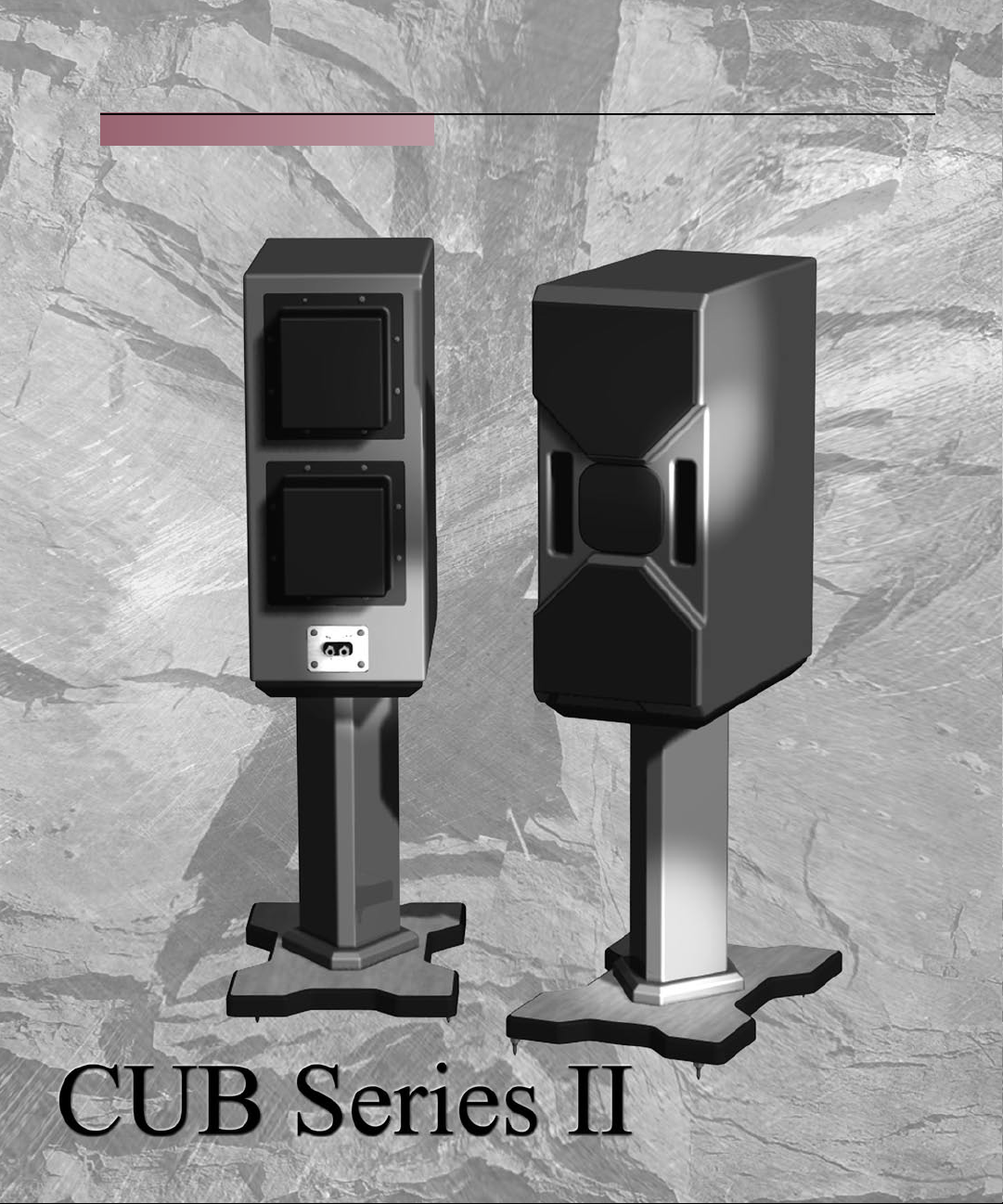
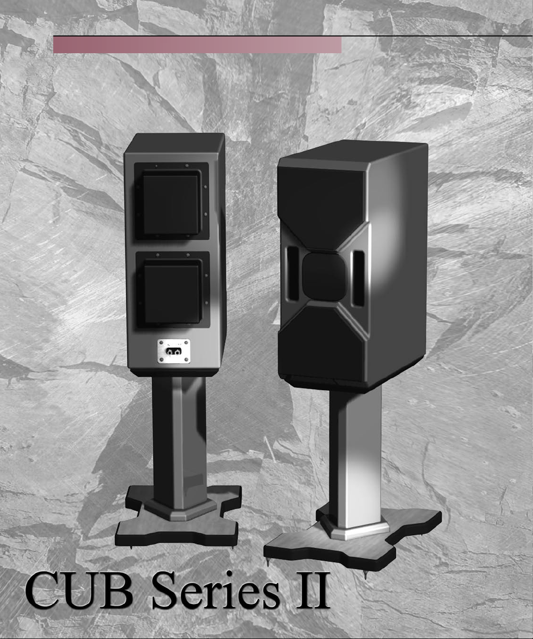
CUB SERIES II:
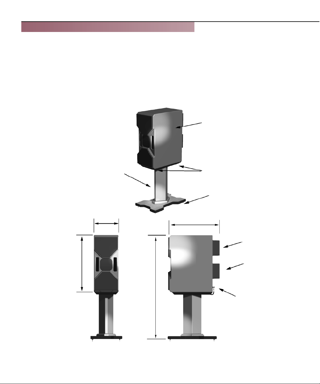
CO M PO N E N T S A N D DIM E N S I O N S
CUB ENCLOSURE
22 IN.
NON-RESONANT
STAND
9.5 IN.
CUB BOLTS
TO STAND
SPIKES
19.5 IN.
HIGH
FREQUENCY
CROSSOVER
LOW
FREQUENCY
CROSSOVER
40 IN.
BINDING
POSTS
iii
Page 7

C U B S P E C I F I C A T I O N S
CUB SERIES II:
SPECIFICATIONS
Nominal Impedance 4 ohms
Minimum Amplifier Power 10 Watts per channel
Woofer 2 - 6.5 inch double front ported
Overall Dimensions
Height - 22 inches
Width - 9.5 inches
Depth - 19.5 inches
Tweeter 1 - 1 inch inverted Titanium Dome
Weight (approx.): 75 lbs
Frequency Response
(with port contribution) 39 Hz - 22 kHz
Sensitivity 94 dB (2.83 volts at 1 meter)
iv
Page 8

Page 9
C U B I N T R O D U C T I O N
1
Page 10

Page 11

C U B I N T R O D U C T I O N
APPLICATIONS
Your CUB precision loudspeaker has been carefully designed to provide superb,
uncolored, limited full frequency range response in a single enclosure. Due to our very
successful research on the WATT/PUPPY and X-1 Grand SLAMM systems, the CUB has a
sonic character quite similar to its larger predecessors.
Using structural enclosure, speaker driver, and time alignment technologies developed for the WATT/PUPPY and the X-1 Grand SLAMM the CUB is truly the thoroughbred
of its class, and is well suited to carrying on the heritage of Wilson Audio speakers.
One of David Wilson’s most important criteria in speaker development is that a
speaker meets the accuracy and dynamic demands of studio monitoring, analytical hardware
and software evaluation and critical music listening. Therefore, the CUB has been designed
to deliver all of the speed, dynamics and musical accuracy to satisfy even the most demanding music lovers.
The CUB has also been engineered to take full advantage of today’s multichannel
surround formats, especially the latest AC-3 (Dolby Digital) and DTS (Digital Theater
Systems) formats. The CUB will provide the speed, dynamic impact and realism you have
come to expect in a high performance home theater systems.
1-1
Page 12

C U B O W N E R ʼ S M A N U A L
DESIGN CONSIDERATIONS
Your CUB has been designed to perform all of the specific functions of a high performance studio monitor in a less costly, scaled version of the WATT/PUPPY. This was
a difficult task, because a small enclosure is needed for high speed and linearity in lowermid to high frequency playback, yet the CUB needed to convincingly suggest the size and
weight of full scale, full range music. To accomplish this task David Wilson and his engineering department used some extraordinary materials and enclosure techniques. The discussion of a few of these materials follows.
ENCLOSURE MATERIALS TECHNOLOGY
The enclosure of the CUB uses the same proprietary techniques as have been very
successfully used in the X-1 Grand SLAMM, MAXX and the WATT/PUPPY systems. The
enclosure is made from a non-resonant material that is highly-cross braced to further reduce
cabinet resonance. The front baffle of the CUB, its most critical surface, is machined from
our proprietary Phenolic based structural material developed for the X-1 Grand SLAMM.
ADHESIVE
What’s in an adhesive? Everything. This often over looked element is crucial to the
proper performance of a loudspeaker. Correct modulus of elasticity, coefficient of thermal
expansion and natural frequency response are just a few of the important elements.
A highly cross-linked, thermoset adhesive is used for the construction of the enclosure. It was also chosen for its excellent bond strength, solvent resistance, hardness and
optimum vibrational characteristics.
1-2
Page 13

C U B I N T R O D U C T I O N
DEPTH OF DESIGN
The combination of the best in composite materials and adhesive technology, provided to us by the leaders in their industry, allow us to design an enclosure with unmatched
performance. The Cub has been designed to eliminate vibration and cabinet signature, while
maintaining an internal acoustical integrity that is simply, the best.
Further, the Cub loudspeaker has over 340 constraining relationships defining the
placement of over 75 parts. These relationships ensure both dimensional stability and repeatability. In short, the first Cub built will be as good as the thousandth.
CONCLUSION
All of these structural aspects combine to allow Wilson Audio to deliver a product
that maintains the strictest structural tolerances, durability and reliability. This also means
that you will have consistent, repeatable performance, unaffected by the climatic conditions,
anywhere in the world.
1-3
Page 14

Page 15
C A R E O F T H E C U B L O U D S P E A K E R
2
Page 16

Page 17

C A R E O F T H E C U B L O U D S P E A K E R
CARE OF THE FINISH OF YOUR CUBS
Your Cub loudspeaker enclosures are hand-painted with Wilsongloss™ paint and
hand-polished to a high luster. While the paint seems quite dry to the touch, final curing
and complete hardening takes place over a period of several weeks. To protect the finish of
the Cubs during final manufacturing, shipment, and setup in your listening room, we have
applied a removable layer of protective film over the finish. We recommend that this film
be left in place until the speakers are in their final location in your listening room. Once
you have determined their final position, remove the film by peeling it off. Do not leave
this film on indefinitely, as it will leave impressions on the paint. It is important that the
delicate paint finish of the Cub be dusted carefully with the dust cloth, which has been provided. We recommend that the following procedure be observed when dusting the speakers:
• Blow off all loose dust
• Using the dust cloth as a brush, gently whisk
off any remaining loose dust
• Shake out the dust cloth
• Dust the finish, using linear motions in one direction parallel to
the floor. Avoid using circular or vertical motions.
Because the paint requires a period of several weeks to fully cure, we recommend
that no cleaning fluids such as glass cleaners be used during this initial period of time.
When the paint is fully cured, heavy finger prints and other minor smudges may be removed
with a glass cleaner. Always use the dust cloth. Stronger solvents are not recommended
under any circumstances. Consult your dealer for further information if required. Periodic
polishing may be desired over the years to maintain the high luster of the finish. We recommend a nonabrasive carnauba-based wax and soft cloth.
2-1
Page 18

C U B O W N E R ʼ S M A N U A L
BREAK IN PERIOD
All audio equipment will sound its best after the components have been broken in for
some period of use. Wilson Audio breaks in all woofers and mid-range drivers for a 12 hour
period. All drivers are then tested, calibrated, and matched for their acoustical properties. In
your listening room, expect 25-50% of break-in to be complete after two hours of playing
music fairly loudly. Ninety percent of break-in is complete after 24 hours of playing. Playing a “disc repeat” overnight can accomplish this task quickly. Wilson Audio recommends
chamber music for this task.
BINDING POSTS
The binding posts used with the Cub are specifically made for Wilson Audio.
David Wilson and his engineering team spent many hours listening to a variety of
binding posts and making modifications to each until the most musical combination
was achieved.
Note:The binding posts should be tighted only snuggly. Over tightening can result in
the breakage of the posts. Please take care when attaching the spade lugs to the Cub.
2-2
Page 19

C A R E O F T H E C U B L O U D S P E A K E R
T E C H N I C A L - N O T E
If the user wishes to test the polarity of the Cub with a battery, the plus (+) terminal of the battery is connected to the RED (+) input terminal of the Cub and
the negative (-) terminal of the battery is connected to the BLACK (-) terminal
of the Cub. The results of this test will show the Cub woofers to move outward.
This is the correct driver movement in response to a D.C. signal.
2-3
Page 20

Page 21

I N Y O U R R O O M
3
Page 22

Page 23

I N Y O U R R O O M
ROOM REFLECTIONS
There are 3 commonly encountered room reflection problems, slap-echo, standing
waves, and comb filter effects.
SLAP-ECHO
Probably the most obnoxious form of reflection is the slap echo. In slap echo, primarily mid-range and high frequency sounds reflect off of two parallel hard surfaces. The
sound literally reverberates back and forth until it is finally dissipated over time. You can
test for slap echo in any room by clapping your hands sharply in the middle of the room and
listening for the characteristic sound of the echo in the mid-range. Slap echo destroys the
sound quality of a stereo system primarily in two ways:
• Adding harshness to the upper mid-range and treble through
energy time storage.
• Destroying the delicate phase relationships which help to establish
soundstage and image localization clues.
3-1
Page 24

C U B O W N E R ʼ S M A N U A L
Nonparallel walls do not support slap echo, but rather allow the sound to diffuse.
Slap echo is a common acoustical problem in the typical domestic listening room, because most of these rooms have walls of a hard, reflective nature, usually being only occasionally interrupted by curtains or drapes. Slap echo can be controlled entirely by the
application of absorptive materials to hard surfaces, such as:
• Sonex
• Airduct board
• Cork panels
• Large ceiling to floor drapes
• Carpeting to wall surfaces
In many domestic listening environments, heavy stuffed furnishings are the primary
structural control to slap echo. Unfortunately, their effectiveness is not predictable. Diffusers are sometimes also used to very good subjective effect, particularly in quite large
rooms. Sound absorbent materials such as described above will alter the tonal characteristic of the room by making it sound “deader, much heavier in bass tonal balance, less
“bright and alive” and “quieter.” These changes usually make the room more pleasant
for conversation, but sometimes render it too dull in the high frequencies to be musically involving. Diffusers, on the other hand, tend to not change the high frequency tonal
balance characteristic of the room, but make the sound more “open”. A combination of
absorbtive and diffusive treatments is usually the best approach.
STANDING WAVES
Another type of reflection phenomenon is standing waves. Standing waves cause
the unnatural boosting of certain frequencies, typically in the bass, at certain discreet locations in the room. A room generating severe standing waves will tend to make a loudspeaker sound one way when placed in one location and entirely different when placed
in another. The effects of standing waves on a loudspeaker’s performance are primarily,
as follows:
• Tonal balance-Bass too heavy
• Low-level detail- Masked by long reveration time LF standing
waves
3-2
Page 25

I N Y O U R R O O M
• Sound staging- LF component of image shifted
Standing waves are more difficult to correct than slap echo because they tend
to occur at lower frequencies, whose wave lengths are long enough to be ineffectively
controlled by absorbent materials such as Sonex. Moving speakers about slightly in the
room is, for most people, their only control over standing waves. Sometimes a change
of placement of as little as one inch can dramatically alter the tonal balance of a system
because of standing wave problems. Fortunately, minor low frequency standing waves
are sometimes well controlled by positioning tube traps in the corners of the room. Very
serious low frequency accentuation usually requires a custom-designed bass trap system.
Low frequency standing waves can be particularly troublesome in rooms constructed of concrete or brick. These materials trap the bass in the room, unless it is allowed to leak out of the room, through large window and door areas.
In general, placement of the speaker in a corner will excite the maximal number
of standing waves in a room, and is to be avoided for most direct radiator, full range
loudspeaker systems. Some benefit is achieved by placing the stereo pair of loudspeakers slightly asymmetrically in the listening room so that the standing waves caused by
the distance between one speaker and its adjacent walls and floors are not the same as
the standing wave frequencies excited by the dimensions in the other channel.
Comb Filter Effect
A special type of standing wave, noticeable primarily in the mid-range and lower
higher frequencies is the so-called “comb filter effect”.
Acoustical comb filtering occurs when sound from a single source, such as a
loudspeaker, is directed toward a microphone or listener at a distance. The first sound to
reach the microphone will be the direct sound, followed by delayed reflected sound. At
certain frequencies cancellation occurs, because the reflected sound lags in phase relative to the direct sound. This cancellation is most apparent where the two are 180 degrees out of phase. There is augmentation at other frequencies where the direct and the
reflected sounds arrive in phase. Because it is a function of wave length, the comb filter
effect will notch out portions of the audio spectrum at regular octave-spaced intervals.
3-3
Page 26

C U B O W N E R ʼ S M A N U A L
The subjective effect of comb filter effects, (such as is shown in Figure 1) is as follows:
• Added roughness to the sound
• Reduction of harmonic richness
• Smearing of lateral sound stage image focus and placement
Comb filter effects are usually caused by side wall reflections. They are best controlled by
very careful speaker placement and by the placement of Sonex or air duct panels applied to
that part of the wall where the reflection occurs.
REFLECTIVE ACOUSTICAL COMB FILTER EFFECT
3-4
FIGURE 1
Page 27

I N Y O U R R O O M
RESONANCES
Resonance in listening rooms are generally caused by two sources:
• The structures within the listening room
• The volume of the air itself in the listening room
STRUCTURAL RESONANCES
Structural resonances are familiar to most people as buzzes and rattles, but this type
of resonance usually only occurs at extremely high volume levels, and is usually masked
by the music. In many wood frame rooms, the most common type of structural resonance
problem is “booming” of walls and floors. You can test for these very easily by tapping
the wall with the heel of your hand or stomping on the floor. If it is a wooden floor, this is
done to detect the primary spectral center of the resonance. To give you an idea of what the
perfect wall would sound like, imagine rapping your hand against the side of a mountain.
Structural wall resonances generally occur in the low to mid-bass frequencies and add tonal
balance fullness to any system played in that room. They too are more prominent at louder
levels, but their contribution to the sound of the speaker is more progressive. Rattling
windows, picture frames, lamp shades, etc. can generally be silenced with small pieces of
caulk or with blocks of felt. Short of actually adding additional layers of sheet rock or book
shelves, to flimsy walls, however, there is little that can be done to eliminate wall resonances.
AIR VOLUME RESONANCE
The volume of air in a room will also resonate at a frequency determined by the size
of the room. Larger rooms will resonate at a lower frequency than will smaller rooms. Air
volume resonances, wall panel resonances, and low frequency standing waves, together,
combine to form a low frequency coloration in the sound. At its worst, it is a grossly exaggerated fullness, which tends to obscure detail and distort the natural tonal balance of the
speaker system. Occasionally, however, there is just enough resonance to give a little added
warmth to the sound... an addition some listeners prefer. Tube traps manufactured by the
ASC corporation have been found to be effective in reducing some of these low frequency
room colorations. While custom designed and constructed bass traps, such as perforated
Helmholtz resonators, provide the greatest degree of low frequency control.
Page 28

C U B O W N E R ʼ S M A N U A L
ROOM SHAPES
There are three basic shapes for most rooms: square, rectangular, and L-shaped (see
Figure 2). A perfectly square room is the most difficult room in which to set up speakers be-
cause, by virtue of its shape, square rooms are the perfect medium for building and sustaining
standing waves. Standing waves are pressure waves created by the integration of sound and
opposing, parallel walls which accentuate particular frequencies. They heavily influence the
music played by loudspeakers, greatly diminishing the quality of the listening experience.
Long, narrow rectangular rooms also pose their own special acoustical problems for
speaker setup. They have the ability to set up several standing wave nodes, which will have
different frequency exaggerations depending on where you are sitting. Additionally, these
long rooms are often quite lean in the bass near the center of the room. Rectangular rooms
are still preferred to square rooms because by having two sets of dissimilar length walls,
standing waves are not as strongly reinforced and will dissipate more quickly than in a square
room. In these rooms the preferred speaker position for spatial placement and midrange reso-
lution would be on the longer walls. Bass response would be reinforced, albeit not predict-
ably, by speaker placement on the short walls.
In many cases L-shaped rooms offer the best environment for speaker setup. Ideally
speakers should be set up along the primary (longest) leg of the room. They should fire from
the end of the leg (short wall) toward the bend, or they should be along the longest wall, with
the speaker furthest to the bend being inside of the bend. In this way both speakers are firing
the same distance to the back wall. The asymmetry of the walls in L-shaped rooms resists
the buildup of standing waves.
3-6
Page 29

I N Y O U R R O O M
COMMON ROOM SHAPES:
OPTIMUM SPEAKER PLACEMENTS
FIGURE 2
3-7
Page 30

C U B O W N E R ʼ S M A N U A L
SPEAKER PLACEMENT VS. LISTENING POSITION
The location of your listening position is as important as the careful setup placement
of your Cub speakers in your room. The listening position should ideally be no more than
1.1 to 1.25 times the distance between the tweeters on each speaker. Therefore, in a long
rectangular room of 12’ x 18’, if the speaker tweeters are going to be 9’ apart, you should be
sitting 9’11’’ to 11’3’’ from the speaker. This would be about halfway down the long axis of
the room. Experiment carefully for best low frequency response.
Some people place the speakers on one end and sit at the other end of the room.
Needless to say, this will not yield the finest sound. Carefully consider your listening position
for optimal performance. Our experience has shown that any listening position which places
your head closer than 14” to a room boundary will diminish the sonic results of your listen-
ing.
CHOOSING A LISTENING POSITION
Decide where you want your listening position to be. Please remember that your
Cub can fill most rooms with beautiful sound. However, for the time aligning advantage, we
want to ensure that you get all the benefits possible with the group delay adjustment features
that are built into this design. For this purpose we ask you to consider the following ques-
tions:
What is the main purpose of your Cubs? Is it for a listening room dedicated to 2-
channel audio? If yes, you should choose your position carefully to yield the finest sound.
Are your Cubs dedicated for a home theater?
Are you going to sit on a couch, or will there be multiple rows of chairs?
If it is a couch, you should center the loudspeakers on the center position of the
couch.
Multiple rows of chairs - In this case you should calculate the 1.2 times equation on
your second row of seating. Now more people will enjoy the power of your Cubs.
Do you still want to listen to 2 channel music at its highest quality? In this way you
can enjoy optimized sound from that second seat.
3-8
Page 31

I N Y O U R R O O M
SPEAKER ORIENTATION
Speaker placement and orientation are two of the most important considerations in
obtaining superior sound. The first thing you need to do is minimize the influence of the side
walls on the sound of your system. Speakers placed too close to the side walls will suffer
from a strong primary reflection. This can cause out-of-phase cancellations, or comb filter-
ing, which will cancel some frequencies and change the tonal balance of the music. A good
place to start is with the speakers about 18” from each wall and, if you need to move them
relative to the side wall, move them away from the wall, not closer.
A very important aspect of speaker placement is how far to place the speakers from
the wall behind them. The closer to the back wall the more pronounced the low bass energy
and centering of the image will be. However, this comes at a definite reduction in stage size
and bloom, as well as a deterioration of upper bass quality. You must find the proper balance
of these two factors, but remember, if you are partial to bass response or air and bloom, do
not overcompensate your adjustments to maximize their effects. Overbalanced systems are
sometimes pleasing in the short term, but long term satisfaction is always achieved through
proper balance.
FIGURE 3- CUBS TOED IN
3-9
Page 32

C U B O W N E R ʼ S M A N U A L
The Cub is designed for maximum phase coherence and pulse replication accu-
racy when they are aimed directly at the listener or microphone. Thus, your Cubs should
be “toed in.” (see Figure 3) In other words, the listener, when seated in the listening
position, should just barely see the surface of the inner side of the Cub. Toeing in the
speakers provides dramatic improvements in resolution of low level detail in the mid-
range, as well as dramatic improvements in sound staging performance.
SUMMARY
Ideally, the speakers should not be positioned too far from the listener, if maximum resolution of low level detail is required (near-field monitoring). If possible, the
speakers should be positioned out into the room, slightly asymmetrically away from side
and rear walls. The speakers should be toed-in toward the listener, preferably so that
the listener at his seated position can barely see the surface of the inner side panel of the
Cub as he faces the speaker. It is recommended that a distance of 2-3 feet, and possibly
more, be maintained between the Cub and the rear walls and a distance of at least 1 1/2
feet be maintained between the front panel of the Cub and reflective side walls. Use of
sound absorbent materials may reduce the space requirement somewhat. Experiment for
each room.
By following the guidelines in this manual and your own common judgement,
your new Cub speakers will provide you with a lifetime of pure music reproduction.
3-10
Page 33

I N Y O U R R O O M
3-11
Page 34

Page 35

C U B S Y S T E M I I S E T U P
4
Page 36

Page 37

C U B S Y S T E M I I S E T U P
Note: Before setting up the Cub System II study carefully the previous section on room
acoustics. It provides valuable information on determing the ideal room location for your
speakers.
PREPARATION
You will need the following items:
• Supplied hardware kit
• Tape measure
• Known listening position
SETUP PROCEDURE
1. Stand the unit up (inside the crate) and gently walk/slide the CUB out of the
crate. Remove the plastic outer bag by tilting the CUB over and opening the
bag at the base of the CUB. Stand the CUB up and remove the bag.
Note: Do not cut the bag off of the CUBs. You may mark the cabinet or damage a
driving element. Additionally, you will need this bag, if you need to repackage the
CUBs. Save your shipping crates and all packing materials, they are specifically designed to prevent harm from coming to your CUBs.
2. Move the CUBs into the desired location.
Note: Be careful not to touch the driving elements when you are moving your
CUBs!
4-1
Page 38

C U B O W N E R ʼ S M A N U A L
Note: If you did not purchase the optional stand skip to step 5.
3. Set the stands in the desired listening location and attach the spikes.
(see Figure 4 below)
Cub Stand Spike
FIGURE 4- INSTALLING THE CUB STAND SPIKES
P R O T E C T Y O U R F I N I S H
Note: Your CUB loudspeaker enclosures are hand-painted with Wilsongloss paint and
hand-polished to a high luster. While the paint seems quite dry to the touch, final curing
and complete hardening takes place over a period of four weeks. To protect the finish of the
CUBs during final manufacturing, shipment, and setup in your listening room, we have installed a removable layer of protective film,over the finish. We recommend that this film be
left in place until the speakers are in their final location in your listening room. Once you
have determined their final position, remove the film by gently peeling it off. Do not leave
this film on indefinitely, as it may leave impressions on the paint.
4-2
Page 39

C U B S Y S T E M I I S E T U P
4. Bolt the Cub to the stand using the four 1/4-20 threaded bolts provided.
(see Figure 5)
Note: Do not over tighten the bolts, a snug fit is all that is required to secure the
Cub to the stand.
Anchor Bolt
Anchor
Bolt
FIGURE 5- BOLTING THE CUB TO THE
STAND
4-3
Page 40

C U B O W N E R ʼ S M A N U A L
SPEAKER CABLES
The very high current input terminals located on the rear of your Cub loudspeaker
are color coded with a small plastic plug, so that RED corresponds to positive and black to
negative, common, or ground on the amplifier output. Be sure to connect the loudspeakers
in phase with each other. We recommend the use of the very highest quality loudspeaker
cables, particularly those designed for high frequency propagation correction and phase
linearity. Beware of “zip cord” type speaker cables which will smear the sound from your
Cubs, and limit their effective bandwidth. Also, do not use braided litz type loudspeaker
cables as they will cause an unnatural brightness to the sound, compromise sound staging
performance, and may cause instability, oscillation and damage in wide bandwidth solid
state amplifiers.
SPADE LUGS
The spade lugs of some of the high quality cables often used with the Cub are angled
to reduce pressures on the cable during installation. Avoid the instinct to push the cable’s
spade lug ends all the way into the Cub’s connectors (see Figure 6 ). Partial insertion of
these angled spade lugs will actually improve the reliability of the connection. Flat lugs may
be fully inserted to connectors before tightening.
4-4
Page 41

C U B S Y S T E M I I S E T U P
FIGURE 6- SPADE LUG ATTACHMENT
4-5
Page 42

C U B O W N E R ʼ S M A N U A L
Connection of the Cub to the Power Amplifier
1. Turn off the power amplifier(s) and remove the AC power cord from the wall
outlet.
2. Lay out the speaker cables before hooking them up to the CUBs. Make sure that
there are no kinks, twists, or right-angle bends in the cable. If you need to turn corners, attempt to use a gradual curve as opposed to a severe right-angle bend.
3. Connect the negative (normally Black) end of the speaker cable to the high current speaker binding post with the engraved “-” above it ( see Figure 7).
4-6
Note: Do not over tighten the binding posts, overtightening can cause the posts to
break off.
4. Connect the positive (normally Red) end of the speaker cable to the high current
speaker binding post with the engraved “+” above it.
5. Plug your amplifier(s) AC power cord into the wall outlet.
Note: Always attempt to keep your pair of speaker cables the same length. This will
ensure that the signals arrive at each speaker in the proper time frame, by traveling
the same distance to each speaker.
Page 43

C U B S Y S T E M I I S E T U P
Proper attachment
FIGURE 7- CUB CABLE CONNNECTION
4-7
Page 44

C U B O W N E R ʼ S M A N U A L
COMPLETED SETUP
The setup of the Cub series
II loudspeaker is now completed.
If you are in need of further assistance contact your local dealer and
they can answer any further setup
questions that you may have.
4-8
FIGURE 8- COMPLETED SETUP
Page 45

C U B S Y S T E M I I S E T U P
Page 46

Page 47

WARRANTY INFORMATION
5
Page 48

Page 49

W A R R A N T Y I N F O R M A T I O N
Wilson Audio
Warranty Information
LIMITED WARRANTY
Subject to the conditions set forth herein, Wilson Audio warrants its loudspeakers
to be free of manufacturing defects in material and workmanship for the Warranty
Period. The Warranty Period is a period of 90 days from the date of purchase by
the original purchaser, or if both of the following two requirements are met, the Warranty Period is a period of five (5) years from the date of purchase by the original
purchaser:
Requirement No. 1. No later than 30 days after product delivery to the
customer, the Warranty Registration Form must have been returned by
the customer to Wilson Audio;
Requirement No. 2. The product must have been professionally installed by
the Wilson Audio dealer that sold the product to the customer.
FAILURE TO COMPLY WITH EITHER REQUIREMENT NO. 1 OR REQUIREMENT
NO. 2 WILL RESULT IN THE WARRANTY PERIOD BEING LIMITED TO A PERIOD
OF 90 DAYS ONLY.
CONDITIONS
This Limited Warranty is also subject to the following conditions and limitations.
The Limited Warranty is void and inapplicable if the product has been used or handled other than in accordance with the instructions in the ownerʼs manual, or has
been abused or misused, damaged by accident or neglect or in being transported,
or if the product has been tampered with or service or repair of the the product has
been attempted or performed by anyone other than Wilson Audio, an authorized
5-1
Page 50

C U B O W N E R ʼ S M A N U A L
Wilson Audio Dealer Technician or a service or repair center authorized by Wilson
Audio to service or repair the product. Contact Wilson Audio at (801) 377-2233
for the location of Wilson Audio Dealers and authorized service and repair centers.
Most repairs can be made in the field. In instances where return to Wilson Audioʼs
factory is required, the dealer or customer must first obtain a return authorization.
Purchaser must pay for shipping to Wilson Audio, and Wilson Audio will pay for
shipping of its choice to return the product to purchaser. A RETURNED PRODUCT
MUST BE ACCOMPANIED BY A WRITTEN DESCRIPTION OF THE DEFECT.
Wilson Audio reserves the right to modify the design of any product without obligation to purchasers of previously manufactured products and to change the prices or
specifications of any product without notice or obligation to any person.
REMEDY
In the event that the product fails to meet the above Limited Warranty and the
conditions set forth herein have been met, the purchaserʼs sole remedy under this
Limited Warranty shall be to: (1) contact an authorized Wilson Audio Dealer within
the Warranty Period for service or repair of the product without charge for parts or
labor, which service or repair, at the Dealerʼs option, shall take place either at the
location where the product is installed or at the Dealerʼs place of business; or (2) if
purchaser has timely sought service or repair and the product cannot be serviced
or repaired by the Dealer, then purchaser may obtain a return authorization from
Wilson Audio and at purchaserʼs expense return the product to Wilson Audio where
the defect will be rectified without charge for parts or labor.
WARRANTY LIMITED TO ORIGINAL PURCHASER
This Limited Warranty is for the sole benefit of the original purchaser of the covered
product and shall not be transferred to a subsequent purchaser of the product, unless the product is purchased by the subsequent purchaser from an authorized
Wilson Audio Dealer who has certified the product in accordance with Wilson Audio
standards and requirements and the certification has been accepted by Wilson Audio, in which event the Limited Warranty for the product so purchased and certified
shall expire at the end of the original Warranty Period applicable to the product.
5-2
Page 51

DEMONSTRATION EQUIPMENT
Equipment, while used by an authorized dealer for demonstration purposes, is warranted to be free of manufacturing defects in materials and workmanship for a period of five (5) years from the date of shipment to the dealer. Demo equipment needing warranty service may be repaired on-site or, if necessary, correctly packed and
returned to Wilson Audio by the dealer at the dealerʼs sole expense. Wilson Audio
will pay return freight of its choice. A returned product must be accompanied by a
written description of the defect. Dealer owned demonstration equipment sold at
retail within two (2) years of date of shipment to the dealer is warranted to the first
retail customer to be free of manufacturing defects in materials and workmanship
for the same time periods as if the product had originally been bought for immedi-
ate resale to the retail customer. Wilson Audio products are warranted for a period
of 90 days, unless extended to 5 years, as provided above, by return and filing of
completed Warranty Registration at Wilson Audio within 30 days after product delivery to customer and the product was professionally installed by the Wilson Audio
Dealer that sold the product to the customer.
MISCELLANEOUS
ALL EXPRESS AND IMPLIED WARRANTIES NOT PROVIDED FOR HEREIN ARE
HEREBY EXPRESSLY DISCLAIMED. ANY LEGALLY IMPOSED IMPLIED WARRANTIES RELATING TO THE PRODUCT SHALL BE LIMITED TO THE DURATION OF THIS LIMITED WARRANTY. THIS LIMITED WARRANTY DOES NOT
EXTEND TO ANY INCIDENTAL OR CONSEQUENTIAL COSTS OR DAMAGES TO
THE PURCHASER. Some states do not allow limitations on how long an implied
warranty lasts or an exclusion or limitation of incidental or consequential damages,
so the above limitations or exclusions may not apply to you. This Limited Warranty
gives you specific legal rights, and you may also have other rights, which vary, from
state to state.
Page 52

Page 53

T R O U B L E S H O O T I N G G U I D E
A
Page 54

Page 55

T R O U B L E S H O O T I N G G U I D E
SECTION 6.0 TROUBLESHOOTING SETUP DIFFICULTIES
Problem Reason
One channel is not operating... Check inter-connects from source.
Check the connections on the speaker cables.
Both at amplifier and speaker ends. Watch especially for connector touching each other.
Imaging is off center... Check your connections. When a tweeter or mid-
range driver is not working, or is out of phase, the
imaging will be off. Double check your connections for red-to-red and black-to-black.
Play music at a low level, and listen to each driver
in each channel. You may have a driver that is
not operating correctly. If you find a driver that is
silent please go to the “Driver Out section” of this
troubleshooting guide.
A chronic lack of bass energy...Check the input cable connections on your woofer
enclosure. If one channel is out of phase (connections reversed), bass will be cancelled.
Driver not playing after
Note: Turn off your amplifier, and unplug it from
connections have been
verified.
the wall.
If you have found a driver that would not play,
move to the rear of this particular loudspeaker.
A-1
Page 56

C U B O W N E R ʼ S M A N U A L
Using the 1/8” Allen wrench remove the crossover
for the driver that is out (upper crossover is for
tweeter, lower crossover is for the midrange)
Locate the resistor and remove the resistor using
a soldering iron. Replace the resistor and solder
the new resistor in the old ones place.
Note: An improper resistor value will deteriorate
your speaker performance
Plug your amplifier into the wall and turn it on.
Listen to the channel at a low level. The driver
should now be operating correctly.
Amplifier shuts off as soon
as it is turned on: Check to see if your speaker cables are properly
secured. Look for frayed ends, loose connections,
a conductor contacting the amplifier chassis.
A-2
Turn the amplifier off and disconnect it from the
AC wall outlet. Disconnect the preamplifier leads
to the amplifier. Now turn back on the amplifier.
If the problem is solved:
wrong with your preamplifier or interconnect. Call
your dealer.
If the problem persists:
disconnected and continue on to the next step.
Turn the amplifier off and disconnect it from the
AC wall outlet. Disconnect the speaker leads at
the main input to the speaker . Now turn the
amplifier on.
There is something
Leave the pre-amp leads
Page 57

T R O U B L E S H O O T I N G G U I D E
If the problem is solved:
dealer. There may be a problem with the crossover or the speakerʼs internal wiring.
If the problem persists
step.
Turn the amplifier off and disconnect it from the
AC wall outlet. Disconnect the speaker cable
leads to the amplifier and turn the amplifier on
again.
If the problem is solved:
your speaker cables. Check for frayed ends,
holes (from spike feet), or make sure that your
spade lug is not touching the chassis while it is
connected to the binding post.
If the problem persists:
you bought your amplifier. You appear to have a
problem with this component.
Call your Wilson Audio
continue on to the next
You have a short in
Call the dealer where
A-3
Page 58

Page 59

R E P A I R P R O C E D U R E S
B
Page 60

Page 61

R E P A I R P R O C E D U R E S
REPLACING A BLOWN RESISTOR
The cub loudspeaker had protective resistors that will blow if the speaker is over-
driven, or if a power surge moved through the system. This is done so that the driver is not
damaged. Replace a resistor on the cub as follows:
1. Determine which driver is not playing music.
2. Remove the appropriate crossover can from the back of the cub enclosure by
removing each of the 10-32 button head machine screws from the crossover
see figure below.
Note: Support the crossover as you remove the screws so that is does not fall and damage the
internal wiring.
HIGH
FREQUENCY
CROSSOVER
10-32
MAHCINE
SCREW
LOW
FREQUENCY
CROSSOVER
B-1
Page 62

C U B O W N E R ʼ S M A N U A L
3. Heat up the leads of the resistor with a 45 watt soldering pencil and remove
the faulty resistor (see figure below).
4. Wrap the leads of the new resistor around the ends of the posts and re-solder
the leads.
Note: The tweeter resistor value is 4.2 ohms
The low frequency resistor value is 1 ohm
5. Re-attach the crossover can to the enclosure, making sure not to over tighten
the screws.
B-2
Resistor
Soldered
Posts
Page 63

R E P A I R P R O C E D U R E S
REPLACING A BAD DRIVER
If you believe that a driver is blown make sure that you have tried replacing the pro-
tective resistor before you replace the driver. No sound coming from a driver is often a blown
resistor and not a bad driver. If you need to replace a driver do so as follow:
1 Using the supplied Allen wrench, remove the machine screws
holding the driver in place.
2 Insert the Allen wrench into one of the driver screw holes 1/8”.
Gently lift out the driver and place it onto the foam pad covering
the front baffle.
Note: it is best to place an old towel under the driver so that you will not damage the
enclosure when unsoldering the driver.
3 Using a 900 degree F soldering iron heat, up the solder joints and remove the
driver.
4 Melt a small 1/8” diameter bead of solder onto the tip of each wire, heat the
wire up until you see the solder wick into the copper.
5 Place the replacement driver onto the cloth and solder on the wires to the
driver. White wire to the positive side and black to the negative. The positive
side is generally indicated by a red dot. Make sure to heat up the solder joint
completely and hold firmly in place until the solder sets.
6 Replace the driver foam gasket.
7 Place the driver into the machined recess.
8 Replace the machine screws, tightening them to 20 inch/ pounds of
torque.
Note: Be careful not to over tighten the screws, it may cause the brass insert to spin.
B-3
Page 64

 Loading...