

Wilson 3A-750, 3A-1000, 3A-450 User Manual
SPECIFICATIONS
SM-97
SM-97
Model no. 3A-450
38640-0450
Free Speed (RPM)
Min. Torque Ft-Lb
Max. Torque Ft-Lb
Air Pressure psi
Air Inlet
Hose
Air Flow @Free
Speed
Spindle
450 750 1000
3 3 3
18 12 10
3A-750
38640-0750
90
3/8” NPT
3/8” I.D.
32 CFM
1/2” Dia. with 2 spots
3A-1000
38640-1000
Torq-Air-Matic
ڤModel 3A-450 (450RPM)
ڤModel 3A-750 (750RPM)
ڤModel 3A-1000 (1000RPM)
Thomas C. Wilson, Inc.
21-11 44th Avenue, Long Island City, New York 11101
Tel: (718)729-3360 Fax: (718)361-2872 http://www.tcwilson.com
16
Email: tcwilson@tcwilson.com
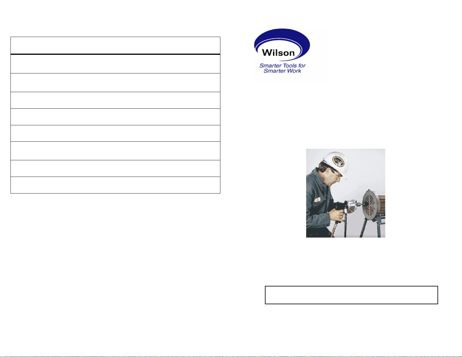
OPERATING INSTRUCTIONS &
SERVICE MANUAL
TO REDUCE THE RISK OF INJURY, USER MUST READ AND
UNDERSTAND OPERATOR’S MANUAL.
Thomas C. Wilson, Inc.
21-11 44th Avenue, Long Island City, New York 11101
Tel: (718)729-3360 Fax: (718)361-2872 http://www.tcwilson.com
Email: tcwilson@tcwilson.com

SAFETY INSTRUCTIONS
SM-97
TROUBLE-SHOOTING (Cont’)
SM-97
READ AND UNDERSTAND ALL INSTRUCTIONS
Failure to follow all instructions listed below, may result
in accident, fire and/or personal injury.
!
SAVE THESE INSTRUCTIONS
WA R NI N G!
1. Do not allow corrosive gases or foreign material to enter
the unit. Moisture, oil-based contaminants, or other liquids
must be filtered out.
2. Eye protection is always required when running motor.
3. Hearing protection is recommended when in close proximity to all operating air motors.
4. Dust mask, non-skid safety shoes, hard hat, gloves and
other personal safety equipment must be used.
5. Stay alert, watch what you are doing, and use common
sense when operating a power tool.
6. Dress properly. Do not wear loose clothing or jewelry.
7. Keep your work area clean and well lit.
8. Do not operate power tools in explosive atmospheres, such
as in the presence of flammable liquids, gases, or dust.
9. Disconnect the tool from the air supply before installing,
making any adjustment, changing accessories, servicing or
storing tool.
2
PROBLEM CAUSE & SOLUTION
Torque control will
not release at torque
setting
Torque control will
not relatch in reverse
Caution: Disassembly or reassembly of torque control unit must be
performed by qualified personnel. It is advisable to return torque
control units to the factory or consult the factory for necessary repair.
1. Broken latch release pawl
—Replace–see pg. 8, (Pc. #36, pg. 11).
2. Broken torque spring
—Replace–see pg. 8, (Pc. #5, pg. 11).
3. Broken latch
—Replace–see pg. 8, (Pc. #34, pg. 11).
4. Broken or excessive wear on tips of all pawls
—Replace-see pg8(Pc29,36,40&42, pg.11).
5. Broken spring ends or anchor pins of latch
pawls and reverse pawl
—Replace–see pg.8, (Springs & pins, pg. 11).
6. Reaction member seized to int. gear assembly
—Consult factory
7. Broken or short roll pin stop on reaction
member. Check for scoring on stop plate section of handle connector
—Replace–see pg. 7, (Pc. #32, pg. 11).
8. Ball retainer has broken or lost any balls.
Check correct assembly of retainers.
—Replace–see pg. 9, (Pc. #43, pg. 11).
1. Broken latch or latch spring
—Replace–see pg. 8, (Pc. #28,34, pg. 11).
2. Broken reverse pawls, springs or anchor pin
—Replace–see pg.8 (Pc#39,40,41,42, pg.11).
3. Slot radii on internal gear oversized/gouged
—Replace internal gear (Pc. #10, pg. 11)
4. Insufficient torque on drive spindle end
—See note on pg.5. Hold spindle end in vise
and manually turn TAM ccw; should relatch.
5. Excessive burrs or wear on internal gears preventing free rotation
—Debur/replace–see pg. 7,(Pc. #10, pg. 11).
15

TROUBLE-SHOOTING
SM-97
GUIDELINES FOR TUBE EXPANSION
SM-97
PROBLEM CAUSE & REMEDY
Motor will not run.
1. Inefficient air supply
—Check 90 psi and 32 CFM air supply.
2. Clogged air inlet screen
—Replace-see pg.6(pc #75, pg.13).
3. Broken or severely worn rotor blades
—Replace-see pg.6(pc #69, pg.13).
4. Rust due to improper storage of tool
—Disassemble and clean– Refer to Disassembly procedure.
5. Broken throttle valve pin or lever
—Replace–see pg.6(pc. #78/80, pg. 13).
Motor will not reach
RPM.
1. Insufficient air volume
—Check 32 CFM supply.
2. Dirty air inlet screen
—Clean –see pg. 6 (pc.#75, pg.13).
3. Worn rotor blades
—Replace-see pg.6(pc #69, pg.13).
4. Air supply hose chocked or too small
—See Operating Procedure recommended hose.
Motor stalls at high
torque
1. Insufficient air pressure
—Check 90 psi supply
2. Dirty air inlet screen
—Clean –see pg. 6 (pc.#75, pg.13).
3. Rotor blades worn, chipped or broken
—Replace-see pg.6(pc #69, pg.13).
Improperly rolled joints create additional expense to correct, whether
they are under-rolled and can be corrected merely by rerolling, or
over-rolled and require removal and replacement. The optimal joint is
one that develops a leak tight joint with adequate strength for the service intended with the minimum amount of cold working or reduction
of the tube wall. Experience
tainable with non-ferrous tubes in surface condensers by expanding
to a wall reduction of 3% to 4% after metal to metal contact of the
tube 0.D. with the tube sheet hole. Steel tubes in heat exchangers
may require wall
reductions of 5% to 10%; soft copper and aluminum tubes in heat exchangers also require larger wall reductions in the area of 8% to 12%.
Boiler tubes requiring development of optimum joint strength require
wall reductions of 12% to 14%.
A typical example of the application of this method is indicated for a
3/4” x 18 ga. tube in a condenser.
Tube Expansion Calculations
Tube Sheet Hole Dia. .760
- Tube O.D. -.750
= Clearance =.010
+ Tube I.D. +.652
=I.D. @ Metal to Metal =.662
+4%Reduction (.049x.04x2) +.004
=Expanded I.D. =.666
indicates that joints of this type are ob-
OPERATION
Motor fails to stop
14
1. Broken throttle valve spring
—Replace-see pg.6(pc #76, pg.13).
2. Valve ball does not seal
—Replace or rework valve seat-Refer to
pg. 6 (pc.#77, pg.13)
RECOMMENDED OPERATING AIR PRESSURE 90 PSI
1. Make sure there is an adequate supply of clean air of 90
psi lubricated with light machine oil of SAE 10 viscosity.
This should be done before all long runs of tube expanding
and after every fou r hours of continuous use unless an air
line lubricator of ample capacity is used. SEE
’LUBRICATION’ S ECTION BELOW.
3
 Loading...