

Page 1
WILSHIRE
AUTOMATIC ICE MAKER
Use and Care Guide
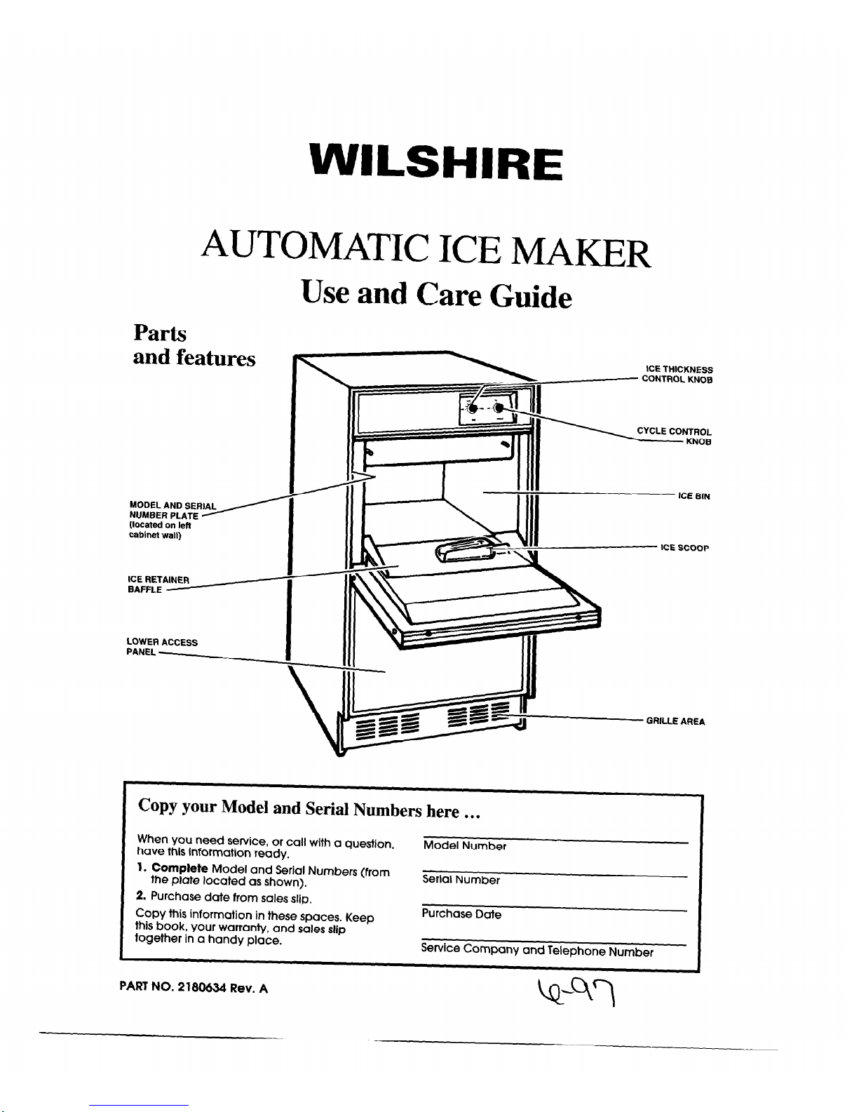
Parts
and features
NUMBER PLATE A----
MODEL AND SERIAL
(located on left
cabinet wall)
ICE RETAINER
BAFFLE
LOWER ACCESS
PANEL -
ICE THICKNESS
c_c_ CONTROL KNOB
M
CYCLE CONTROL
r
KNOB
r
!J
GRILLE AREA
Copy your Model and Serial Numbers here . . .
When you need service, or call with a question,
have this information ready.
Model Number
1.
Complete
Model and Serial Numbers (from
the plate located as shown).
Serial Number
2. Purchase date from sales slip.
Copy this information in these spaces.
Keep
this book, your warranty, and sales slip
together in a handy place.
Purchase Date
Service Company and Telephone Number
PART NO. 2180634 Rev. A
Page 2
Contents
Page
ICE MAKER SAFETY ............................................... 2-3
USING YOUR ICE MAKER ......................................... 4
How the Ice Maker Works ....................................... .4
Setting the Controls ................................................ .4
Changing the Bin Door Panel .................................. 5
Changing the Lower Access Panel .......................... 6
CLEANING AND CARING FOR
YOUR ICE MAKER ......................................................
7
Cleaning Exterior Surfaces
.....................................
.7
Page
Cleaning the Condenser ....................................... .7
Cleaning the Ice Maker System ............................. 8
Cleaning the Interior Components ........................ .9
Filtering and Treating Water ................................ 10
VACATION AND MOVING CARE
............................. 10
IF YOU NEED SERVICE OR ASSISTANCE
............. 11
Before Calling for Service .................................... 11
WARRANTY
...............................................................
12
Ice Maker Safety
Your safety and the safety of others is very important.
We have provided many important safety messages in this manual and on your appliance. Always read and obey all
safety messages.
This is the safety alert symbol.
This symbol alerts you to hazards that can kill or hurt you and others.
All safety messages will be preceded by the safety alert symbol and the word “DANGER” or
“WARNING.” These words mean:
You )viJl be killed or seriously injured if you don’t
follow instructions.
You can be killed or seriously injured if you don’t
follow instructions.
All safety messages will identify the hazard, tell you how to reduce the chance of injury, and tell you what can happen
if the instructions are not followed.
IMPORTANT SAFETY INSTRUCTIONS
WARNING
- To reduce the risk of fire, electric shock, or injury when using your ice maker, follow these basic
precautions:
l Plug into grounded 3 prong outlet.
*Disconnect power before cleaning.
l Do not remove ground prong.
.Disconnect power before servicing.
l Do not use an adapter.
*Replace all panels before operating.
l Do not use an extension cord.
l use two or more people to move or install ice maker.
- SAVE THESE INSTRUCTIONS -
Page 3
It is your responsibility to make sure the
ice maker:
l
is installed and properly leveled where it is protected
from the elements.
l
is located so that the front is not blocked to restrict airflow.
l
is located in a well ventilated area with temperatures
above 55°F (13°C) and below 110°F (43°C). Best results
are obtained at temperatures between 70°F (21 “C) and
90°F (32°C).
l
is properly connected to a water supply and drain.
l
is properly connected to electricity. A 115 Volt, 60 Hz., AC
only, 15 or 20 ampere electrical supply circuit, properly
grounded in accordance with the National
Electrical Code and local codes and ordinances,
is required.
NOTE:
A time delay fuse or circuit breaker is
recommended.
l
is not used by anyone unable to operate it
properly.
l
is used only to do what ice makers are designed
to do.
l
is properly maintained.
ELECTRICAL REQUIREMENTS
A 115 Volt, 60 Hz., AC only, 15 or 20 ampere electrical
supply circuit, properly grounded in accordance with the
National Electrical Code and local codes and ordinances,
is required.
It is recommended that a separate circuit, serving only this
appliance, be provided. Use a receptacle which cannot
be turned off with a switch or pull chain.
Electrical Shock Hazard
Plug into a grounded 3 prong outlet.
Do not remove ground prong.
Do not use an adapter.
Do not use an extension cord.
Failure to follow these instructions can result in
death, fire, or electrical shock.
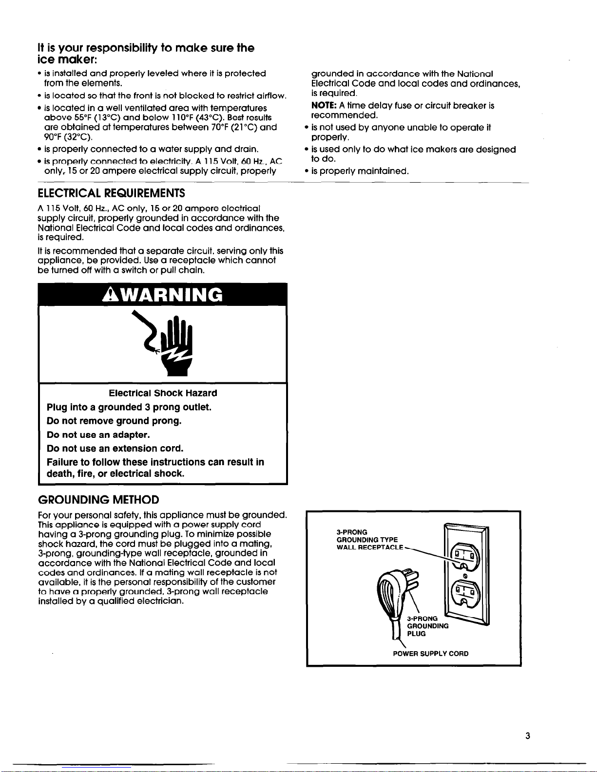
GROUNDING METHOD
For your personal safety, this appliance must be grounded.
This appliance is equipped with a power supply cord
having a 3-prong grounding plug. To minimize possible
shock hazard, the cord must be plugged into a mating,
3-prong, grounding-type wall receptacle, grounded in
accordance with the National Electrical Code and local
codes and ordinances. If a mating wall receptacle is not
available, it is the personal responsibility of the customer
to have a properly grounded, 3-prong wall receptacle
installed by a qualified electrician.
3-PRONG
GROUNDING TYPE
WALL RECEPTACLE
POWER SUPPLY CORD
3
Page 4
Using your ice maker
How the ice maker works
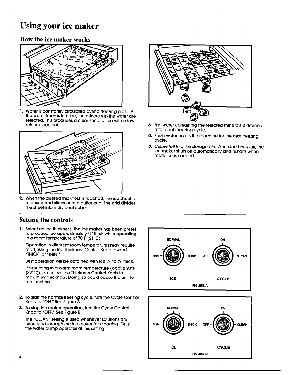
1. Water is constantly circulated over a freezing plate. As
the water freezes into ice, the minerals in the water are
rejected. This produces a clear sheet of ice with a low
mineral content.
2. When the desired thickness is reached, the ice sheet is
released and slides onto a cutter grid. The grid divides
the sheet into individual cubes.
3. The water containing the rejected minerals is drained
after each freezing cycle.
4. Fresh water enters the machine for the next freezing
cycle.
5. Cubes fall into the storage bin. When the bin is full, the
ice maker shuts off automatically and restarts when
more ice is needed.
Setting the controls
1. Select an ice thickness. The ice maker has been preset
to produce ice approximately I/Z” thick while operating
in a room temperature of 70°F (21°C).
Operation in different room temperatures may require
readjusting the Ice Thickness Control Knob toward
“THICK” or “THIN.”
Best operation will be obtained with ice %” to %” thick.
If operating in a warm room temperature (above 90°F
(32°C)) do not set Ice Thickness Control Knob to
maximum thickness. Doing so could cause the unit to
malfunction.
2. To star-l the normal freezing cycle, turn the Cycle Control
Knob to “ON.” See Figure A.
3. To stop ice maker operation, turn the Cycle Control
Knob to “OFF.” See Figure B.
The “CLEAN” setting is used whenever solutions are
circulated through the ice maker for cleaning. Only
the water pump operates at this setting.
NORMAL
ON
I
THICK OFF -
- CLEAN
I
ICE
CYCLE
FIGURE A
I
NORMAL
ON
I
-THICK OFF-
- CLEAN
4
I
ICE
CYCLE
FIGURE B
Page 5

Changing the bin door panel
All models, except those with stainless steel fronts, are
equipped with doublesided decorator panels for both the
bin door and the lower access panel. The panels are either
black/white or almond/harvest gold.
You can also make custom panels to match your existing
cabinets.
To change the bin door panel (Style 1):
1.
Open the storage bin door and remove the 2 screws on
top of the door. These screws hold the handle in place.
2. Loosen the screws in both side trim pieces.
3. Remove the handle and the handle insert. Proceed to
step 4.
To change the bin door panel (Style 2):
1.
Open the storage bin door and remove the 2 screws
on
top of the door. These screws hold the handle in place.
2. Loosen the screws in both side trim pieces.
3. Remove the handle.
4. Carefully slide out the decorator panel and reassemble
with the selected surface facing out. Be careful not to
scratch the panel as it is inserted. See figure in right
column.
NOTE:
To use a custom panel, remove the decorator
panel, and the styrofoam door insulation. Break off all
of the ribs on the door insulation. This step is needed to
allow for the custom panel thickness. The custom panel
should be l/41’ (6 mm) thick.
l
For door
Style
1:
The custom panel should be
17” wide x 1 l-14%” tall (433 mm x 286 mm).
l
For door
Style 2: The custom panel should be
17” wide x 13%” tall (433 mm x 335 mm).
Reinstall the modified door insulation in the door
assembly, and slide the custom panel between the
front trims and the insulation. Be careful not to scratch
the custom panel as it is inserted.
5. Replace the handle, handle insert (on some models),
and screws. Tighten the handle and side trim screws.
1 STYLE1
HANDLE
SCREWS
(both
sides)
STYLE 2
DECORATOR
5
Page 6

Changing the lower access panel
Electrical Shock Hazard
Disconnect power before servicing.
Replace all panels before operating.
Failure to do so can result in death or electrical shock.
1. Unplug ice maker or disconnect power.
2. Remove the 2 screws in the lower access panel and the
1 screw from the center of the front panel support.
(Open the door slightly for better access to the screw.)
Pull the bottom forward and then pull down to remove
the lower access panel.
SUPPORT ’
3. Remove the 2 screws from the top panel trim and
remove the top trim.
DECORATOR
4. Carefully slide out the decorator panel and reassemble
with the selected surface out. Be careful not to scratch
the panel as it is inserted. See figure above.
NOTE:
To use a custom panel, remove the decorator
panel and both of the cardboard spacers. This step
is needed to allow for the custom panel thickness.
The custom panel should be l/4” (6 mm) thick and
17” wide x 11 15/~6” tall (433 mm x 303 mm). Slide the
custom panel between the front trims and the rear
panel of the lower panel assembly. Be careful not to
scratch the custom panel as it is inserted.
5. Replace the top trim and screws.
6. Reinstall the lower access panel assembly and screws.
7. Plug in ice maker or reconnect power.
Page 7

Cleaning and caring for your ice maker
Periodically inspect and clean the ice maker to keep it
operating at peak efficiency and to prevent premature
Clean the ice and water systems periodically
failure of system components.
to remove mineral scale buildup. Frequency of
cleaning depends on water hardness. With water
Both the ice making system and the air-cooled con-
denser need to be cleaned regularly.
The minerals rejected from the circulating water during
the freezing cycle will eventually form a hard, scaly
deposit in the water system which prevents a rapid
release of the ice from the freezing plate.
that contains few impurities, cleaning may not be
required for several years. With hard water (15 to 20
grains/gallon), cleaning may be required as frequently as every 6 months.
Cleaning exterior surfaces
Wash the exterior painted surfaces and gaskets with
warm water and mild soap or detergent. Wipe and dry.
Regular use of a good household appliance cleaner
and wax will help protect the finish.
Do not use harsh or abrasive cleaners on the enamel
surfaces. They may scratch the finish.
Cleaning the condenser
Electrical Shock Hazard
Disconnect power before cleaning.
Replace all panels before operating.
Failure to do so can result in death or electrical shock.
A dirty or clogged condenser:
l
prevents proper airflow.
l
reduces ice making capacity.
l
causes higher than recommended operating
temperatures which may lead to component failure.
1.
Unplug ice maker or disconnect power.
4. Remove dirt and lint from the condenser fins and
the unit compartment with a brush attachment
connected to a vacuum cleaner. Condenser fins
can bend easily. Use care when vacuuming the
condenser to keep from bending fins.
5. Replace the grilled front panel and screws.
6. Plug in ice maker or reconnect power.
7
2. Remove the 2 screws in the lower access panel and
the 1 screw from the center of the front panel support.
(Open bin door slightly for better access to screw.)
3. Pull the bottom forward and then pull down to remove
the lower access panel.
Page 8

Cleaning the ice maker system
1. Place the Cycle Control Knob in the “OFF” position.
2. Remove the 2 thumb screws, and slide the ice cutter
grid forward, out of the 2 slots near the water pan. Any
ice on the grid should be melted under running warm
water. Attempting to pick the ice slab from the grid may
stretch and damage the grid wires.
3. Unplug the electrical harness.
4. Remove all ice from the storage bin and the
freezing plate.
DRAIN
PLUG
5. Drain the water pan by removing the drain plug.
When finished, replace the drain plug.
CLEAN
Commercial ice machine cleaners are also available
in liquid form and should be mixed according to
instructions on the label.
FREEZING PLATE
7. Pour cleaning solution into water pan and turn the
Cycle Control Knob to “CLEAN.” If solution foams
while pouring, stop until foaming subsides, then add
balance of solution. Allow solution to circulate until
scale has dissolved. The circulating solution may not
contact scale on the side flanges of the freezing plate.
To remove this scale, wear rubber gloves and use a
stainless steel sponge or pad dipped in cleaning
solution to scrub the side flanges until scale is removed. Generally scale will be dissolved in 15 to 30
minutes. Severe scale formation may require repeating the cleaning process with a fresh quantity of
solution if the scale has not dissolved after 30 minutes.
8. Turn the Cycle Control Knob to “OFF” and drain.
9. Follow cleaning with 2 fresh water rinses, circulating
each rinse for 5 minutes, and drain.
10. This completes the “in place” cleaning and sanitizing
of the water system and freezing plate. Other interior
components must also be cleaned and sanitized.
6. Pour 2 quarts (2 L) of hot water into the water pan and
turn the Cycle Control Knob to “CLEAN.” This step warms
up the system and allows the cleaning solution to be
more effective. Allow to circulate 5 minutes. Turn the
Cycle Control Knob to “OFF” and drain. Prepare the
cleaning solution by thoroughly mixing 6 oz. (170 g) of
powdered citric acid or phosphoric acid into 2 quarts
(2 L) of hot water.
8
Page 9

Cleaning the interior components
Electrical Shock Hazard
Disconnect power before cleaning.
Replace all panels before operating.
Failure to do so can result in death or electrical shock.
1.
Unplug ice maker or disconnect power.
2. Open the storage bin door and remove any ice that is
in the bin.
3. Remove the ice retainer baffle by flexing it and sliding if
off the studs.
4. Remove the ice cutter grid by unscrewing the 2 thumb
screws, sliding the grid forward, and unplugging the
electrical wire harness.
5. Remove the water pan by unscrewing the
2 thumb screws.
END CAPS
7. Remove the water distributor from the freezing
plate. It is held in place by rubber end caps,
Remove the inlet hose and clean all water
distributor holes and the small orifice in the inlet
side of the water distributor. When replacing the
water distributor, make sure the end caps are
located in the freezing plate holes and that the
water distributor holes face down.
8. Wash the
interior components
(ice retainer
baffle, cutter grid, water pan, inlet hose, and
water distributor) and the storage bin, door
gasket, and ice scoop with mild soap or
detergent and warm water. Rinse in clean
water. The components should also be cleaned
in a solution of 1 tablespoon (15 mL) of house
hold bleach mixed with 1 gallon (3.8 L) warm
water.
DO NOT WASH PLASTIC PARTS IN THE
DISHWASHER. They cannot withstand
temperatures above 145°F (63°C).
9. Replace the interior components (water distributor, inlet hose, water pan, cutter grid, and ice
retainer baffle).
10.
Check the following:
l
Hose from water valve is in the water pan.
l
Rubber drain plug is in the water pan.
l
Water distributor is seated and holes are
facing down.
l
Hose is connected to the pump and the
water distributor.
l
Hose from water pan is inserted into the
storage bin drain opening.
11.
Reconnect the electrical harness, and slide
cutter grid into place. Tighten the thumb screws.
12. Plug in ice maker or reconnect power.
13. Reset the controls, see “Setting the controls” on
page 4.
6. Remove the hose from the water pump.
9 1
Page 10

Filtering and treating water
In some areas, it may be beneficial to filter or treat the
water being supplied to the ice maker. It can improve the
reliability of the machine, reduce water system maintenance, and produce a better quality of ice.
The installation of a polyphosphate feeder will generally
reduce scale buildup, and the ice maker will require less
frequent cleaning.
For information about filtering and treating the water, see
the dealer from whom you purchased your ice maker.
Vacation and moving care
Electrical Shock Hazard
Disconnect power before servicing.
Replace all panels before operating.
Failure to do so can result in death or electrical shock.
To shut down the ice maker:
1. Unplug ice maker or disconnect power.
2. Remove all ice from the storage bin.
3. Shut off the water supply.
4. Remove the 2 screws in the lower grille area and the
1 screw from the center of the front panel support.
(Open bin door slightly for better access to screw.) Pull
the bottom forward and down then pull to remove the
lower access panel.
5. Disconnect the inlet and outlet hoses to the water valve.
Allow these hoses to drain, then reconnect them to
the valve.
6. Replace the lower access panel and screws.
I
I //I i
INLET
7. Drain water from water pan by removing drain plug.
Also, remove water from drain line.
8. Before using the machine again, clean the ice maker
system, interior components, and the storage bin.
WATER PAN
9. Plug in ice maker or reconnect power.
NOTE:
All components of the ice maker are permanently lubricated at the factory. They should not require any additional
oiling throughout the normal life of the machine.
10
Page 11

If you need service or assistance, we suggest
you follow these steps:
Before calling for service . . .
Performance problems often result from little things you can
find and fix yourself, without tools of any kind.
Unit does not run:
l
Cycle Control Knob must be in the “ON” position,
l
Check to see that the power cord is plugged in.
l
Check for a blown fuse or tripped circuit breaker in the
electrical supply to the machine.
l
Room temperatures must be above 55°F (13°C). Otherwise,
the Bin Thermostat may sense a cold room temperature
and shut off even though the storage bin is not full of ice.
Also, the unit may not restart once it does shut off.
Unit runs but does not produce ice:
l
Cycle Control Knob must be in the “ON” position.
l
Check water supply to make sure it is open.
l
If ice maker is to be operated at an elevation of 2,000 feet
(600 m) or more above sea level, both the Bin Thermostat
and the Ice Thickness Thermostat will need to be
recalibrated. Call your dealer or an authorized service
group to have the necessary changes made.
Unit runs but produces very little ice:
l
Room temperature may be extremely high (over 90°F
(32°C)). In this case, it is normal for ice production to
be low.
l
Dirt or lint may be blocking the air flow through the finned
condenser. Condenser needs to be cleaned.
l
Check to see if the unit has a scale buildup in the water
and/or freezing systems. Clean them, If necessary.
Grid is not cutting ice sheets:
l
Check the grid harness plug to make sure the connection
is secure.
Off taste in ice cubes:
l
There may be an unusually high mineral content in the
water supply. Water may need to be filtered or treated.
l
Do not store any foods in the ice bin.
l
Packaging materials are not all removed.
11
Page 12

WILSHIRE CORPORATION
ICE MAKER WARRANTY
GC-535
COMPACTGRIDCUBER
I. Subject to the limitations herein set forth, Wilshire warrants to the original user of the ice
maker that its component parts will be free from defects in material and workmanship for
a period of either twelve months from date of start-up, provided registration card is
returned, or fifteen months from date of original shipment from Whilshire’s factory, if
warranty registration card is not returned.
II. Wilshire’s obligation hereunder shall be limited to repairing or exchanging, at its election,
a defective part which is returned freight prepaid to Wilshire’s authorized parts agency,
provided that examination proves to its satisfaction that the defect was not caused by
accident, misuse, negligence, alteration, vandalism, fire, flood, or other acts of God.
Wilshire will not be responsible for the repaired or exchanged labor or for the removal or
installation of any part outside of its factory. Wilshire reserves the right to make a repair or
replacement charge when its inspection indicates that the part returned to it was not
defective in workmanship or material.
III. This warranty is Wilshire’s sole obligation in respect of the ice maker warranted hereunder.
Wilshire shall not be liable for consequential or loss of use damages nor for damages due
to injury to person or property. No person is authorized to assume for Wilshire any obligation
or liability other than those expressly assumed hereunder.
PART NO. 2 180634 Rev. A
8 1997 Whirlpool U.S.A.
4/97
Printed in U.S.A.
 Loading...