

Page 1
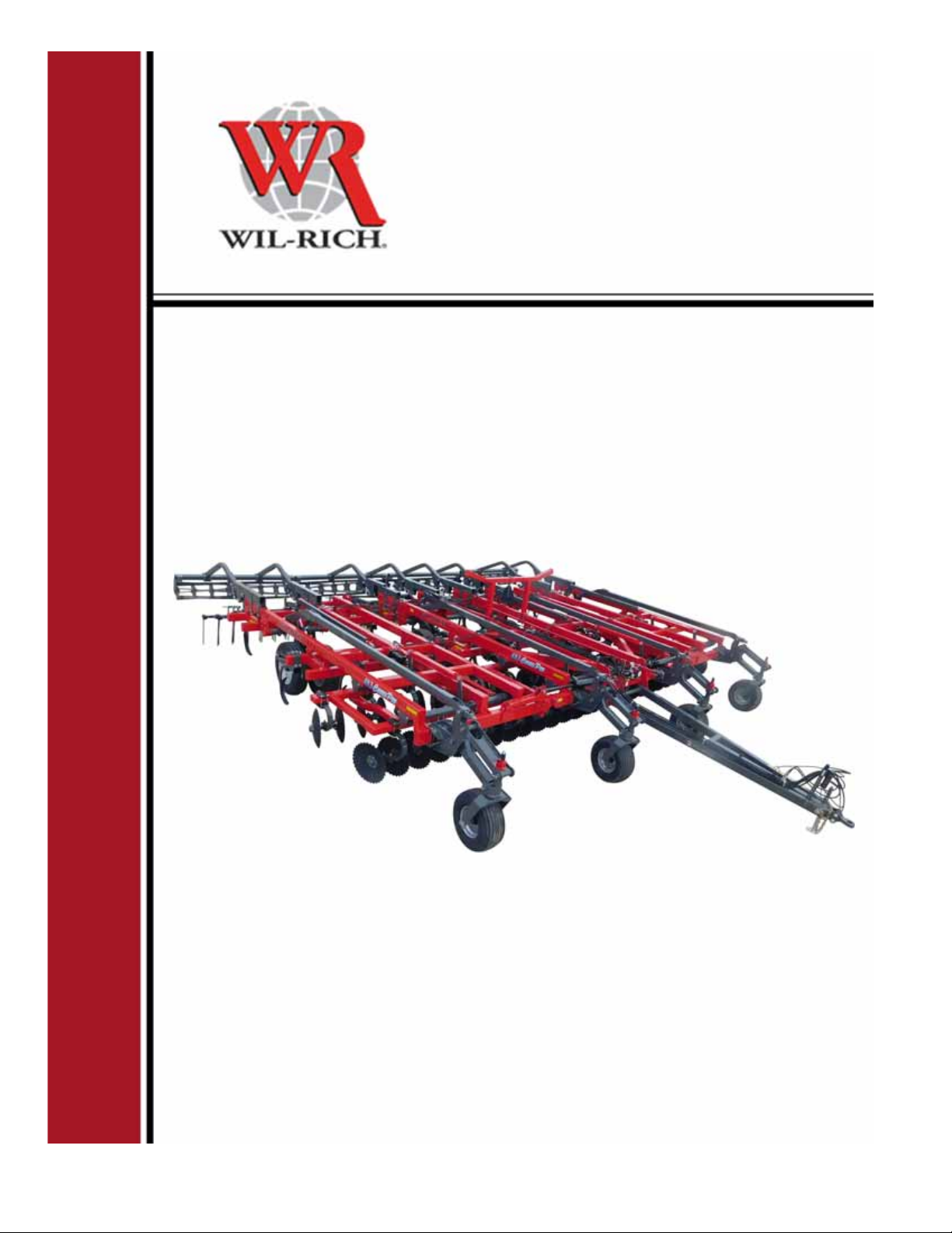
Operator’s Manual
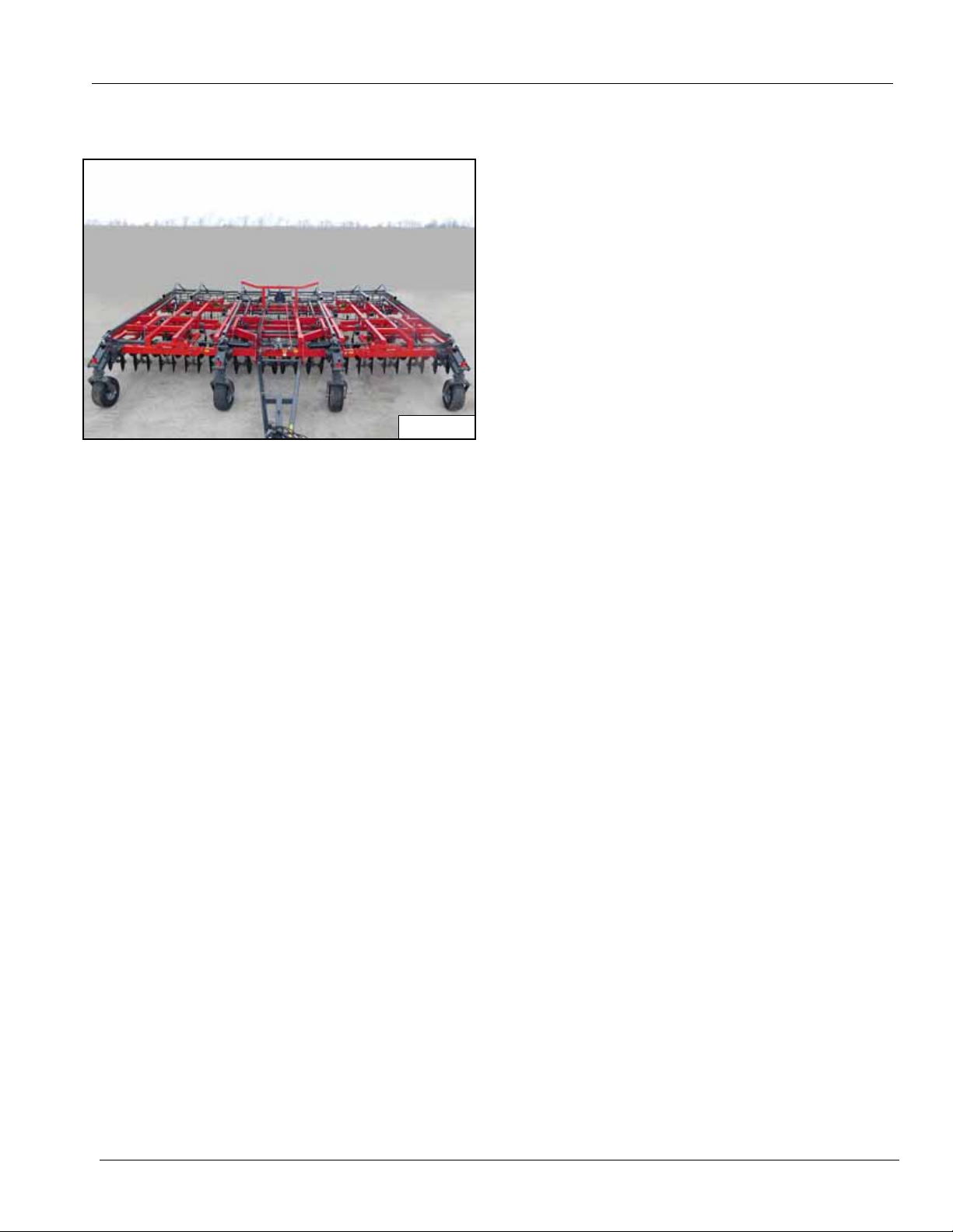
483 Chisel Pro
July 2015
08-19 | 79993
Page 2

Page 3
WARRANTY
AGCO-Amity JV LLC Limited Warranty Terms And Conditions - United States and Canada
Effective For Equipment Retailed And Delivered After June 1, 2018
WHAT IS WARRANTED: AGCO Amity JV warrants its new equipment to be free of defects in material and workmanship at the time of
delivery to the first retail purchaser, renter, or lessee. These terms apply to all Wishek, Wil-Rich, and Amity brands of new equipment
originally marketed in the United States and Canada
Warranty Period
12 Months from the date of delivery to the first retail purchaser, renter or lessee
483 Disk Chisel, Field Cultivator, and Disk Cultivators: 3 years on main frames, wing frames, and shank assemblies
Precision Shank Drill: 3 years on main frame, wing frame, and rockshafts.
EXCEPTIONS FROM THIS WARRANTY
Freight Charges
Improvements, Changes, or Disconti n uance AGCO Amity JV reserves the right to make changes and improvements in design
or changes in specifications at any time to any product without incurring any obligations to owners of products previously sold.
Repairs and Maintenance Not Covered Under Warranty - This warranty does not cover conditions resulting from misuse,
natural calamities, use of non-AGCO-Amity JV parts, negligence, alteration, accident, use of unapproved attachments, usage which
is contrary to the intended purposes, or conditions caused by failure to perform required maintenance. Replacement of Wear or
Maintenance items (unless defective) such as but not limited to, filters, hoses, belts, lubricants, light bulbs, wheel alignment,
tightening of nuts, belts, bolts, and fittings, service tune-up, computer parameter adjustments and general adjustments which may
from time to time be required are not covered.
Rubber Tire Warranty - Rubber tires are warranted directly by the respective manufacturer only and not by AGCO Amity JV.
Satellite Outages - Interruptions in satellite interfaces and satellite communications are outside the control of this product and are
not covered by this warranty. The company is not responsible for issues or degradation of system performance resulting from such
interruptions in satellite interfaces and satellite communications where the issues are not related to defects in this product.
- This warranty does not cover freight charges.
OWNER’S OBLIGATION
It is the responsibility of the Owner to transport the equipment or parts to the service shop of an authorized AGCO Amity JV Dealer or
alternatively to reimburse the Dealer for any travel or transportation expense involved in fulfilling this warranty. This Warranty does NOT
cover rental of replacement equipment during the repair period, damage to products which have been declared a total loss and
subsequently salvaged, overtime labor charges, freight charges for replacement parts, or special handling requirements (such as, but not
limited to, the use of cranes).
EXCLUSIVE EFFECT OF WARRANTY AND LIMITATION OF LIABILITY
THIS WARRANTY IS IN LIEU OF ALL WARRANTIES OF MERCHANTABILITY, FITNESS FOR A PUPROSE OR OTHER
REPRESENTATIONS, WARRANTIES OR CONDITIONS, EXPRESS OR IMPLIED. The remedies of the Owner set forth herein are
exclusive. The Company neither assumes nor authorizes any person to assume for it any other obligation or liability in connection with the
sale of covered machines. Correction of defects, in the manner and for applicable period of time provided above, shall constitute fulfillment
of all responsibilities of AGCO Amity JV to the Owner, and AGCO Amity JV shall not be liable for negligence under contract or in any
manner with respect to such machines. IN NO EVENT SHALL THE OWNER BE ENTITLED TO RECOVER FOR INCIDENTAL, SPECIAL
OR CONSQUENTIAL DAMAGES SUCH AS BUT NOT LIMITED TO, LOSS OF CROPS, LOSS OF PROFITS OR REVENUE, OTHER
COMMERCIAL LOSSES, INCONVENIENCE OR COST OF RENTAL OR REPLACEMENT EUQIPMENT.
Some states or Provinces do not permit limitations or exclusions of implied warranties or incidental or consequential damages, so the
limitations or exclusions in this warranty may not apply.
“AGCO Amity JV” AS REFERRED TO HEREIN WITH RESPECT TO SALES IN: UNITED STATES and CANADA: AGCO Amity JV LLC
PO Box 1030
Wahpeton, ND 58074
79993 | 08-19 1
Page 4
WARRANTY
AGCO-Amity JV LLC Limited Warranty Terms And Conditions - United States and Canada
Effective For Equipment Retailed And Delivered After June 1, 2018
Additional Warranty Information
New Equipment Warranty: Equipment is eligible for warranty service only if it qualifies under the provisions of the New Equipment
Warranty. The selling dealer will deliver this Warranty to the original retail purchaser at the time of sale, and the dealer will register the sale
and Warranty with AGCO Amity JV LLC.
Subsequent Owners: This Warranty covers the first retail purchaser and all subsequent owners of the equipment during the specified
warranty period. Should the AGCO Amity JV Dealer sell this equipment to a subsequent owner, the Dealer must deliver the warranty
document to the subsequent owner so the subsequent owner can register ownership with AGCO Amity JV and obtain the remaining
warranty benefits, if av ailab le, with no intermission in the W arranty P eriod. Subsequent Owner Procedure will apply. It is the responsibility of
the subsequent owner to transport the equipment to the service shop of an authorized AGCO Amity JV Dealer or alternatively to reimburse
the Dealer for any travel or transportation expensed involved in fulfilling this warranty. This Warranty does NOT cover changes for rental or
replacement equipment during the repair period, products which have declared a total loss and subsequently salvaged, overtime labor
charges, freight charges for replacement parts, or units sold at auction.
Warranty Service - To be covered by Warranty, service must be performed by an authorized AGCO Amity JV Dealer. It is recommended
that you obtain warranty service from the Dealer who sold you the equipment because of that Dealer’ s continued interest in y ou as a v alued
customer. In the event this is not possible, warranty service may be performed by any other authorized AGCO Amity JV Dealers in the
United States or Canada. It is the responsibility of the Owner to transport the equipment to the service shop of an authorized AGCO Amity
JV Dealer or alternatively to reimburse the Dealer for any travel or transportation expense involved in fulfilling this warranty.
Maintenance Service - The Owner’s Manual furnished to you with the equipment at the time of delivery contains important maintenance
and service information. You must read this manual carefully and follow all the maintenance and service recommendations. Doing so will
result in greater satisfaction with your equipment and help avoid service and warranty problems. Please remember that failures due to
improper maintenance of your equipment are not covered by warranty.
Maintenance Inspections - To insure the continued best performance from your agricultural equipment, we recommend that you
arrange to make your equipment available to your selling Dealer for a maintenance inspection 30 days prior to warranty expiration.
2 79993 | 08-19
Page 5

TABLE OF CONTENTS
WARRANTY . . . . . . . . . . . . . . . . . . . . . . . . . . . . . . . . . . . . . . . . . . . . . . . . . . . . . . . . . . . . . . . .1
FOREWORD . . . . . . . . . . . . . . . . . . . . . . . . . . . . . . . . . . . . . . . . . . . . . . . . . . . . . . . . . . . . . . .5
To The Owner . . . . . . . . . . . . . . . . . . . . . . . . . . . . . . . . . . . . . . . . . . . . . . . . . . . . . . . . . . . .5
Serial Number . . . . . . . . . . . . . . . . . . . . . . . . . . . . . . . . . . . . . . . . . . . . . . . . . . . . . . . . . . . .5
Disclaimer . . . . . . . . . . . . . . . . . . . . . . . . . . . . . . . . . . . . . . . . . . . . . . . . . . . . . . . . . . . . . . .5
SAFETY . . . . . . . . . . . . . . . . . . . . . . . . . . . . . . . . . . . . . . . . . . . . . . . . . . . . . . . . . . . . . . . . . . .7
Safety Information . . . . . . . . . . . . . . . . . . . . . . . . . . . . . . . . . . . . . . . . . . . . . . . . . . . . . . . . .7
General Safety Practices . . . . . . . . . . . . . . . . . . . . . . . . . . . . . . . . . . . . . . . . . . . . . . . . . . .7
Safety During Transportation . . . . . . . . . . . . . . . . . . . . . . . . . . . . . . . . . . . . . . . . . . . . . . . .7
Safety Decals . . . . . . . . . . . . . . . . . . . . . . . . . . . . . . . . . . . . . . . . . . . . . . . . . . . . . . . . . . . .8
Safety Lighting . . . . . . . . . . . . . . . . . . . . . . . . . . . . . . . . . . . . . . . . . . . . . . . . . . . . . . . . . .16
Operation Safety . . . . . . . . . . . . . . . . . . . . . . . . . . . . . . . . . . . . . . . . . . . . . . . . . . . . . . . . .17
General Maintenance Safety Practices . . . . . . . . . . . . . . . . . . . . . . . . . . . . . . . . . . . . . . . .17
Hydraulic Safety . . . . . . . . . . . . . . . . . . . . . . . . . . . . . . . . . . . . . . . . . . . . . . . . . . . . . . . . .18
Hydraulic Connection Torques . . . . . . . . . . . . . . . . . . . . . . . . . . . . . . . . . . . . . . . . . . . . . .18
Transporting Safety . . . . . . . . . . . . . . . . . . . . . . . . . . . . . . . . . . . . . . . . . . . . . . . . . . . . . . .19
PREPARATION . . . . . . . . . . . . . . . . . . . . . . . . . . . . . . . . . . . . . . . . . . . . . . . . . . . . . . . . . . . .21
CONNECTING THE IMPLEMENT . . . . . . . . . . . . . . . . . . . . . . . . . . . . . . . . . . . . . . . . . . . . . .25
OPERATION . . . . . . . . . . . . . . . . . . . . . . . . . . . . . . . . . . . . . . . . . . . . . . . . . . . . . . . . . . . . . . .27
Transporting . . . . . . . . . . . . . . . . . . . . . . . . . . . . . . . . . . . . . . . . . . . . . . . . . . . . . . . . . . . .27
Field Operation Preparation . . . . . . . . . . . . . . . . . . . . . . . . . . . . . . . . . . . . . . . . . . . . . . . .28
Field Operation Leveling Adjustments . . . . . . . . . . . . . . . . . . . . . . . . . . . . . . . . . . . . . . . .29
Field Operation Settings . . . . . . . . . . . . . . . . . . . . . . . . . . . . . . . . . . . . . . . . . . . . . . . . . . .30
MAINTENANCE . . . . . . . . . . . . . . . . . . . . . . . . . . . . . . . . . . . . . . . . . . . . . . . . . . . . . . . . . . . .35
Daily . . . . . . . . . . . . . . . . . . . . . . . . . . . . . . . . . . . . . . . . . . . . . . . . . . . . . . . . . . . . . . . . . .35
50 Hours . . . . . . . . . . . . . . . . . . . . . . . . . . . . . . . . . . . . . . . . . . . . . . . . . . . . . . . . . . . . . . .36
1000 Hours Or Yearly . . . . . . . . . . . . . . . . . . . . . . . . . . . . . . . . . . . . . . . . . . . . . . . . . . . . .37
Storage . . . . . . . . . . . . . . . . . . . . . . . . . . . . . . . . . . . . . . . . . . . . . . . . . . . . . . . . . . . . . . . .38
TROUBLESHOOTING . . . . . . . . . . . . . . . . . . . . . . . . . . . . . . . . . . . . . . . . . . . . . . . . . . . . . . .39
Troubleshooting Chart . . . . . . . . . . . . . . . . . . . . . . . . . . . . . . . . . . . . . . . . . . . . . . . . . . . . .39
79993 | 08-19 3
Page 6

4 79993 | 08-19
Page 7
FOREWORD
WR0084
To The Owner
It is the responsibility of the user to read the Operator’s
Manual and comply with the safe and correct operating
procedures as pertains to the operation, lubrication and
maintenance of the product according to the information
outlined in the Operator’s Manual.
If this machine is used by an employee or is loaned or
rented, make certain that th e operator(s), prior to using
the machine, is instructed in safe and proper use and
reviews and understands the Operator’s Manual.
The user is responsible for inspecting the machine and
for havin g parts repaired or replaced when cont inued use
of this product would cause damage or excessive wear to
the other parts.
The word NOTE is used for information that is special
such as specifications, techniques or reference
information of supplementary nature.
The word IMPORTANT is used for information that must
be read and procedures followed for the safe and proper
operation of the machine.
Serial Number
When in need of parts, always specify the model and
serial number. Write this number in the space provided.
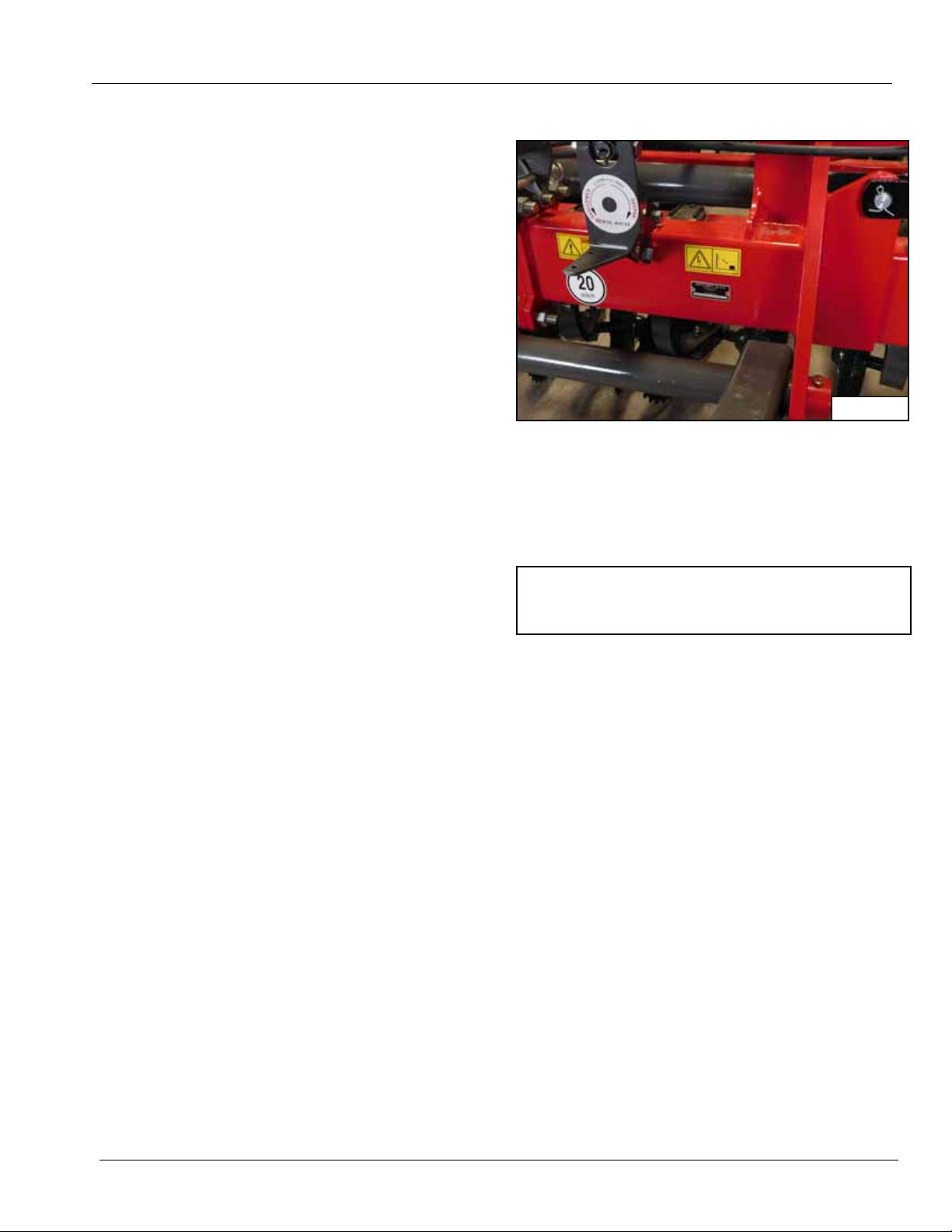
The serial number plate is located on the main frame on
the front left above the hitch frame.
Serial Number
References to the right (RH) or left (LH) on the machine
are from the operator sitting in the cab of the tractor.
Disclaimer
It is the policy of Wil-Rich to improve its products
whenever possible and practical to do so. We reserve the
right to make changes, improvements and modifications
at any time without incurring obligation to make such
changes, improvements on any equipment sold
previously.
79993 | 08-19 5
Page 8

FOREWORD
6 79993 | 08-19
Page 9

SAFETY
Safety Information
This safety alert symbol is used to alert the operator to possible danger and what to do to prevent
bodily injury. When you see this symbol it means: ATTENTION! MACHINE DAMAGE and / or YOUR
SAFETY IS INVOLVED.
WARNING: Safe practices must be f o llowed when working on or operating this equipment. All
personnel involved must:
• Read and understand the instructions in this manual.
• Be instructed in the safe use of safety devices and support stands for this machine.
• Clear the area of all personnel when connecting, moving or operating this machine.
General Safety Practices
1. READ and UNDERSTAND the Operator’s Manual before using any equipment. Review at least annually thereafter.
2. VERIFY all safety devices are in place before using any equipment.
3. KEEP all personnel away from moving parts.
4. STOP engine, place all controls in neutral, set parking brake, remove ignition key before servicing, adjusting or
maintaining.
5. BE CAREFUL when working around high pressure hydraulic system.
6. DO NOT ALLOW RIDERS.
Safety During Transportation
1. ONLY TOW at a safe speed. Use caution when making corners and meeting traffic.
2. BE AWARE that the implement is wider than the tractor when transporting.
3. ALWAYS have the wings completely folded when transporting on public roads.
4. COMPLY with local lighting, marking and oversize regulations when transporting on highways.
5. FREQUENTLY check for traffic, especially during turns.
6. INSTALL transport safety locks (See page 25).
79993 | 08-19 7
Page 10
Safety Decals
SAFETY
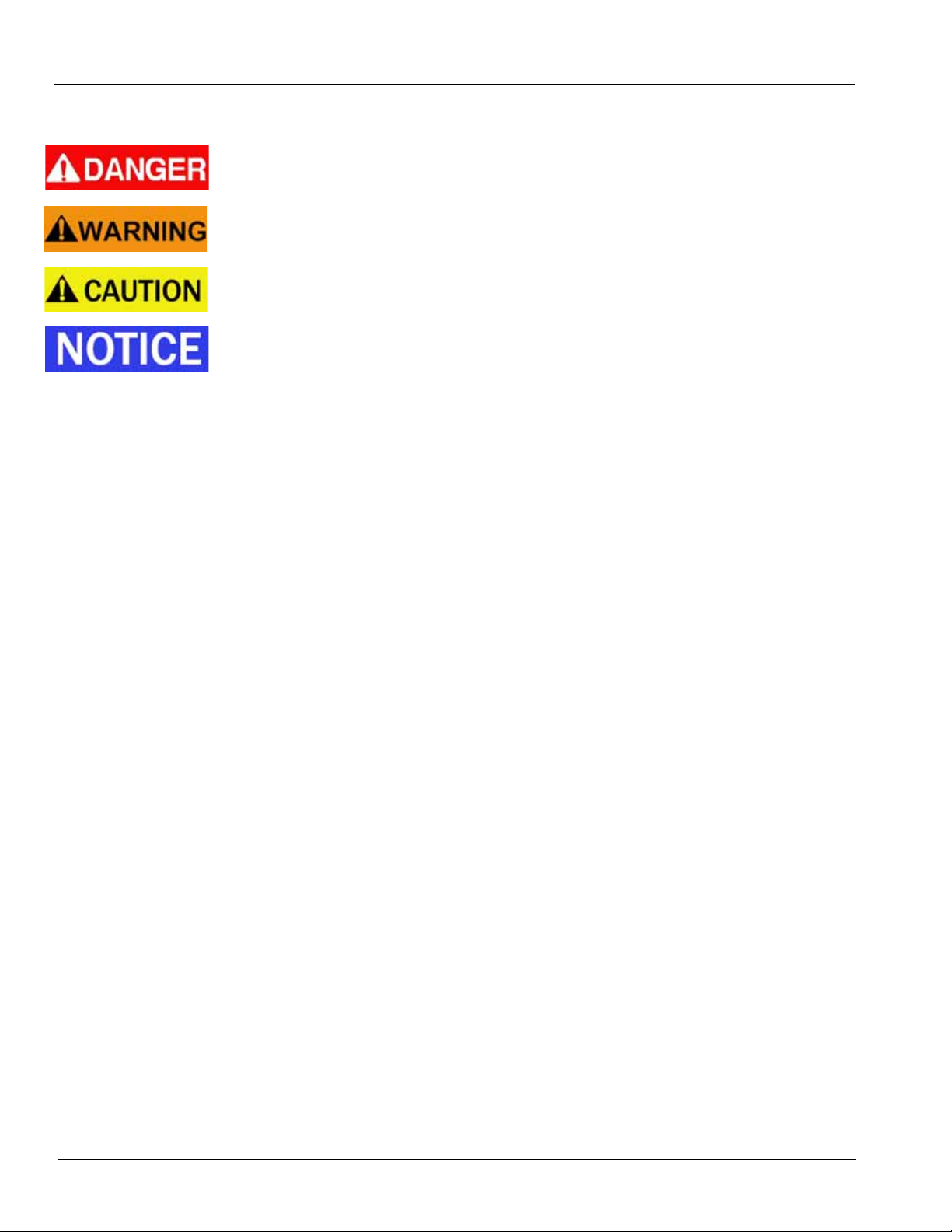
Indicates an immediate hazardous situation that will result in serious injury or death. The color
for Danger is RED.
Indicates a potentially hazardous situation that could result in death or serious injury. The color
for Warning is ORANGE.
Indicates a potentially hazardous situation that may result in minor or moderate injury. It may
also be used to alert against unsafe practices. The color for Caution is YELLOW.
The Notice decals and statements in this manual are to inform the operator of the correct fluids,
or operational practices for this machine. Failure to follow these notices will result in damage t o
the machine. The color associated with Notice is BLUE.
1. Keep safety decals clean and legible at all times.
2. Replace safety decals that are missing or have
become illegible.
3. Replaced parts that displayed a safety decals should
also display the current decals when parts are
replaced.
4. Safety decals are available from your dealer parts
department or the factory.
How to install safety signs:
1. Be sure that the installation area is clean and dry.
2. Be sure the temperature is above 50°F (10°C).
3. Decide on the exact position before removing the
backing paper.
4. Remove the smallest portion of the split backing
paper.
5. Align the sign over the specified area and carefully
press the small portion with the exposed sticky
backing in place.
6. Slowly peel back the remaining paper and carefully
smooth the remaining portion of the sign in place.
7. Small air pockets can be pierced with a pin and
smoothed out using the piece of sign backing paper.
8 79993 | 08-19
Page 11
SAFETY
WR0125
WR0126
1
WR0112
1
Safety Decal Location
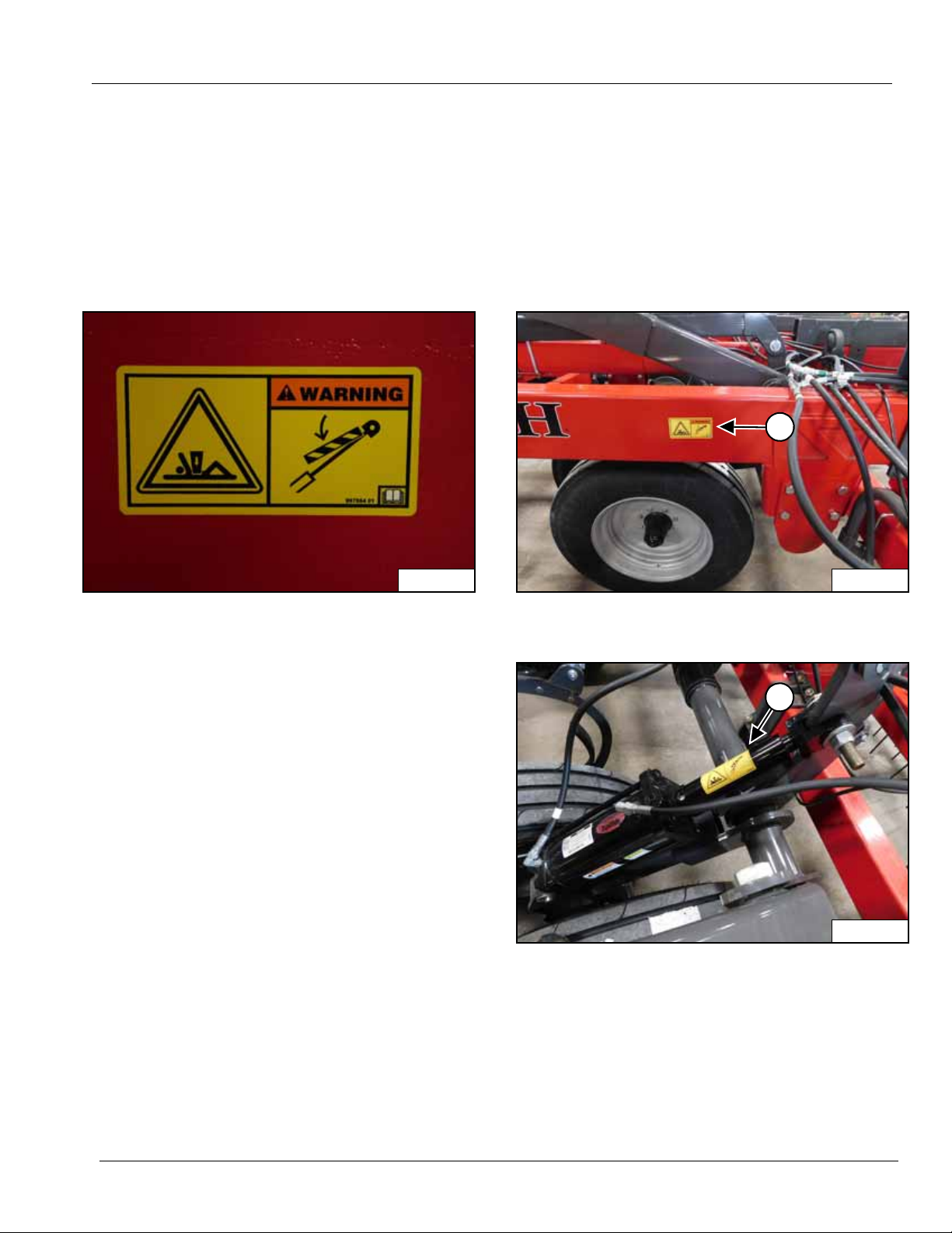
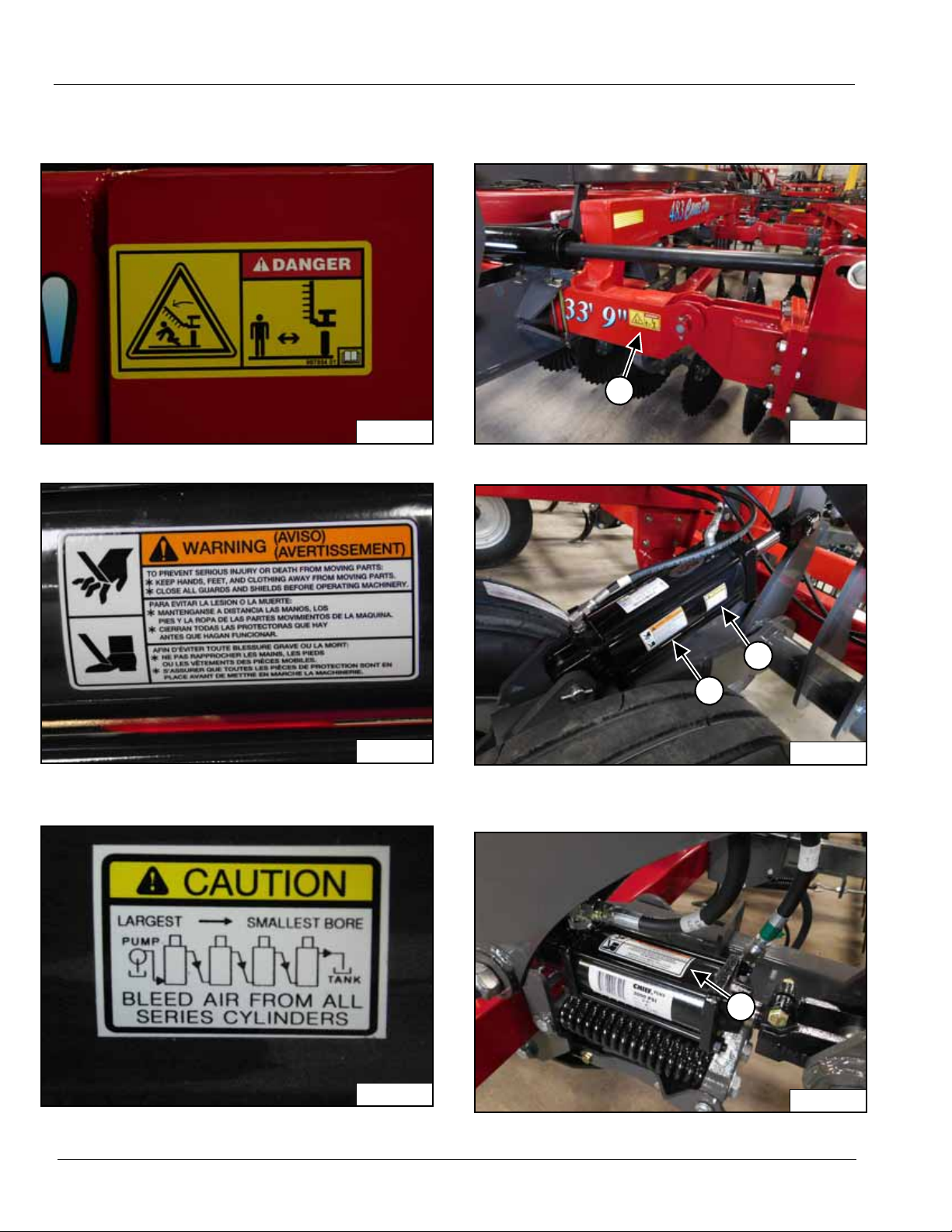
The types of safety decals and locations on the equipment are shown below. Safety requires that you familiarize yourself
with the various saf ety deca ls , the type of WARNING and the area or particular function related to that area, that requires
your SAFETY AWARNESS.
IMPORTANT: If Safety Decals have been damaged, removed, become illegible or parts replaced without safety signs,
new signs must be applied. New safety signs are available from your authorized dealer.
Safety Decals
1. WARNING - CYLINDER LOCKS MUST BE USED CRUSHING HAZARD - P/N 997864 01
Right and left sides main frame.
Right and left side transport wheel cylinder locks.
79993 | 08-19 9
Page 12
Safety Decal Location (Cont’d)
WR0091
WR0013
WR0095
WR0090
2
WR0093
3
4
WR0099
3
Safety Decals (Cont’d)
SAFETY
2. DANGER - STAND CLEAR - P/N 997854 01
3. WARNING - PREVENT SERIOUS INJURY FROM
MOVING PARTS.
Main frame left and right wing hinge.
Left and right wheel lift cylinders.
4. CAUTION - BLEED AIR FROM ALL SERIES
CYLINDERS
All rolling basket lift cylinders.
10 79993 | 08-19
Page 13

SAFETY
WR0065
WR0066
WR0077
6
5
Safety Decal Location (Cont’d)
Safety Decals (Cont’d)
5. CAUTION - Read manual before connecting - P/N
997856
6. WARNING - Read manual before disconnecting - P/N
997852
Left front main frame.
79993 | 08-19 11
Page 14
Safety Decal Location (Cont’d)
WR0067
WR0068
WR0077
7
8
WR0087
8
Safety Decals (Cont’d)
SAFETY
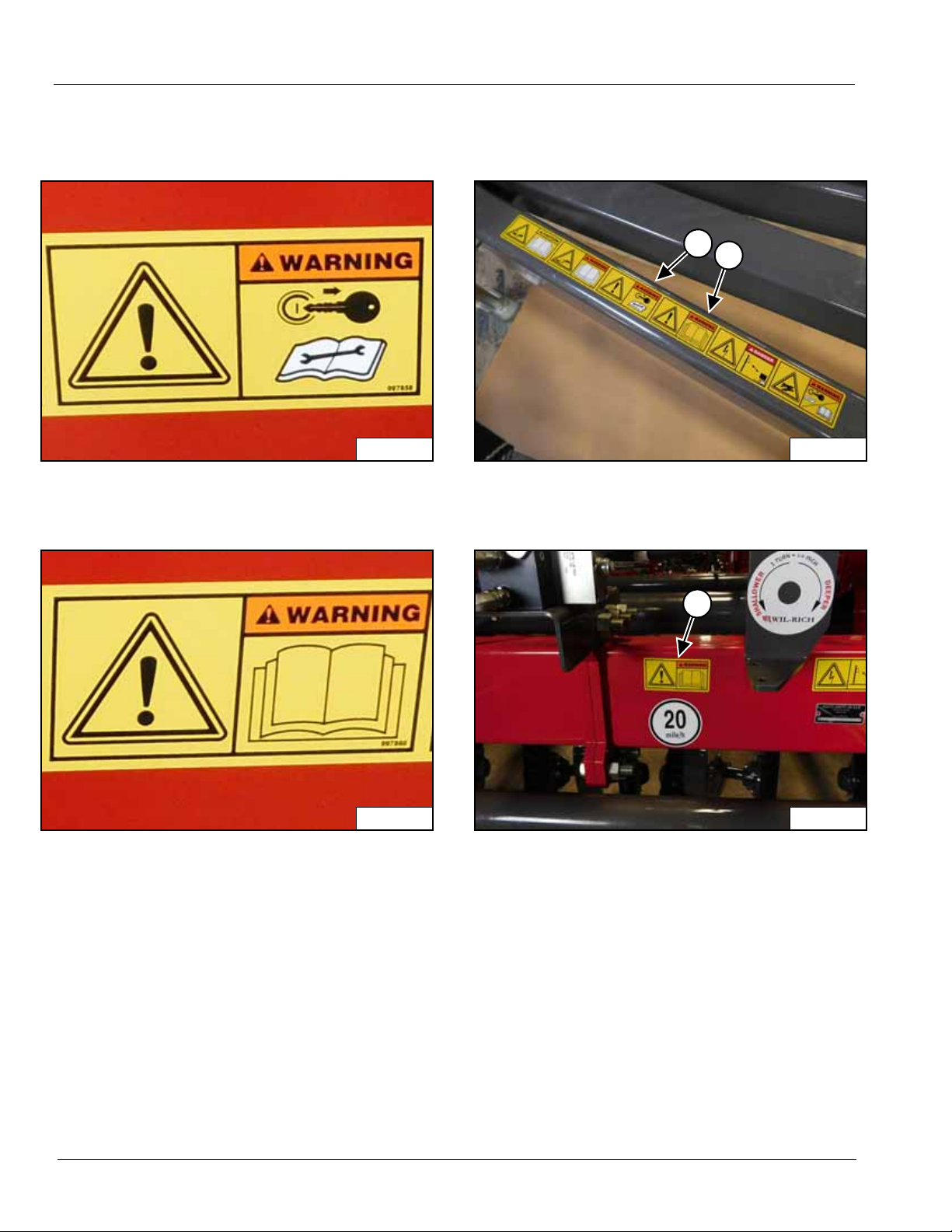
7. WARNING - Shut engine off, read manual before
maintenance - P/N 997858
8. WARNING - Read manual - P/N 997860
Left front main frame.
Left front main frame.
12 79993 | 08-19
Page 15
SAFETY
WR0069
WR0070
WR0089
WR0084
9
WR0077
10
9
WR0087
11
Safety Decal Location (Cont’d)
Safety Decals (Cont’d)
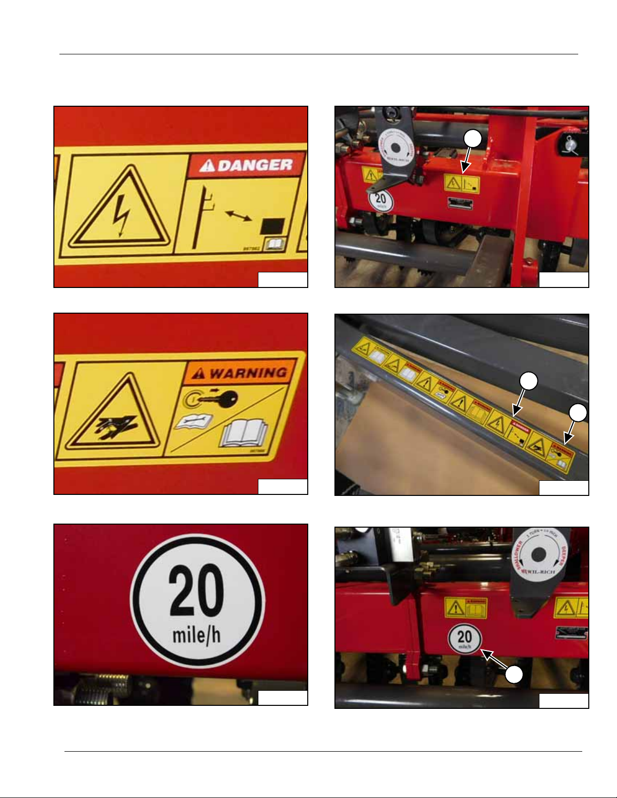
9. DANGER - Electrocution hazard - P/N 997862
10. WARNING - Hydraulic hazard - P/N 997858
Left front main frame.
Left front main frame.
11. MAXIMUM SAFE TRAVEL SPEED - P/N 9971018
79993 | 08-19 13
Left front main frame.
Page 16
Safety Decal Location (Cont’d)
WR0183
WR0144
12
WR0171
12
12
Safety Decals (Cont’d)
SAFETY
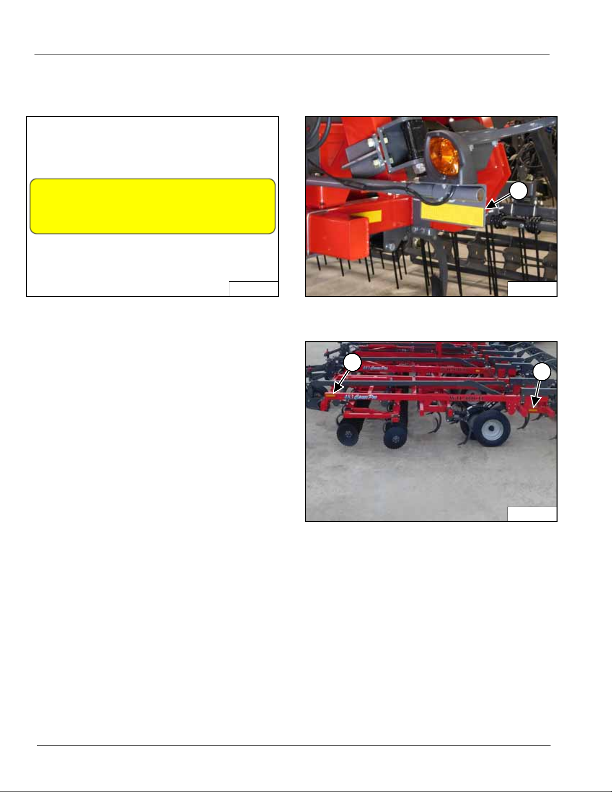
12. Amber Reflector decal - P/N 22372
Front side of all safety lights.
Front and side of both wings.
14 79993 | 08-19
Page 17
SAFETY
WR0184
WR0185
WR0121
WR0124
13
WR0120
14
WR0158
15
Safety Decal Location (Cont’d)
Safety Decals (Cont’d)
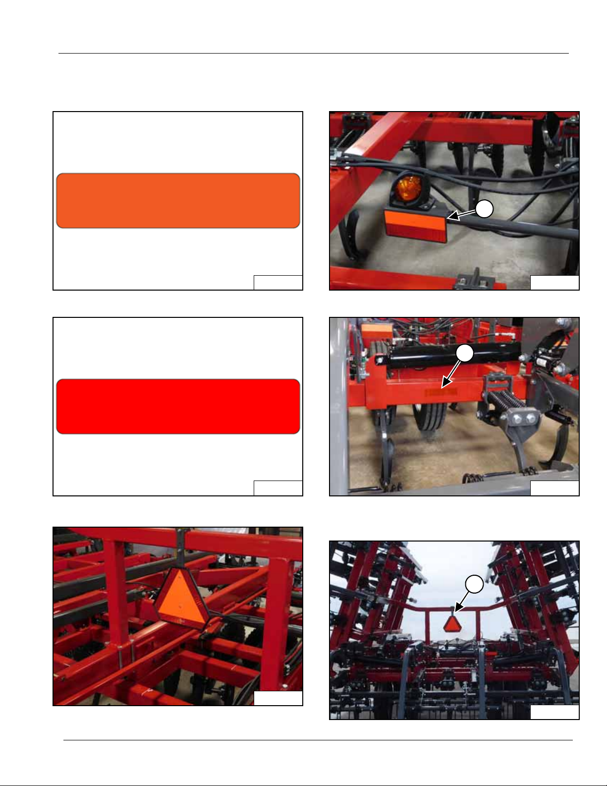
13. Red-Orange Reflector Decal - P/N 223118
14. Red Reflector decal - P/N 22371
Rear side of all safety lights.
Rear outside corner of both LH and RH wings and main
frame.
15. SMV - SLOW MOVING VEHICLE - P/N 41345
79993 | 08-19 15
Center of wing stop bracket.
Page 18
Safety Lighting
WR0135
1
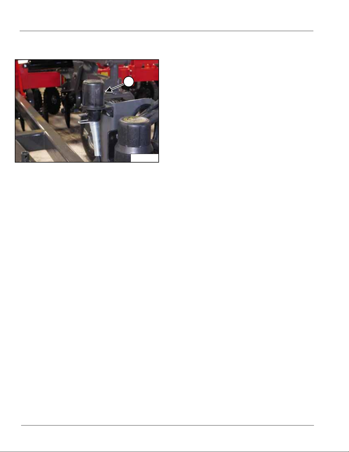
STEP 1
The Safety Light Kit is equipped with a 7-pin connector.
To protect the 7-pin connector, store in dust cap (1)
located on the front of the hitch when not attached to
towing vehicle.
SAFETY
16 79993 | 08-19
Page 19

SAFETY
Operation Safety
• Use extreme care when making adjustments.
• When working under or around the machine always
install transport cylinder locks and lower the machine.
• After servicing, be sure all tools, parts or servicing
equipment is removed from the machine.
• Before and during operation be sure no one is on or
around the implement. Serious injury can result from
improper use.
• Reduce speed when cornering on field ends and
when operating on or across dead furrows.
• Do not attempt to remove any ob struction while the
machine is in motion.
• Use extreme care when operating close to ditches,
fences, or on hillsides.
• No one other than the operator should ride on the
tractor.
General Maintenance Safety Practices
NOTE: Read the entire section before beginning wo rk.
Before you begin
• YOU ARE RESPONSIBLE for the safe maintenance
of the implement.
• DO NOT ALLOW CHILDREN or other unauthorized
persons within the implement operational area.
• WEAR PERSONAL PROTECTIVE EQUPMENT
which includes eye protection, work gloves and steel
toed boots with slip resistant soles.
• DO NOT MODIFY the equipment or substitute parts in
any way. Unauthorized modification may impair the
function and / or safety of the machine.
• USE SUITABLE LIFTING DEVICE for components
which could cause personal injury by pinching,
crushing or weight. BE SURE lifting device is rated to
handle the weight.
• BLOCK UP ANY RAISED PART of the machine. Be
sure machine is stable after blocking.
• ALWAYS INSPECT LIFTING CHAINS AND SLINGS
for damage or wear.
• STOP ENGINE, place all controls in neutral, set
parking brakes, remove ignition key before servicing
or adjusting.
• BE SURE PRESSURE IS RELIEVED from hydraulic
circuits before servicing or disconnecting from tractor.
• USE EXTREME CARE when assembling, servicing
or adjusting.
79993 | 08-19 17
Page 20
SAFETY
WR0190
21
Hydraulic Safety
• Inspect all hydraulic hoses and fittings for cracks and
abrasions at least once a year. Tighten or replace as
needed.
• Do not over-tighten hydraulic fittings, excessive
torque may cause them to crack.
• Care must be taken to prevent twisting when
tightening hose connections. Straighte n any hose that
appears twisted immediately. A twisted hose can
burst under pressure.
• When connecting the hoses to the cylinders, tubings
or fittings; always use one wrench to prevent the hose
from twisting and another wrench to tighten the union.
Excessive twisting will shorten hose life and loosen
hose fittings.
CAUTION: Hydraulic fluid escaping
under pressure can have enough f orce
to penetrate the skin. Hydraulic fluid
may also infect a minor cut or opening
in the skin. If injured by escaping fluid,
see a doctor at once. Serious infection
or reaction can result if medical
treatment is not given immediately.
Make sure all connections are tight and
that hoses and lines are in good
condition before applying pressure to
the system.
Hydraulic Connection Torques
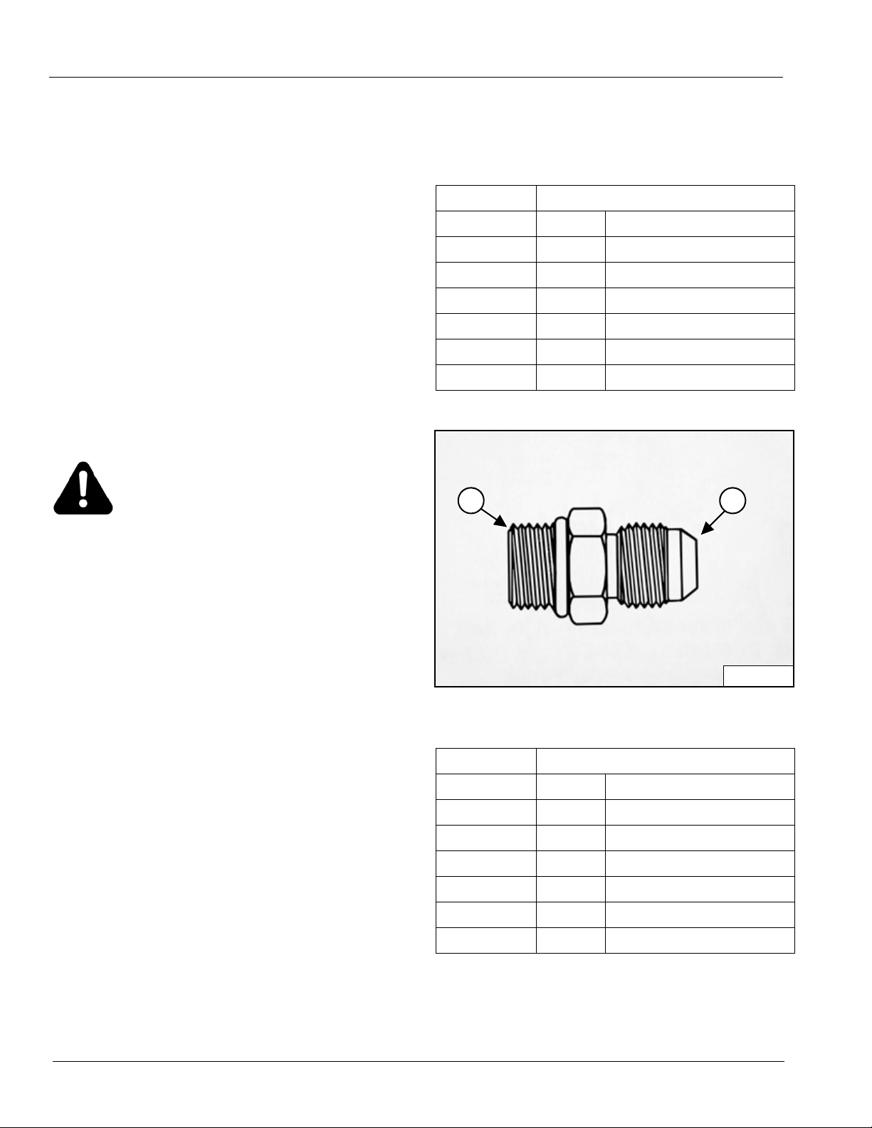
Straight Thread O-ring Boss (ORB) (1)
(example: 12MB - 12MJ is -12 male ORB to -12 male
JIC)
Jam Nut or Straight Fitting Torque
Dash Size Ft / Lbs Newton Meters
-04 13-15 18-20
-05 14-15 19-21
-06 23-24 32-33
-08 40-43 55-57
-10 43-48 59-64
-12 68-75 93-101
To find a leak under pressure, NEVER
USE YOUR HAND, use a small piece of
cardboard or wood.
SAE 37°C (JIC) (2)
(example: 8FJ - 8FJ is -08 female JIC)
Jam Nut or Straight Fitting Torque
Dash Size Ft / Lbs Newton Meters
-04 11-12 15-16
-05 15-16 20-22
-06 18-20 24-28
-08 38-42 52-58
-10 57-62 77-85
-12 79-87 108-119
IMPORTANT: SAE 37° fittings can be damaged if over
torqued.
18 79993 | 08-19
Page 21

SAFETY
Transporting Safety
• Always place the machine in the transport position
with the wing folded up.
• Install transport cylinder locks (See page 25).
• Comply with your state and local laws governing
highway safety when moving machinery on a
highway.
• Reduce road speed on corners.
• Drive at a reasonable speed to maintain complete
control of the machine at all times. Maximum
transport speed is 20 mph.
• A S.M.V. emblem must be used at all times while
traveling on public roads.
• Be sure the safety lights are working.
• Obey all local, state and federal lighting requireme nts.
79993 | 08-19 19
Page 22

SAFETY
20 79993 | 08-19
Page 23
PREPARATION
SM00013
SAE
Grade 5
SAE
Grade 8
Before using the implement a careful inspection must
become routine.
Check to be sure that all hardware is securely tightened
and moving parts properly lubricated.
• Tighten all loose nuts and bolts and replace any bent
or broken parts.
• When tightening bolts, they must be torqued to the
proper number of foot-pounds as indicated in the
table unless specified. It is important that all bolts be
kept tight.
• On new machines, all nuts and bolts must be
rechecked after a few hours of operation.
• When replacing a bolt, use only a bolt of the same
grade or higher. Except in shear bolt applications,
where you must use the same grade bolt.
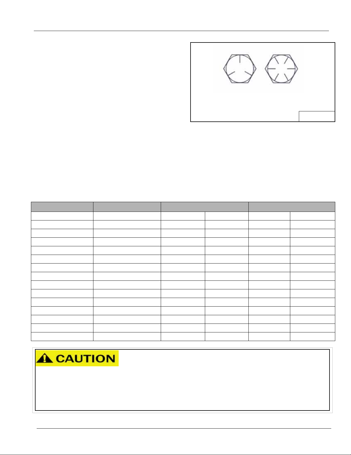
• Bolts with no marking are grade 2.
• Grade 5 bolts furnished with the machine are
identified by three radial lines on the head.
• Grade 8 bolts furnished with the machine are
identified by six radial lines on the head.
• All U-bolts are grade 5.
BOLT SIZE WRENCH SIZE GRADE 5 GRADE 8
lb-ft N•m lb-ft N•m
1/4 in. 7/16 in. or 3/8 in. 7 9.5 12 17
5/16 in. 1/2 in. 15 20 25 34
3/8 in. 9/16 in. 30 41 45 61
7/16 in. 5/8 in. or 11/16 in. 45 61 70 95
1/2 in. 3/4 in. 70 95 105 142
9/16 in. wheel bolts 7/8 in. 170 231 - -
5/8 in. 15/16 in. 170 231 210 285
5/8 in. wheel nuts 1-1/16 in. 240 325 - -
3/4 in. 1-1/16 in.* or 1-1/8 in.* 250 339 375 509
7/8 in. 1-5/16 in. 350 475 600 814
1 in. 1-1/2 in. 450 610 880 1193
1-1/4 in. 1-7/8 in. 500 678 - 1-1/2 in. 2-3/4 in. 570 773 - -
2 in. 3-1/8 in. 1200 1627 - -
• Just before and during
operation be sure no one is
FAILURE TO FOLLOW THESE
INSTRUCTIONS MAY RESULT
IN PERSONAL INJURY AND/OR
EQUIPMENT DAMAGE.
79993 | 08-19 21
on or around the implement.
• Before activating the hydraulic
system, check hoses for proper
connections.
• Before lowering the wings for the
first time, make sure the entire
system has been charged with oil.
Page 24
PREPARATION
WR0174
WR0044
1
WR0131
1
WR0132
1
Hydraulics
STEP 1
On all new machines check the hydraulic system to be
sure all fittings are tight.
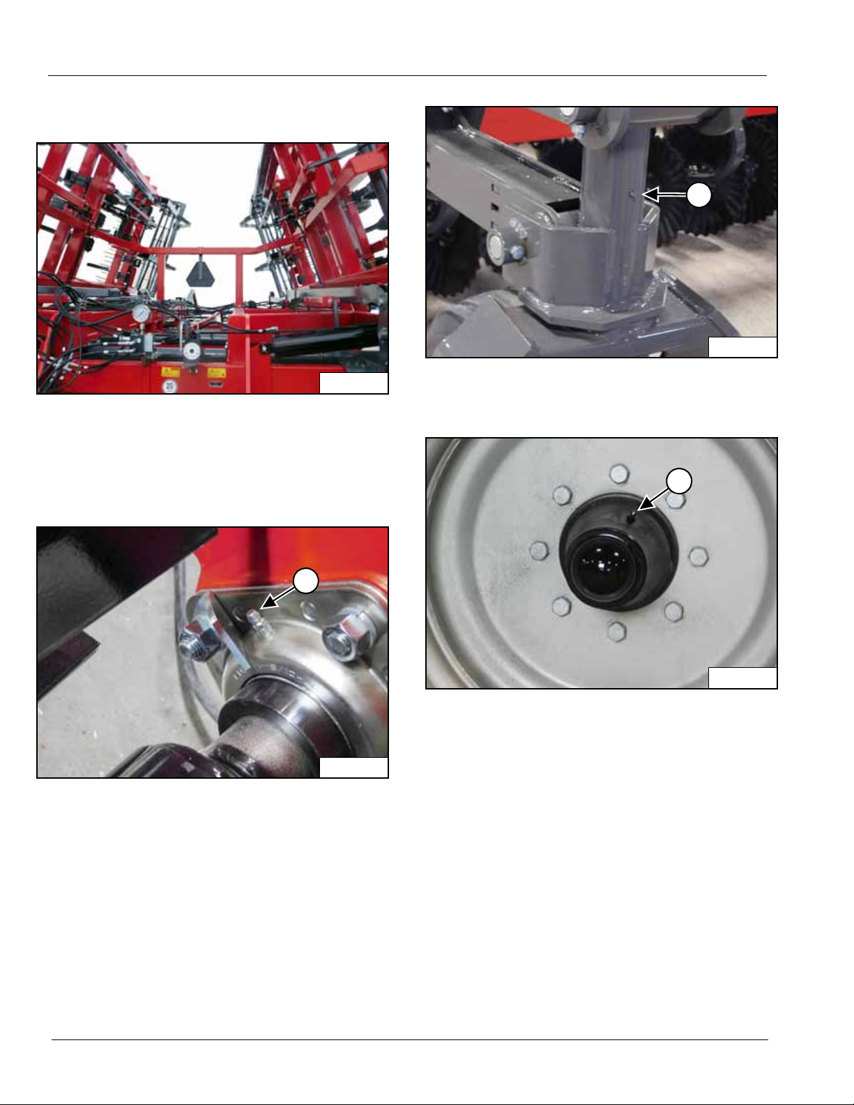
Lubrication
STEP 2
Grease the four front lift wheel pivot spindles (1).
STEP 3
STEP 1
Grease the eight bearings (1) on the rear flat bar roller.
Grease all the lift wheel hubs (1).
22 79993 | 08-19
Page 25
PREPARATION
WR0129
1
WR0186
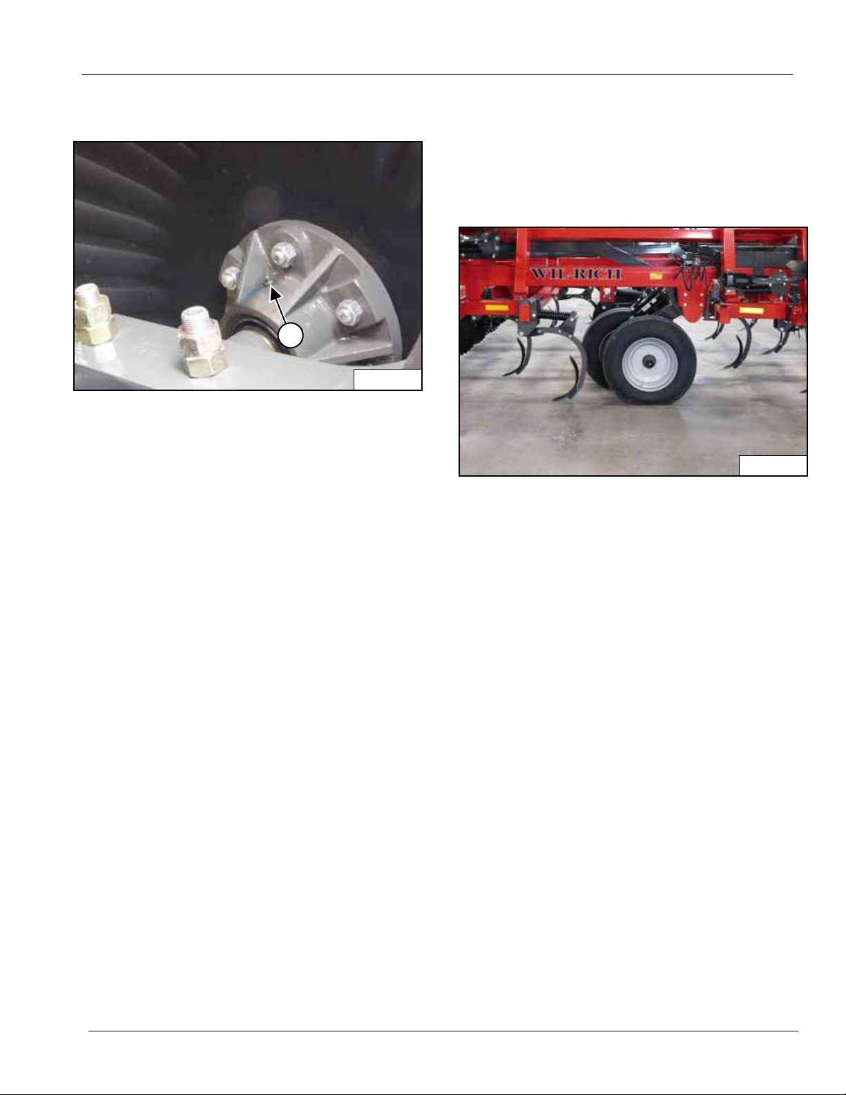
Lubrication (Cont’d)
STEP 4
Grease each disk hub (1).
Tractor Preparation
Refer to the operator’s manual furnished with your tractor
for recommended adjustme nts and weight distribution.
Wheels
STEP 1
The use of the proper air pressure is the most important
factor in satisfactory performance and maintenance of
implement tires. Underinflation will damage the cord body
of the tire and cause a series of diagonal breaks in the
fabric in the sidew all area.
If the tire buckles or wrinkles, the air pressure must be
increased to the point where the sidew alls remain smooth
while operating.
NOTE: DO NOT OVERINFLATE TIRES.
Check the air pressure every two or three weeks and do
not allow pressure to drop to a point where buckling or
wrinkling of the tire may be possible.
The recommended tire pressure for each front gauge
wheel is 55 psi (3.7 bar) and the rear lift wheels is 70 psi
(4.8 bar).
It is recommended that all wheel nuts be checked for
tightness after first day of use. Wheel nuts are tightened
to 90 ft-lbs (122 N•m). Check periodically to be sure the
wheel nuts are tight. Paint or rust can work out causing
the wheel to become loose.
79993 | 08-19 23
Page 26

PREPARATION
24 79993 | 08-19
Page 27
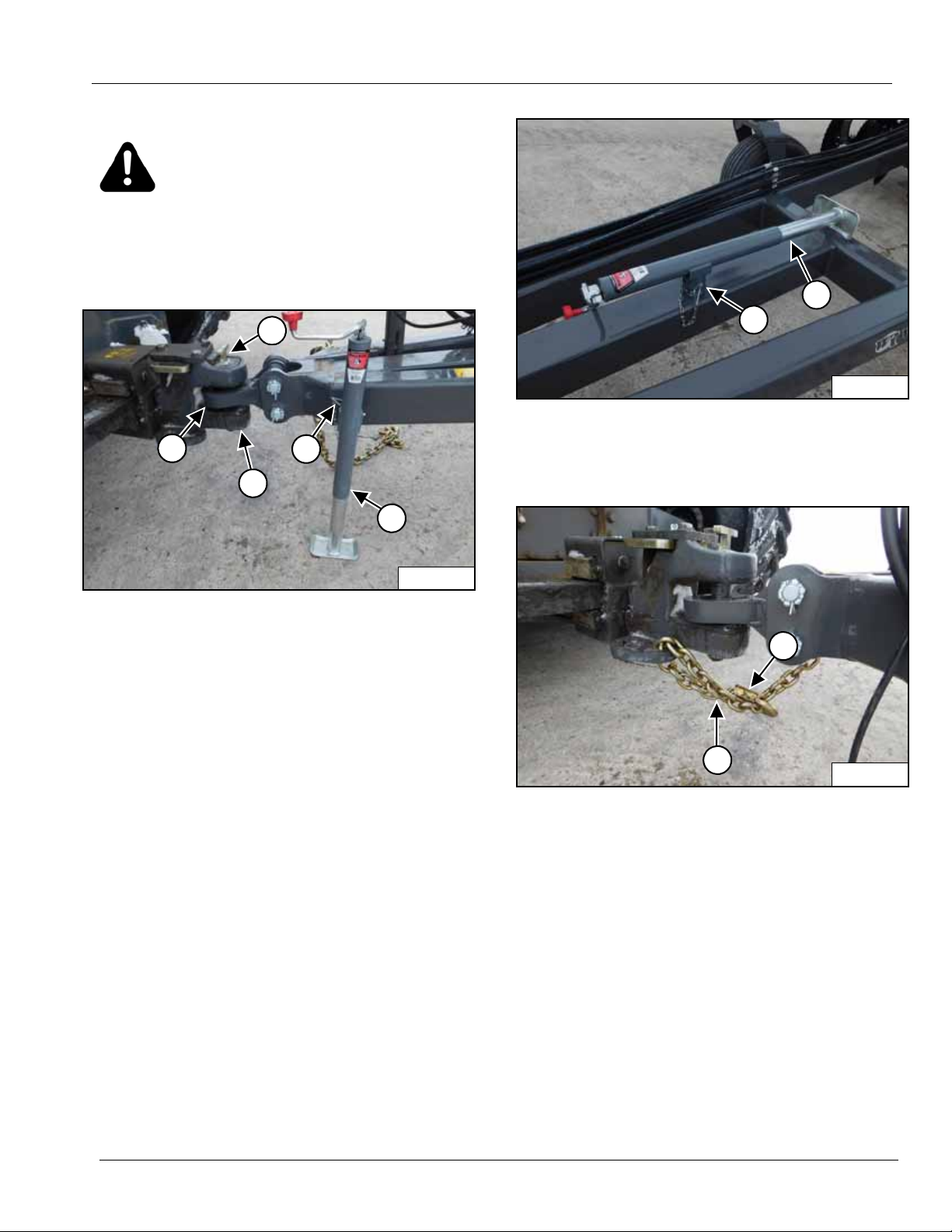
CONNECTING THE IMPLEMENT
WR0150
3
4
1
2
5
WR0148
2
1
WR0147
1
2
WARNING: Never allow anyone between
the tractor and implement when
connecting or disconnecting the
implement until the implement is
completely supported on the 3-point
hitch, the engine is stopped and the park
brake is applied.
STEP 1
STEP 2
Install the jack (1) in the storage position on the drawbar
as shown. Secure with the pin (2).
STEP 3
Use the jack (1) to align the implement tongue (2) with
the tractor drawbar (3). Slowly back the tractor onto the
tongue (2) and install the pin (4).
IMPORTANT: Be sure the pin mechanical lock device
is in place. The device may be a pin lock plate as
shown or a cross pin on the drop pin.
Retract the jack until the implement tongue and hitch are
supported by the tractor. Remove the pin (5) and remove
the jack.
Install the safety chain (1) as shown.
IMPORTANT: Be sure the safety chain lock (2) is
secured.
79993 | 08-19 25
Page 28
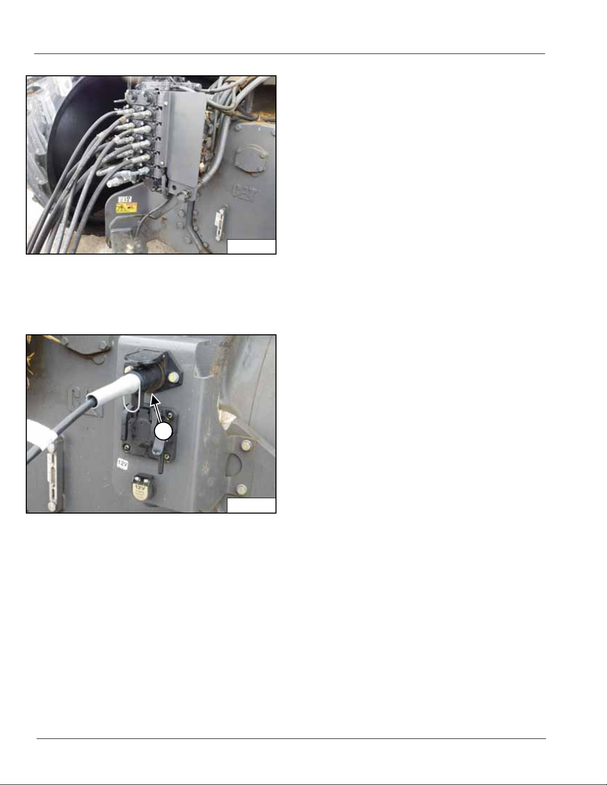
STEP 4
WR0164
WR0163
1
Install the wing lift, shank lift, wheel lift and rolling basket
cylinder hoses on the tractor. Be sure the hose couplers
are secured in the tractor couplers.
STEP 5
CONNECTING THE IMPLEMENT
Install the safety light connector (1) on the tractor.
26 79993 | 08-19
Page 29
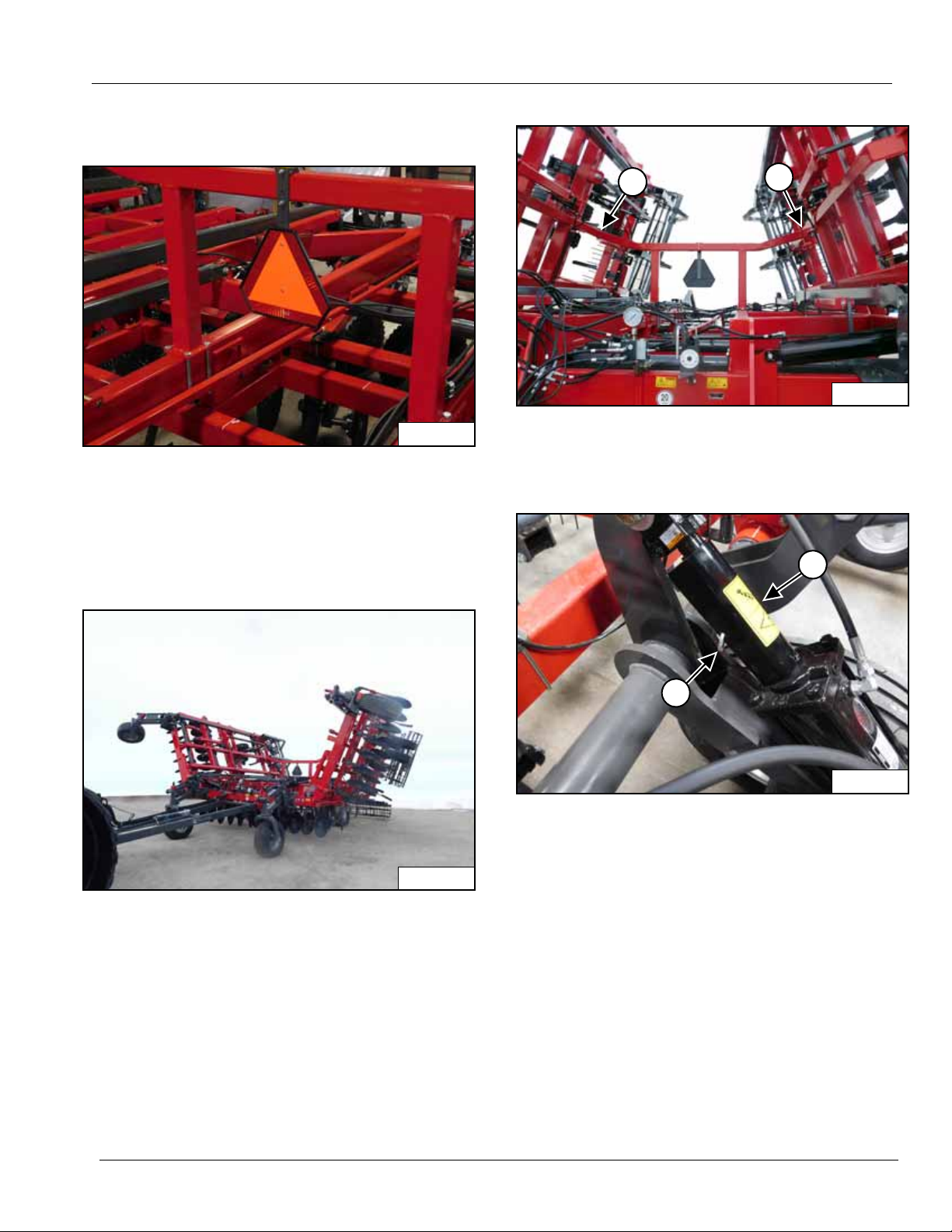
OPERATION
WR0121
WR0166
WR0174
1
1
WR0113
1
2
Transporting
STEP 1
A Slow Moving Vehicle (S.M.V.) emblem must be used at
all times while traveling on public roads.
Be sure all safety lights are working. Obey all local, state
and federal laws for lighting requirements.
STEP 3
Be sure the wings are resting securely on the wing
supports (1).
STEP 4
STEP 2
ALWAYS fold the wings up before transporting.
IMPORTA NT: If the implement h as b een sto red o r out
of operation for months or if hydraulic wing cylinders
have recently been replaced perform the following
procedure.
Raise the implement. Shut off the engine, apply the park
brake and remove the key from the tractor. Install the
cylinder locks (1) on both main frame wheel lift cylinders.
Install the pins (2) in the cylinder locks (1).
Start the engine and lower the main frame onto the
cylinder locks (1).
Fold and unfold the wings several times and hold the
hydraulic lever in the extended position for 30
seconds each time to purge air from the system.
79993 | 08-19 27
Page 30
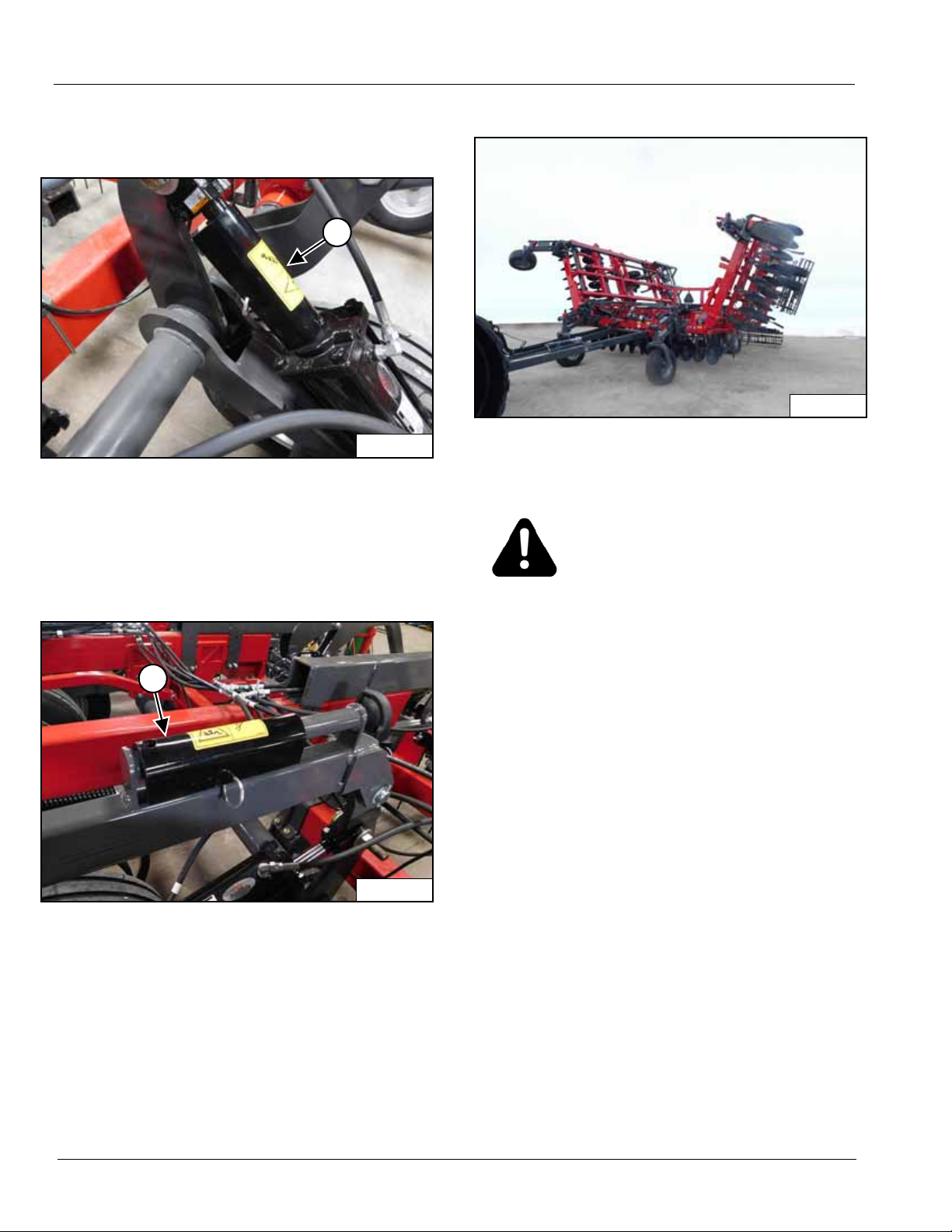
OPERATION
WR0113
1
WR0111
1
WR0166
Field Operation Preparation
STEP 1
Park the tracto r on level ground.
Raise the main frame to maximum height. Shut off the
engine and remove the key from the tractor. Remove the
cylinder locks (1) from the main frame wheel lift cylinders.
STEP 3
Start the tractor and un fold the wings.
DANGER: Be sure all personnel are
cleared from the area of implement
operation.
STEP 2
Install the cylinder locks (1) in the storage position.
28 79993 | 08-19
Page 31
OPERATION
WR0171
1
2
WR0127
1
1
2
3
WR0133
1
2
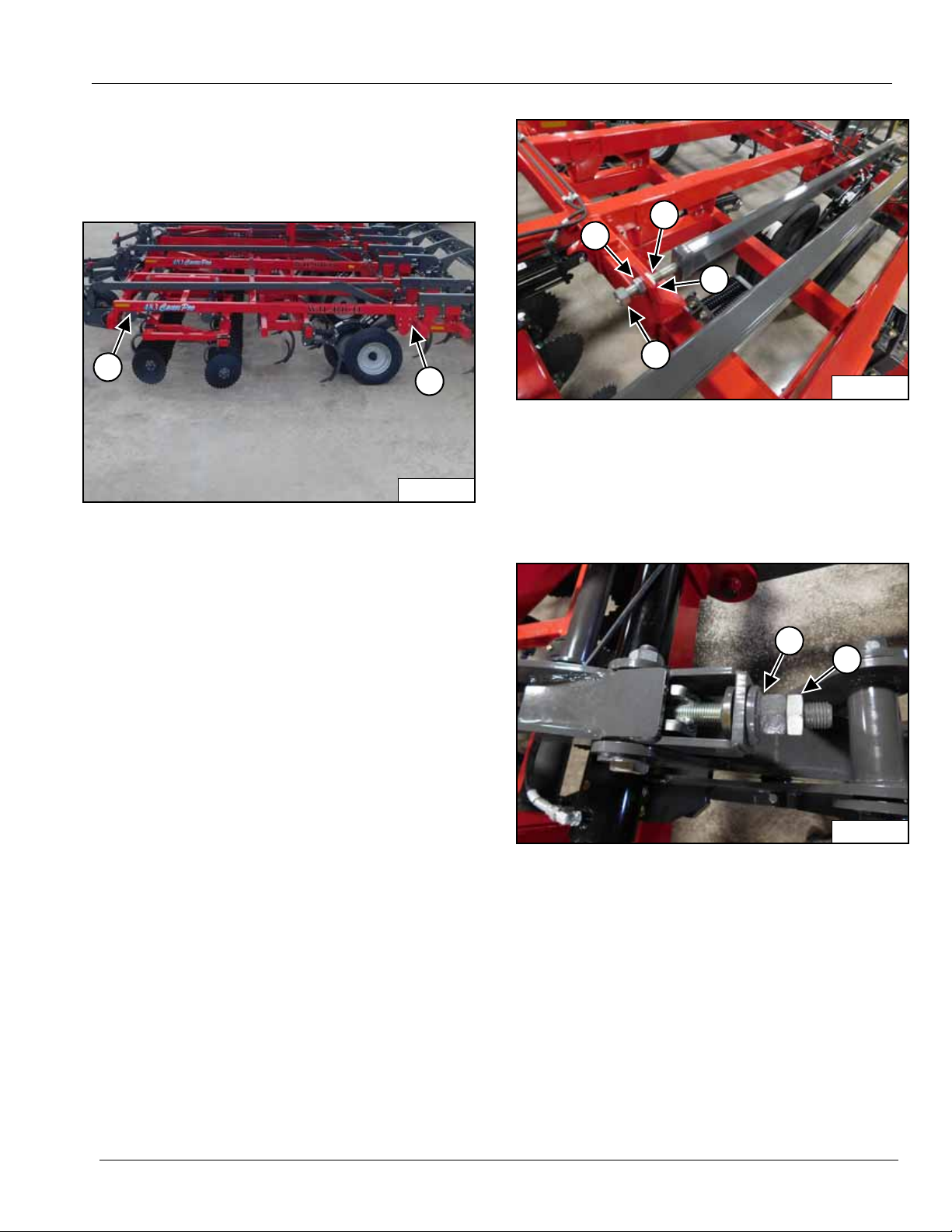
Field Operation Leveling Adjustments
The 483 Chisel Pro is leveled at delivery but leveling may
be necessary due to soil conditions or extended use.
STEP 1
Raise and lower the lift wheels a number of times and
hold the hydraulic lever in the RAISE position each time
for 30 seconds to purge any air in the system.
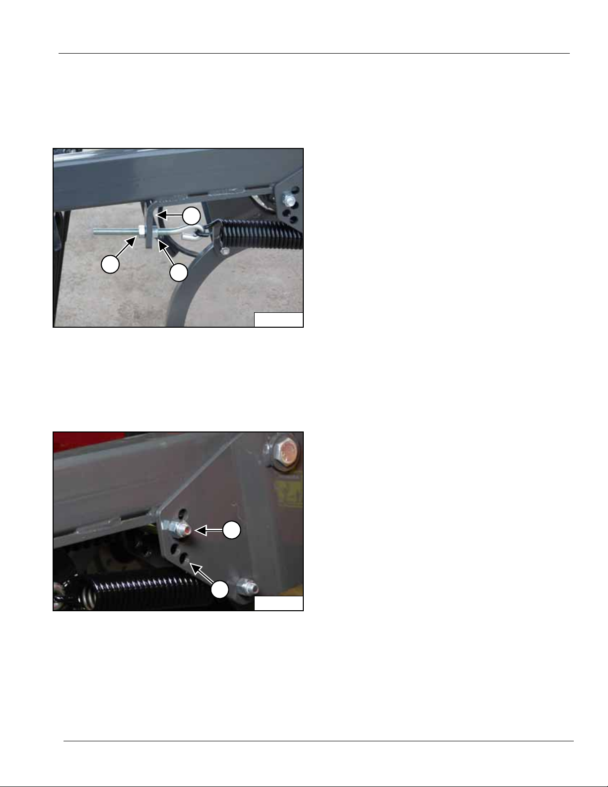
STEP 2
To change the height of the rear lift wheels, loosen the
jam nuts (1) and lengthen the adjusting bo lt (2) to lower
the frame and shorten the adjusting bolt (2) to raise the
frame. Tighten the jam nuts (1) against the frame bracket
(3).
STEP 3
NOTE: Be sure the tractor and implement are parked
on a level surface.
Lower the implement until the disks and chisels are about
1 inch (25 mm) above the ground. Take measurements
from the top of the frame to the ground at the front (1)
and rear (2) of each frame sec tion. The measurements
must be the same for the implement to operate lev el.
To change the height of the front lift wheels loosen the
jam nut (1) and turn the adjusting nut (2) clockwise to
raise the frame and counterclockwise to lower the frame.
79993 | 08-19 29
Page 32
OPERATION
WR0170
WR0182
WR0109
1
WR0110
2
1
Field Operation Leveling Adjustments
(Cont’d)
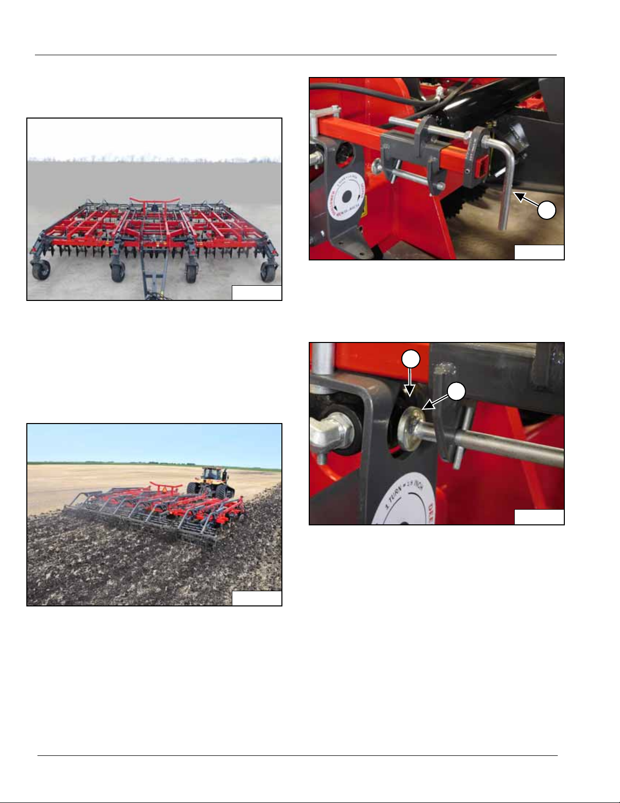
STEP 4
Repeat Steps 2 and 3 until all frame sections are level
front to rear and the wings are level with the main frame.
STEP 2
Stop the tractor and check the soil penetration depth.
Use the shank depth control adjuster (1) to fine tune the
depth setting.
STEP 3
Field Operation Settings
Shank Depth Setting
STEP 1
In the field lower the implement to the ground and run a
test strip. Use the lift wheels to change soil penetration
depth until desired depth is achie ved.
Tur n the shank depth con trol adjuster clockwise until the
adjuster stop (1) contacts the lift wheel depth control
valve (2). Turning the depth control adjuster clockwise will
increase depth and counterclockwise will decrease the
depth of the implement. The depth can be fine tuned 1/8
inch (3.2 mm) with one full turn of the adjuster handle.
Run a test strip and check the setting. Repeat this step
until correct depth is achieved.
30 79993 | 08-19
Page 33
OPERATION
WR0100
1
WR0102
1
WR0169
1
WR0105
1
Field Operation Settings (Cont’d)
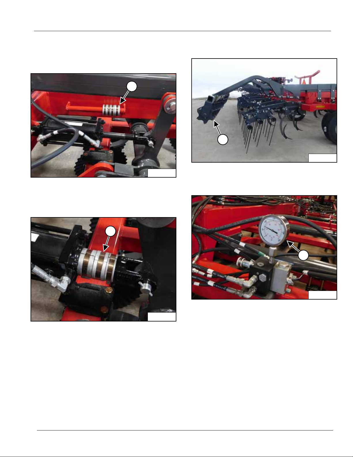
Disk Depth Setting
STEP 1
The disk depth can be set with the cylinder stops (1)
located by the disk lift cylinders.
Flat Bar Rolling Basket Setting
STEP 1
Lower the rolling baskets (1) to the ground.
STEP 2
STEP 2
Install one to four cylinder stops (1) on the main frame
disk lift cylinders. Each stop will restrict the depth of
penetration of the disks.
NOTE: The cylinder stops (1) must only be used on
the main frame disk lift cylinders.
Hold the hydraulic lever in the down position and re ad the
rolling basket system pressure gauge (1).
79993 | 08-19 31
Page 34
OPERATION
WR0107
1
2
WR0104
1
2
Field Operation Settings (Cont’d)
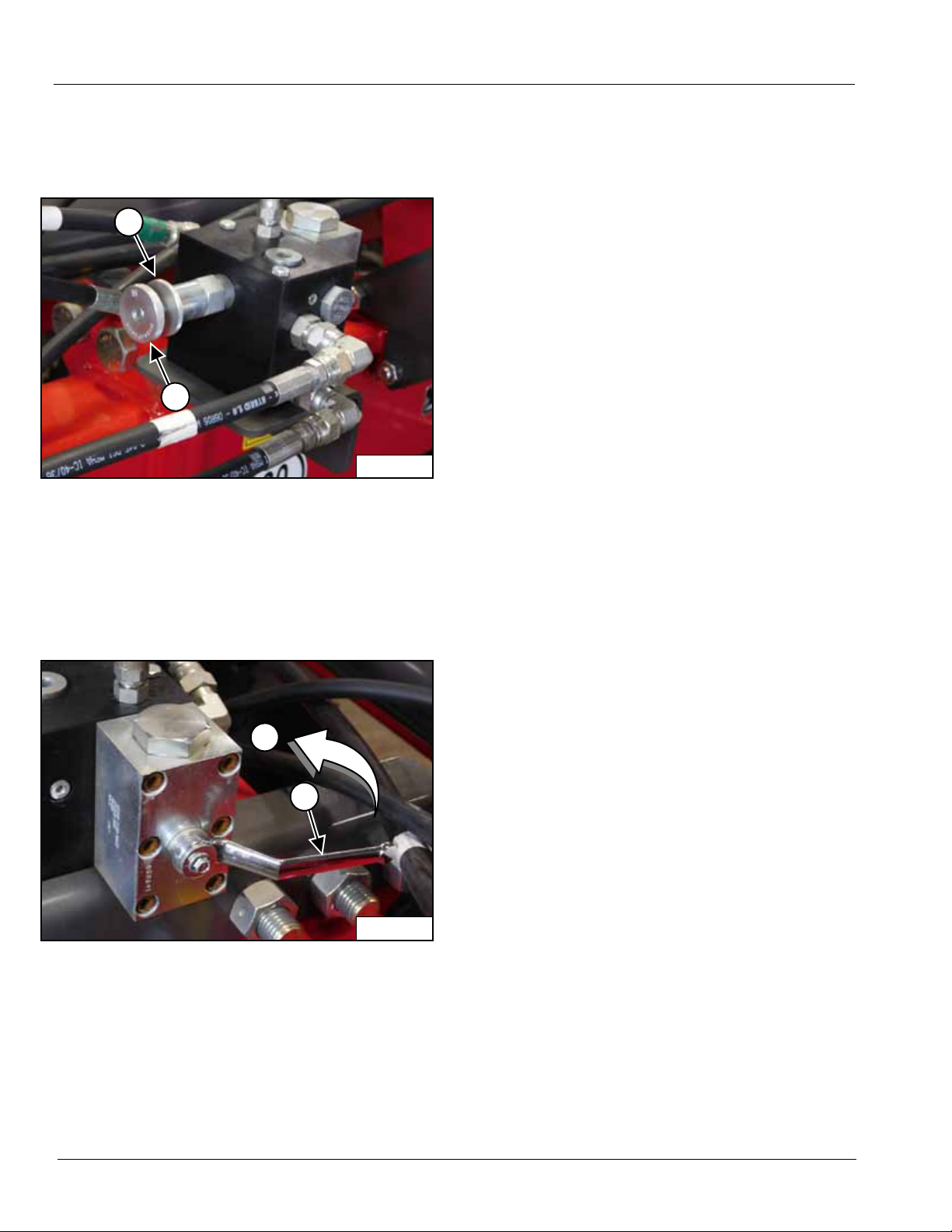
Flat Bar Rolling Basket Setting (Cont’d)
STEP 3
To change the down pressure on the baskets, loosen the
lock disk (1) and turn the control knob (2) clockwise to
increase and counterclockwise to decrease the down
pressure.
NOTE: The down pressure is factory set at 1000 psi.
STEP 4
Hydraulic Basket Operation
With the hydraulic rolling basket, there are several
adjustments to achieve the best residue management.
Depending on field conditions, adjustments can be made
to create an even, level surface finish.
Dry Conditions - During dry f ield conditions, the active
down pressure can be used. The factory setting is at
1000 psi. If more basket crumbling action and residue
pinning is required, increase the down pressure app lied
to the baskets (raise gauge pressure). Be care ful not to
set the pressure too high, or the basket will lift the coil
tines harrows and rear chisels out of the ground.
Normal Field Conditions - During normal field
conditions the active down pressure can be used. The
factory setting (1000 psi) is a good place to start.
Depending on residue and soil surface finish, pressure
can either be lowered or raised to achieve optimal soil
finish. If less soil crumbling and residue pinning is desired
the psi can be reduced.
Wet Field Conditions - During wet field conditions the
float condition may be used. This operation may be
useful when the basket begins to acquire soil. Float will
allow basket to lightly float over the soil while still pinning
residue and breaking up soil clumps without acquiring
soil on the baskets. If the baskets begin to acquire too
much soil, they can be raised to just allow the coil tine
harrow to level the soil and residue.
To put the baskets in FLOAT mode move the control va lv e
lever ( 1) f rom t he h orizo nt al positi on shown to the vertical
(2) position. In FLOAT mode the only down pressure is
the weight of the basket assemblies.
32 79993 | 08-19
Page 35
OPERATION
WR0177
1
2
1
WR0139
1
2
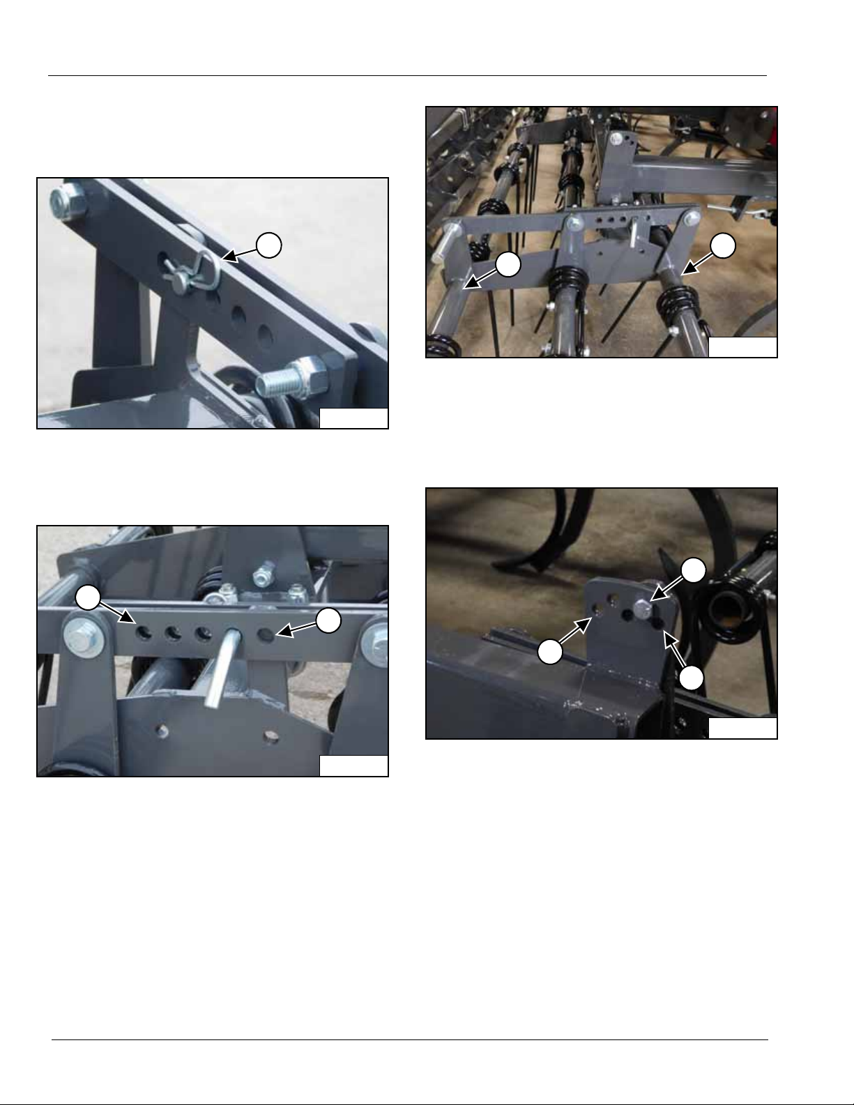
Coil Tine Harrow Settings
The harrows are set at Wil-Rich but due to soil conditions
or wear of the coil tines they may need to be adjusted for
the desired effect.
STEP 1
To increase or decrease the down pressure on the tines
loosen the jam nuts (1). Turn both nuts (1) clockwise to
increase down pressure or counterclockwise to decrease
down pressure. Tighten the two jam nuts (1) on the
bracket (2).
STEP 2
The maximum depth of the harrow assemb ly is controlled
by the position of the stop bolt (1) in the harrow arm
bracket. The lower the position (2) of the bolt (1) the
deeper the harrow penetration.
79993 | 08-19 33
Page 36
OPERATION
WR0179
1
WR0178
1
2
WR0117
1
2
WR0115
1
2
3
Field Operation Settings (Cont’d)
Harrow Settings (Cont’d)
STEP 3
To change the pitch of the harrow tines remove the
retaining pin (1).
STEP 5
The front (1) to back (2) leveling of the harrow assembly
can be changed to keep the harrow level when the depth
of the disks and shanks are changed or to change the
penetration from the front to the rear tines.
STEP 6
STEP 4
Remove the pi n. Mo v e the pin forward (1) to decrease the
pitch and back (2) to increase. Install the retaining pin
from Step 3.
NOTE: The more vertical the pitch of the tines the
more aggressively the harrow will penetrate
the soil. The increased pitch will allow more
debris to pass through the harrow.
Remove the bolts ( 1), lock nuts and washers. Position the
harrow assembly arm forward (2) for shallow disk / shank
settings and rearward (3) for deeper settings. Install the
bolt, washer and lock nut (1) when set.
IMPORTANT: The same setting must be used on all
harrow sections.
34 79993 | 08-19
Page 37
MAINTENANCE
WR0174
WR0090
WR0180
1
2
WR0169
1
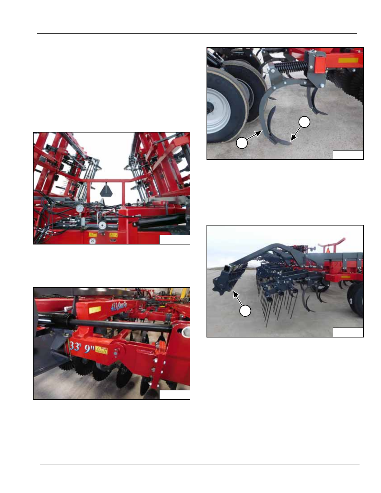
Daily
STEP 1
Inspect all bolts and fastene rs for tightness and damage.
Replace any damaged fasteners immediately.
IMPORTANT: Loose bolts or fasteners can result in
damage to the implement.
STEP 2
STEP 4
Check the shanks (1) for excessive wear, damage or
broken parts on shovels (2).
NOTE: A bent or worn shank can effect the efficiency
of the Chisel Pro.
STEP 5
Check hydraulic hoses and fittings for leaks or damage.
Tighten or replace immediately.
STEP 3
Check the wing hinges for excessive wear, damaged or
bent parts or links.
Check the rolling basket (1) for excessive wear or
damage.
79993 | 08-19 35
Page 38
MAINTENANCE
WR0130
1
WR0044
1
WR0132
1
2
WR0157
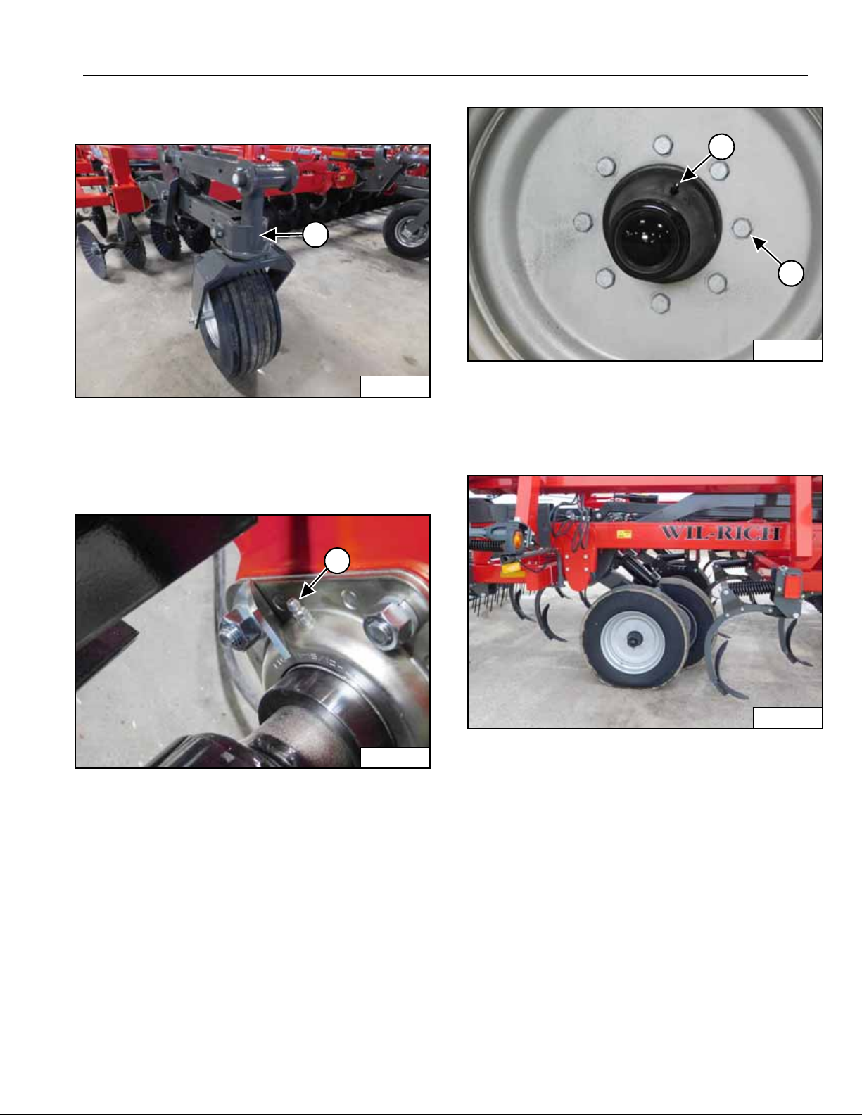
Daily (Cont’d)
STEP 6
Lubricate the pivots (1) on the front gauge wheels.
50 Hours
STEP 1
STEP 2
Lubricate the wheel hubs (1). Check the wheel lug bolts
(2) for correct torque. Tighten lug bolts (2) to 90 ft-lbs
(122 N•m).
STEP 3
After the initial pre-operation lubrication, the rear rolling
baskets (1) must be lubricated with clean multipurpose
heavy duty lithium grease every 50 hours of operation.
Check the air pressure in all tires. The front gauge
wheels must be at 55 psi (3.7 bar). The rear main frame
lift wheels must be at 70 psi (4.8 bar).
36 79993 | 08-19
Page 39
MAINTENANCE
WR0170
50 Hours (Cont’d)
STEP 4
Clean dirt, debris or grease from all moving parts.
1000 Hours Or Yearly
STEP 1
Remove all dirt and debris from the implement that could
hold moisture and cause rusting.
STEP 2
Repaint any chipped areas or clean and paint rusted
areas.
STEP 3
Inspect the machine for any worn or damaged parts and
replace immediately.
STEP 4
Grease the rolling basket bearings as in the 50 hours
maintenance.
79993 | 08-19 37
Page 40

MAINTENANCE
Storage
Preparing The Machine For Storage
Prepare the machine for storage at the end of each
season. When possible, store the machine in a covered
location with the wings lowered. Preventing rust will
lengthen the life and assist in performance.
Procedure
1. Park the implement on a solid, level surface, away
from other machines.
2. Use the tractor hydraulics to lower the wings of the
implement.
3. Clean the implement of any dirt, grease or other
materials.
4. Put a protective layer of heavy oil or grease on all
earth engaging parts to prevent rust.
5. Paint any damaged surfaces, surfaces with paint
removed, or surfaces with rust.
6. Inspect the implement for any loose parts or
hardware.
a) Replace any worn parts.
b) Tighten any loose hardware.
7. Lubricate all components of the implement.
8. Raise the implement and transport to the area where
it is to be kept. The area must be level.
9. Stop the engine, apply the park brake, and take the
key with you.
10. Place boards under the disks and shanks.
IMPORTANT: If boards cannot be placed under
the disks and shanks, place the cylinde r stops on
the main frame lift cylinders. Lower the i mplement
onto the cylinder stops. This will prevent the
disks and shanks from penetrating the ground.
11. Start the engine and lower the implement on the
boards under the shanks.
12. Completely retract the wheel lift cylinders.
13. Use the front hitch jack to support the front hitch of the
implement.
14. Remove the tractor from the implement.
15. Apply grease to the surfaces of the cylinder rods that
are still showing.
38 79993 | 08-19
Page 41

TROUBLESHOOTING
Troubleshooting Chart
PROBLEM POSSIBLE CAUSE SOLUTION
Lift cylinders are not in phase. There is air in the system. Bleed the system by extending the cylinders and
hold the hydraulic lever for 1 to 5 minutes.
Wings are lowering with
hydraulic lever in neutral.
Wheel lift cylinders are
allowing the implement to
lower.
The implement is not pulling
evenly .
The depth is not even.
Wings are bouncing. The implement is operating too
Hydraulic fluid is flowing past the
cylinder pistons.
Hydraulic fluid is flowing past the
lift cylinder pistons.
Depth is not even. Level the wings and center frame.
Shanks or disks are worn or
broken.
The implement is not level when
under power.
fast.
The outside edge of the wings is
too deep.
Install new seals in the cylinder or replace the
cylinder.
Install new seals in the cylinders or replace the
cylinders.
Replace worn or damaged shanks or disks.
Level the implement front to rear and the wings with
the center frame.
Reduce speed.
Level the wings with the center frame.
79993 | 08-19 39
Page 42

TROUBLESHOOTING
40 79993 | 08-19
Page 43

Page 44

wil-rich.com
Wil-Rich © 2019
 Loading...