

WIL-RICH 10K Assembly & Operators Manual
ASSEMBLY/OPERAT OR’S
1
MANUAL
10K FOLDING TOOLBAR
STRIP TILL
Printed in USA (74283) 8/18
WIL-RICH
PO Box 1030
Wahpeton, ND 58074
PH (701) 642-2621
Fax (701) 642-3372
www .wil-rich.com

AGCO-Amity JV LLC LIMITED WARRANTY TERMS AND CONDITIONS – UNITED STATES AND CANADA
2
EFFECTIVE FOR EQUIPMENT RETAILED AND DELIVERED AFTER JANUARY 1, 2018
WHAT IS WARRANTED AGCO Amity JV warrants its new equipment to be free of defects in material and workmanship at time of delivery to the first retail
purchaser, renter, or lessee. These terms apply to all Wishek, Wil-Rich, and Amity brands of new equipment originally marke ted in the United States and
Canada.
WARRANTY PERIOD
• 12 Months from the date of delivery to the first retail purchaser, renter or lessee.
• Field Cultivator and Disk Cultivators: 3 years on main frames, wing frames, and shank assemblies
• Precision Shank Drill: 3 years on main frame, wing frame, and rockshafts.
EXCEPTIONS FROM THIS WARRANTY
• Freight Charges - This warranty does not cover freight charges.
• Improvements, Changes, or Discontinuance AGCO Am ity JV reserve s the right to make changes and improvements in design or changes in
specifications at any time to any product without incurring any obligations to owners of products previou sly sold.
• Repairs and Maintenance Not Covered Under Warranty - This warranty does not cover conditions resulting from misuse, natural calamities,
use of non-AGCO-Amity JV parts, negligence, alteration, accident, use of unapproved attachments, usage which is contrary to the intended
purposes, or conditions caused by failure to perform required maintenance. Replacement of Wear or Maintenance items (unless defective) such
as but not limited to, filters, hoses, belts, lubricants, light bulbs, wheel alignment, tightening of nuts, belts, bolts, and fittings, service tune-up,
computer parameter adjustments and general adjustments which may from time to time be required are not covered.
• Rubber Tire Warranty - Rubber tires are warranted directly by the respectiv e manufacturer only and not by AGCO Amity JV.
• Satellite Outages - Interruptions in satellite interfaces and satellite communications are outside the control of this product and are not covered by
this warranty. The company is not responsible for issues or degradation of system performance resulting from such interruptions in satellite
interfaces and satellite communications where the issues are not related to defect s in this product.
OWNER’S OBLIGATION
It is the responsibility of the Owner to transport the equipment or parts to the service shop of an authorized AGCO Amity JV Dealer or alternatively to
reimburse the Dealer for any travel or transportation expense involved in fulfilling this warranty. This Warranty does NOT cover rental of replacement
equipment during the repair period, damage to products which have been declared a total loss and subsequently salvaged, overtime labor charges, freight
charges for replacement parts, or special handling requirements (such as, but not limited to, the use of cranes).
EXCLUSIVE EFFECT OF WARRANTY AND LIMITATION OF LIABILITY
THIS WARRANTY IS IN LIEU OF ALL WARRANTIES OF MERCHANTABILITY, FITNESS FOR A PURPOSE OR OTHER REPRESENTATIONS, WARRANTIES
OR CONDITIONS, EXPRESSED OR IMPLIED. The remedies of the Owner set forth herein are exclusive. The Company neither assumes nor authorizes any
person to assume for it any other obligation or liability in connection with the sale of covered machines. Correction of defects, in the manner and for applicable
period of time provided above, shall constitute fulfillment of all responsibilities of AGCO Amity JV to the Owner, and AGCO Amity JV shall not be liable for
negligence under contract or in any manner with respect to such machines. IN NO EVENT SHALL THE OWNER BE ENTITLED TO RECOVER FOR INCIDENTAL,
SPECIAL OR CONSEQUENTIAL DAMAGES SUCH AS BUT NOT LIMITED TO, LOSS OF CROPS, LOSS OF PROFITS OR REVENUE, OTHER COMMERCIAL
LOSSES, INCONVENIENCE OR COST OF RENTAL OR REPLACEMENT EQUIPMENT.
Some States or Provinces do not permit limitations or exclusions of implied warranties or incidental or consequential damages, so the limitations or exclusions in this warranty may
not apply.
“AGCO Amity JV” AS REFERRED TO HEREIN WITH RESPECT TO SALES IN: UNITED STATES and CANADA: AGCO Amity JV LLC
PO Box 1030
Wahpeton, ND 58074
Additional Warranty Information
New Equipment Warranty - Equipment is eligible for warranty service only if it qualifies under the provisions of the New Equipment Warranty. The selling
dealer will deliver this Warranty to the original retail purchaser at the time of sale, and the dealer will register the sale and Warranty with AGCO Amity JV
LLC.
Subsequent Owners - This Warranty covers the first retail purchaser and all subsequent owners of the equipment during the specified warranty period.
Should the AGCO Amity JV Dealer sell this equipment to a subsequent owner, the Dealer must deliver the warranty document to the subsequent owner so the
subsequent owner can register ownership with AGCO Amity JV and obtain the remaining warranty benefits, if available, with no intermission in the Warranty
Period. Subsequent Owner Procedure will apply. It is the responsibility of the subsequent owner to transport the equipment to the service shop of an
authorized AGCO Amity JV Dealer or alternatively to reimburse the Dealer for any travel or transportation expense involved in fulfilling this warranty. This
Warranty does NOT cover charges for rental or replacement equipment during the repair period, products which have been declared a total loss and
subsequently salvaged, overtime labor charges, freight charges for replacement parts, or units sold at auction.
Warranty Service - To be covered by Warranty, service must be performed by an authorized AGCO Amity JV Dealer. It is recommended that you obtain
warranty service from the Dealer who sold you the equipment because of that Dealer’s continued interest in you as a valued customer. In the event this is
not possible, warranty service may be performed by any other authorized AGCO Amity JV Dealers in the United States or Canada. It is the responsibility
of the Owner to transport the equipment to the service shop of an authorized AGCO Amity JV Dealer or alternatively to reimburse the Dealer for any travel or
transportation expense involved in fulfilling this warranty.
Maintenance Service - The Owner’s Manual furnished to you with the equipment at the time of delivery contains important maintenance and service
information. You must read the manual carefully and follow all the maintenance and serv ice recommendations. Doing so will result in greater satisfaction with
your equipment and help avoid service and warranty problems. Please remember that failures due to improper maintenance of your equipment are not covered
by warranty.
Maintenance Inspections - To insure the continued best performance from your agricultural equipment, we recommend that you arrange to make your
equipment available to your selling Dealer for a maintenance inspection 30 days prior to warranty expiration.

PERSONAL SAFETY IS IMPORT ANT!
!
3
ALL PERSONNEL INVOLVED WITH THE ASSEMBLY AND/OR OPERATION OF THIS
EQUIPMENT MUST BE INFORMED OF PROPER SAFETY PROCEDURES. OPERA TOR’S/
ASSEMBL Y MANUALS PROVIDE THE NECESSAR Y INFORMA TION. IF THE MANUAL IS
LOST FOR A PARTICULAR IMPLEMENT, ORDER A REPLACEMENT AT ONCE.
OPERATOR’S AND ASSEMBLY MANUALS ARE AV AILABLE A T NO CHARGE UPON REQUEST .
The Safety Alert symbol iden-
This Safety Alert symbol
means ATTENTION! BE-
COME ALERT YOUR
SAFETY IS INVOLVED!
tifies important safety messages on the Wil-Rich Folding
T oolbar and in this manual.
When you see this symbol, be
alert to the possibility of personal injury or death. Follow
the instructions in the safety
message.
3 Big Reasons
SIGNAL WORDS:
Note the use of the signal
words
and CAUTION with the safety
messages. The appropriate
signal word for each message
has been selected using the
following guidelines:
DANGER, WARNING
Why is SAFETY important to you?
Accidents Disable and Kill
Accidents Cost
Accidents Can Be A voided
DANGER
An immediate and specific hazard which WILL
result in severe personal
injury or death if the
proper precautions are
not taken.
ADDRESS INQUIRIES TO: AGCO AMITY JV LLC
2800 7th Avenue North
Fargo, ND 58102
PH (701) 232-4199 FAX (701) 234-17166
WARNING
A specific hazard or unsafe practice which
COULD result in severe
personal injury or death
if the proper precautions
are not t
aken
CAUTION
Unsafe practices which
COULD result in personal injury if proper
practices are not taken,
or as a reminder of good
safety practices.

Table of contents
4
Large Frame Folding Toolbar
1 Safety .....................................................................7
1.1 Introduction..........................................................8
1.1.1 Safety alert symbol .................................................8
1.1.2 Safety messages ...................................................8
1.1.3 Informational messages..............................................8
1.1.4 Safety signs. ......................................................8
1.1.5 A word to the operator. ...............................................9
1.1.6 This manual. ...................................................... 10
1.2 Operation . ......................................................... 11
1.2.1 Prepare for operation ........ ............. ............ .............11
1.2.2 General information. ................................................11
1.2.3 Personal protective equipment. .......................................12
1.2.4 Seat instructions .................................................12
1.2.5 Shield and guards ......................... ........................13
1.2.6 Exhaust warning . ................................................13
1.2.7 Flying debris . ............ ............. ............ ............ .14
1.2.8 Agricultural chemicals ... ............ ............. ............ ....14
1.3 Travel on public roads ... ............ ............. ............ ......15
1.4 Maintenance .. ........ ............. ............ ............. .......17
1.4.1 General maintenance information .......... ............ ............. .17
1.4.2 Fire prevention and first aid .. ............. ............ ............ .18
1.4.3 High pressure leaks . ............ ............. ............ ........ 19
1.4.4 Tire safety ............ ............. ............ ............. ... 20
1.4.5 Replacement parts ........ ............ ............. ............ .. 20
1.5 Transport locks ..... ............ ............. ............ ..........21
1.6 Marker lamps .......... ............ ............. ............ ...... 22
1.7 Safety sign location ........... ............ ............. .........23-24
Safety Decals ........ ............ ............. ............ ... 25-30
2 Introduction .............................................................. 31
2.1 Introduction ............. ........................................... 31
2.1.1 Units of measurement .............................................33
2.1.2 Replacement parts ................................................33
2.1.3 Intended use ....................................................33
2.1.4 Proper disposal of waste ........................................... 33
2.2 Machine identification ... ........................................... 34
2.2.1 Serial number plate location ......................................... 34
2.2.2 Serial number description ...........................................34
2.3 Major components ....... ............. .............................36
2.4 Operator manual storage ...........................................37
3 Operation ................... .............. ................................38
3.1 Connecting the machine to the tractor . ..... ............. ........... 39
3.2 Disconnecting the machine from the tractor ... ............ ...........40
3.3 Track operation....................................................41
3.3.1 New track break-in......................................... .........41
3.3.2 Track operation ...................................................41
3.4 Bleeding air from the hydraulic lift system ........................... 42
3.5 Bleeding air from the hydraulic fold system ..........................43
3.6 Bolt torque chart ....................................................44

Table of contents
5
3.7 Preparing the machine for operation ........... ............ ............. 45
3.8 Fold the machine . ............ ............ ..........................46- 47
3.9 Unfold the machine .. ... ........ ... .... ........ .....................48
3.9.1 Road the machine .. .... ....... ... ..... ....... . ............... .....49
3.9.1.1 Prepare to road the machine . ............ ............. ............ ...49
3.9.1.2 Safety precautions .... ....... .. . ... .. ... ... ...................49
3.9.1.3 Safety precautions ...... .............................................49
3.
9.1.4 Lamp operation ......
................................
...............
50
3.9.2 Beginning field operation ... ............ ................................51
3.9.2.1 Operate in the field ....... ............. ................................51
3.9.3 Center section adjustment - Leveling ....................................52
3.9.4 Adjusting the wing to run parallel ............................... ...... 53
3.9.5 Track system ..........................................................54
3.9.5.1 Track tension .......................................................54
3.9.5.2 Align the track .......................................... ............54
4 Maintenance ..............................................................55
4.1 Service schedule .... ............ ............. ............ ............. ..56
4.2 Checklists ..... ............. ............ ............. ............ ....... 57
4.2.1 Beginning of the day ....... ............ ............. ............ .......57
4.2.2 End of the day ......... ............. ............ ............. ........ 57
4.2.3 Beginning of the season . ............ ............. ............ .......... 57
4.2.4 Storage ........... ............ ............. ............ ............ 57
4.3 Track system maintenance ............. ............ ............. ........ 58
4.4 Lubrication points .. ............. ............ ............. ............ .. 59
4.4.1 Sealed bearings ...... ............. ............ ............. .......... 59
4.4.2 Frame lubrication points ...... ..... ..... ........ ......... ... .... .....59-60
4.4.3 Cylinder lubrication points ......... ............. ............ ............. 61-62
4.4.4 Track lubrication points ..... ............. ............ ............. ......62-63
4.5 Wheel bearing assemblies ........ ............. ............ ............. . 64
4.6 Prime the hydraulic circuits ....... ............ ............. ............ .65-66

Table of contents
6
5 Assembly ... ............. ............
5.1 Assembly safety ..... .. ..... ... ...... ... . ..... ....... . . .. ...68
5.2 Before delivery ..... .. ..... ... ...... ... . ..... ....... . . .. ..... 69
5.3 New track break-in ..... .. ..... ... ...... ... . ..... ....... . . .. .....70
5.4 Assembly sequence ..... .. ..... . .. ...... ... . ..... ....... . . .71
5.5 Axle & tracks .... . ....... ... .... . .... . ..... ...... .. . .. .....72
5.6 Axle & transport pad . .... ....... ... .. .. ..... . ..... ... ..... . .. ..... 73
5.7 Rubber track carriage system . .... ....... ... .. .. ..... . ..... ... 74
5.8 Telescoping tongue . .... ....... ... .. .. ..... . ..... ... ..... . .75
5.9 Hydraulic jack ... .. ....... . .. .... ..... . ..... ..... ... ... .....76
5.10 Center frame & main hinge ... .. .. .. ... ... ... ... .. . . . .... ..77
5.11 Brace arm hinge ... .. .. .. ... ... ... ... .. . . . .... .. ..... . . 78
5.12 Wing wheel ... .. .. .. ... ... ... ... .. . . . .... .. ..... . . .. .. 79
5.13 Bearing w/tilt cylinder 10sq .. .. . ....... ... . .... .... . ..... ...80
5.14 Secondary toolbar - center . .. .. ....... ... . . ....... . ..... ... 81
5.15 Secondary toolbar - wing . .. .. ....... ... . . ..... .. . . .... ... 82
5.16 Hydraulic hose brackets . .. .. ..... .. .. . . . ....... . ..... . .. 83
5.17 Three bank selector valve ..... ... .. .. . .. .. ....... . .. ... ...84
............. . ...... .......67
5.18 Hydraulics - center main lift .. ... ....... ... ... ...... . .. ... ...85
5.19 Hydraulic cylinder guards .. . .. ...... . ... . .. ...... . ..... ... 86
5.20 Hydraulics - tongue latch .. .. . ....... ... .. . ...... . .. ... ... 87
5.21 Hydraulics - center section ..... ...... . . .. . ... ..... . ..... .. .88
5.22 Hydraulics - LH wing 10sq ..... ...... . .. . ....... .. . ... .. ....89
5.23 Hydraulics - RH wing 10sq . ... . . ..... . ... ....... .. . . .. .. ..90
5.24 Hose clamp assembly . .... . ..... . ... ......... . . .. .. .. .....91
5.25 Electrical components . . ... ... . ... .. . . ... ... .. . ..... . . ..92
5.26 2600 gal poly tank & frame .. ... ....... ... .. . ... .. . . ..... . . 93
5.27 Rear hitch - light duty .. .. . ....... ... .. . ...... . . .... ... ....94
5.28 Rear hitch - heavy duty .. ... ....... ... ... ...... .. . ..... .. . .95
5.29 Rear hitch - center section connection ..... .. ..... ... . ........ 96
5.30 Rear hitch - tire assembly ..... ... .. . ....... .. . ... . . ...... .97
5.31 Rear hitch - hyd base plate . .. .. . ..... . ... ..... .... . . .. .. .98
5.32 Hydraulics LH side rear hitch . .... . . .... . ... ......... . . .. ..99
5.33 Hydraulics LH side rear hitch .... . ... ... . ... ....... .. . ... ..100
5.34 Toolbar bearing locations ... .. .. .... . ... ...... . .. . ... .. ..101
5.35 Check lists ... .. .. .... . ... ...... . .. . ... .. ....... . ... . ..102

Table of contents
7
6.1 Specifications ..........................................................103
6.1.1 Frame specifications ...............
6.1.2 Tire specifications ....................................................104
6.1.3 Track specifications ...................................................104
6.1.4 Machine dimensions ..................................................104
6.1.5 Hydraulic system specifications ..........................................105
6.1.6 Hydraulic flow requirements .............................................105
6.1.7 Approximate shipping weights .......................................... 105
6.1.8 Tractor requirements ................................................. 105
6.1.9 Maximum transport speed ............................................. 105
...................................104
1. Safety
1.1 Introduction . ...
1.1.1 Safety alert symbol ..... ............
1.1.2 Safety messages .. ............
1.1.3 Informational messages ..................................................8
1.1.4 Safety signs ...........................................................8
1.1.5 A word to the operator ..
1.1.6 This manual ........... .
............. ............ .............
............. ............ ..........
.............
............
..... .......
............. ............ ...........
............ ............. ...
..... ............ ............. ...
1.2 Operation ... ............. ............ ............. ............
1.2.1 Prepare for operation .........
1.2.2 General information ...
1.2.3 Personal protective equipment ...
1.2.4 Seat instructions ..... ............
1.2.5 Shield and guards . ............. ........... . ............ ..............13
1.2.6 Exhaust warning ..... .............
1.2.7 Flying debris .... .....................................................14
1.2.8 Agricultural chemicals .
............
............ ............. ............ ...........
1.3 Travel on public roads ...
1.4 Maintenance ...... .............
1.4.1 General maintenance information . ............. ............ ............. ..
1.4.2 Fire prevention and first aid ............. ............ ............. ....... 18
1.4.3 High pressure leaks ...... ............ ............. ............ ........19
1.4.4 Tire safety ......... ............ ............. ............ ........... .20
1.4.5 Replacement parts ........... ............. ............ ............. ... 20
1.5 Transport locks ..........
1.6 Marker lamps .... .............
1.7 Safety sign location .........
Safety decals . ........ ............. ............ ............. .......25-30
............. ............ ............. ...11
............. ............ ...........
............. ............ ............. ..
.............
............
............ .............
............ .............
............ ............. ............ .........21
............ ............. ............ ....22
............. ... ......
............ ........ 8
.........11
............ ...........12
............. ..........13
............ .........15
............ ..17
......... .... .....
8
8
9
10
11
12
14
17
23-24

1. Safety
8
1.1 Introduction
1.1.1 Safety alert symbol
The safety alert symbol means Attention! Become
Alert! Your Safety Is Involved!
Look for the safety alert symbol both in this
manual and on safety signs on this machine. The
safety alert symbol will direct your attention to
information that involves your safety and the
safety of others.
1.1.2 Safety messages
The words DANGER, WARNING or CAUTION are
used with the safety alert symbol. Learn to
recognize these safety alerts and follow the
recommended precautions and safety practices.
Fig. 1
DANGER:
Indicates an imminently hazardous
situation that, if not avoided, will
result in DEATH OR VERY SERIOUS
INJURY.
WARNING:
Indicates a potentially hazardous
situation that, if not avoided, could
result in DEATH OR SERIOUS
INJURY.
CAUTION:
Indicates a potentially hazardous
situation that, if not avoided, may
result in MINOR INJURY.
Fig. 2
1.1.3 Informational messages
The words important and note are not related to personal safety, but are used to give additional
information and tips for operating or servicing this equipment.
IMPORTANT: Identifies special instructions or procedures which, if not strictly observed, could result in
damage to or destruction of the machine, process, or its surroundings
NOTE: Identifies points of particular interest for more efficient and convenient repair or operation.
1.1.4 Safety signs
WARNING:
Do not remove or obscure safety signs. Replace any safety signs that are not readable or
are missing. Replacement signs are available from your dealer in the event of loss or
damage. The actual location of the safety signs is illustrated at the end of this section.
Keep signs clean by wiping off regularly. Use a mild soap and water solution if necessary.

1. Safety
9
If parts have been replaced or a used machine has been purchased, make sure all safety signs are present
and in the correct location and can be read. Illustrations of safety sign locations are located at the rear of
this section.
Replace any safety signs that can not be read, are damaged, or are missing. Clean the machine surface
thoroughly with a mild soap and water solution before replacing signs. Replacement safety signs are
available from your dealer.
1.1.5 A word to the operator
It is your responsibility to read and understand the
safety section in this manual and the manual for all
attachments before operating this machine.
Remember you are the key to safety. Good safety
practices not only protect you, but also the people
around you.
Study the content in this manual and make the
content a working part of your safety program.
Keep in mind that this safety section is written
only for this type of machine. Practice all other
usual and customary safe working precautions,
and above all remember - safety is your
responsibility. You can prevent serious injury or
death.
Fig. 3
This safety section is intended to point out some
of the basic safety situations that may be
encountered during the normal operation and
maintenance of your machine. This section also
suggests possible ways of dealing with these
situations. This section is not a replacement for
other safety practices featured in other sections of
this manual.
Personal injury or death may result if these
precautions are not followed.
Learn how to operate the machine and how to use
the controls properly.
Do not let anyone operate the machine without
instruction and training.
For your personal safety and the personal safety of
others, follow all safety precautions and
instructions found in the manuals and on safety
signs affixed to the machine and all attachments.
Use only approved attachments and equipment.
Make sure your machine has the correct
equipment needed by the local regulations.
WARNING:
An operator should not use alcohol or
drugs which can affect their alertness
or coordination. An operator on
prescription or 'over the counter'
drugs needs medical advice on
whether or not they can properly
operate machines.

1. Safety
10
CAUTION:
If any attachments used on this
equipment have a separate Operator
Manual, see that manual for other
important safety information.
1.1.6 This manual
This manual covers general safety practices for this machine. The operator manual must always be kept
with the machine.
Right-hand and left-hand, as used in this manual, are determined by facing the direction the machine will
travel when in use.
The photos, illustrations, and data used in this manual were current at the time of printing, but due to
possible in-line production changes, your machine can vary slightly in detail. The manufacturer reserves the
right to redesign and change the machine as necessary without notification.
WARNING:
In some of the illustrations and photos used in this manual, shields or guards may have
been removed for clarity. Never operate the machine with any shields or guards removed.
If the removal of shields or guards is necessary to make a repair, they must be replaced
before operation.

1. Safety
11
1.2 Operation
1.2.1 Prepare for operation
Read and understand all operating instructions and precautions in this manual before operating or servicing
the machine.
Make sure you know and understand the positions and operations of all controls. Make certain all controls
are in neutral and the park brake is applied before starting the machine.
Make certain all people are well away from your area of work before starting and operating the machine.
Check and learn all controls in an area clear of people and obstacles before starting your work. Be aware of
the machine size and have enough space available to allow for operation. Never operate the machine at
high speeds in crowded places.
Emphasize the importance of using correct procedures when working around and operating the machine.
Do not let children or unqualified persons operate the machine. Keep others, especially children, away
from your area of work. Do not permit others to ride on the machine.
Make sure the machine is in the proper operating condition as stated in the Operator Manual. Make sure
the machine has the correct equipment required by local regulations.
1.2.2 General information
When parking, park the machine and the tractor on
a solid level surface. put all controls in neutral and
apply the tractor park brake. Stop the tractor
engine and take the key with you.
Make sure the tractor and implement are in the
proper operating condition according to the
operator manuals. Make sure the tractor brakes
and the machine brakes are adjusted correctly.
The tractor must have enough weight and braking
capacity, especially when operating on roads and
terrain that is not even. Use a tractor of
recommended size and weight to tow the
machine. See the machine specifications for the
minimum tractor size and weight.
Tractor must be equipped with rollover protective
structure (ROPS) and a seat belt. use seat belt
during operation.
Do not dismount from moving machinery.
Always operate the machine with the terminal
turned on.
Never start the tractor with the PTO engaged or
terminal turned on.
Stay off slopes too steep for operation.
Where possible avoid operating the machine near
ditches, embankments, and holes. Reduce ground
speed when operating on rough, slippery, or
muddy surfaces and when turning or crossing
slopes.
Fig. 4
Be aware of the size of the machine and have
enough space available to allow for operation.

1. Safety
12
Always lower the machine when not in use and
relieve the pressure in the hoses and cylinders.
Do not stand between the tractor and the
implement to install the hitch pin when the tractor
engine is running.
Avoid contact with electrical power lines. Contact
with electrical power lines can cause electrical
shock, resulting in very serious injury or death.
1.2.3 Personal protective equipment
Fig. 5
Wear all personal protective equipment (PPE) and
protective clothing issued to you or called for by
job conditions and country/local regulations. PPE
includes, but is not limited to, equipment to
protect eyes, lungs, ears, head, hands and feet
when operating, servicing, or repairing equipment.
Always keep hands, feet, hair, and clothing away
from moving parts. Do not wear loose clothing,
jewelry, watches, or other items that could
entangle in moving parts. Tie up long hair that can
also entangle in moving parts.
1.2.4 Seat instructions
Securely fasten the seat belt before operating the
machine. Always remain seated and have the seat
belt fastened while operating the machine.
Replace the seat belts when they become worn or
broken.
Never wear a seat belt loosely or with slack in the
belt system. Never wear the seat belt in a twisted
condition or pinched between the seat structural
members.
Fig. 6
When using the instructional seat, if equipped,
securely fasten the seat belt. The instructional seat
is to be used only to train new operators or
diagnose a problem. The instructional seat is only
intended for short periods of use. Extra riders,
especially children, are not permitted on the
machine.
Fig. 7

When the instructional seat is used the machine
13
must be driven at a slower speed and on level
ground. Avoid quick starts, stops, and sharp turns.
Avoid driving on highways or public roads.
1.2.5 Shield and guards
All shields and guards must be in the correct
operating position and in good condition.
Do not open, remove, or reach around shields
while the engine is operating. Entanglement in
rotating belts and components can cause serious
injury or death. Stay clear of rotating components.
Do not operate the machine with the drive shaft
shields open or removed. Entanglement in rotating
drive shafts can cause serious injury or death. Stay
clear of rotating components.
1. Safety
Fig. 8
Make sure rotating guards turn freely.
1.2.6 Exhaust warning
Never operate the engine in a closed building
unless the exhaust is vented outside.
Do not tamper with or modify the exhaust system
with unapproved extensions.
Fig. 9
Fig. 10

1. Safety
14
1.2.7 Flying debris
WARNING:
Be careful when operating along the
side of a road or building. Rocks or
other debris can be thrown from the
machine during operation possibly
resulting in injury.
Never stand near the machine during operation.
Debris can be thrown from the machine during
operation possibly resulting in injury.
Fig. 11
1.2.8 Agricultural chemicals
Agricultural chemicals can be very hazardous. Improper use of fertilizer, fungicides, herbicides, insecticides
and pesticides can injure people, plants, animals, soil and other people's property.
Always read and follow all manufacturers' instructions before opening any chemical container.
Even if you think you know the instructions, read and follow instructions each time you use a chemical.
Use the same precautions when adjusting, servicing, cleaning or storing the machine as used when
installing chemicals into the hoppers or tanks.
Inform anyone who comes in contact with chemicals of the potential hazards involved and the safety
precautions required.
Stand upwind and away from smoke from a chemical fire.
Store or dispose of all unused chemicals only in a manner as specified by the chemical manufacturer.

1.3 Travel on public roads
15
Make sure you understand the speed, brakes,
steering, stability, and load characteristics of this
machine before you travel on public roads.
Use good judgment when traveling on public
roads. Maintain complete control of the machine at
all times. Never coast down hills.
The maximum speed of farm equipment is
governed by local regulations. Adjust travel speed
to maintain control at all times.
Familiarize yourself with and obey all road
regulations that apply to your machine. Consult
your local law enforcement agency for local
regulations regarding movement of farm
equipment on public roads. Use head lamps,
flashing warning lamps, tail lamps and turn signals,
day and night, unless prohibited by local law.
Make sure all the flashers are operating prior to
driving on the road. Make sure reflectors are
correctly installed, in good condition, and wiped
clean. Make sure the Slow Moving Vehicle (SMV)
emblem is clean, visible, and correctly mounted on
the rear of the machine.
1. Safety
Fig. 12
Lock brake pedals together (if equipped with dual
brake pedals) so both wheel brakes will be applied
at the same time.
Raise implements to transport position and lock in
place. Place all implements into narrowest
transport configuration.
Disengage the power take-off and differential lock.
With towed implements, use a proper hitch pin
with a clip retainer and safety transport chain.
Be aware of other traffic on the road. Keep well
over to your own side of the road and pull over,
whenever possible, to let faster traffic pass.
Be aware of the overall width, length, height, and
weight of the machine. Be careful when
transporting the machine on narrow roads and
across narrow bridges.

1. Safety
16
Watch for overhead wires and other obstructions.
Avoid contact with electrical power lines. Contact
with electrical power lines can cause electrical
shock, resulting in very serious injury or death.
Fig. 13

1. Safety
17
1.4 Maintenance
1.4.1 General maintenance information
Before doing any unplugging, lubricating, servicing,
cleaning, or adjusting:
• Park the machine on a solid level surface.
• Make sure all controls are in the neutral
position and apply the park brake.
• Make sure all implements and attachments
have been lowered to the ground.
• Stop the engine and take the key with you.
• Look and Listen! Make sure all moving parts
have stopped.
• Put blocks in front of and behind the wheels of
the machine before working on or under the
machine.
Do not leave the tractor or implement unattended with the engine running.
Do not pull crop or any other object from the machine while the machine engine is running. Moving parts
can pull you in faster than you can move away.
Fig. 14
Check all nuts and bolts periodically for tightness, especially wheel mounting hardware.
Do not attempt to service or adjust the machine until all moving parts have stopped.
Check all nuts and bolts periodically for tightness, especially wheel mounting hardware.
Be aware of the size of parts when doing service work. Never stand under or near a part being moved with
lifting equipment.
After unplugging, lubricating, servicing, cleaning, or adjusting the machine make sure all tools and
equipment have been removed.
Make sure electrical connectors are clean and free of dirt or grease before connecting.
Check for loose, broken, missing, or damaged parts. Make sure the machine is in good repair. Make sure
all guards and shields are in position.
Always raise implement, shut off tractor engine, apply the parking brake, shift to park position (or neutral)
remove the key and install the cylinder stops channels before working around the machine.
Avoid working under the machine. However, if it becomes unavoidable to do so, make sure the machine is
securely blocked and the cylinder lockup channels are in position.
When working around discs or shanks, be careful to not get cut on sharp edges.
Never service, check or adjust drive chains or belts
while the engine is running.
Fig. 15

1. Safety
18
Do not operate the machine with the drive shaft
shields open or removed. Entanglement in rotating
drive shafts can cause serious injury or death.
Stay clear of rotating components.
Make sure rotating guards turn freely.
A loose yoke can slip off a shaft and result in injury
to persons or damage to the machine.
When installing a quick disconnect yoke, the
spring activated locking pins must slide freely and
be seated in the groove on the shaft. Pull on the
driveline to make sure the quick disconnect yoke
can not be pulled off the shaft.
Remove spilled oil, antifreeze or fuel immediately
from the steps, platform, and other access areas.
Keep all access areas clean and free of
obstructions.
Fig. 16
1.4.2 Fire prevention and first aid
Be prepared for emergencies.
Keep a first aid kit handy for treatment of minor
cuts and scratches.
Always carry one or more fire extinguishers of the
correct type. Check fire extinguishers regularly as
instructed by the manufacturer. Make sure fire
extinguishers are properly charged and in
operating condition.
Due to the nature of the crops this machine will
operate in, the risk of fire is of concern. Use a
water type fire extinguisher or other water source
for a fire in crop.
For fires involving anything other than crop, such
as oil or electrical components, use a dry chemical
fire extinguisher with an ABC rating.
Mount fire extinguishers within easy reach of
where fires can occur.
Frequently remove accumulated crop material
from the machine and check for overheated
components. Check the machine daily for any
noises that are not normal. Such noises could
indicate a failed component that can cause excess
heat.
Fig. 17
Fig. 18

If any flame cutting, welding, or arc welding is to
19
be done on the machine or attachments, make
sure to clear any crop material or debris from
around the area. Make sure the area below the
work area is clear of any flammable material as
falling molten metal or sparks can ignite the
material.
If fire occurs stand upwind and away from smoke
from the fire.
1. Safety
Fig. 19
1.4.3 High pressure leaks
Fluid leaking from the hydraulic system or the fuel
injection system under high pressure can be very
hard to see. The fluid can go into the skin causing
serious injury.
Fluid injected into the skin must be surgically
removed within a few hours. If not removed
immediately, serious infection or reaction can
develop. Go immediately to a doctor who knows
about this type of injury.
Use a piece of cardboard or wood to search for
possible leaks. Do not use your bare hand. Wear
leather gloves for hand protection and safety
goggles for eye protection.
Relieve all pressure before loosening any hydraulic
lines. Relieve the pressure by lowering raised
equipment, shutting off accumulator valve, if
equipped, and shutting off the engine. Tighten all
connections securely before applying pressure.
Fig. 20
Fig. 21

1. Safety
20
1.4.4 Tire safety
Check tires for cuts, bulges, and correct pressure.
Replace worn or damaged tires. When tire service
is needed, have a qualified tire mechanic service
the tire. Tire changing can be very hazardous and
must be done by qualified tire mechanic using
proper tools and equipment. See the
Specifications Section for the correct tire size.
Tire explosion and/or serious injury can result from
over inflation. Do not exceed the tire inflation
pressures. See the Specifications Section for the
correct tire pressure.
Do not inflate a tire that is seriously under inflated
or has been run flat. Have the tire checked by
qualified tire mechanic.
Do not weld on the rim when a tire is installed.
Welding will make an air/gas mixture that can
cause an explosion and burn with high
temperatures. This danger applies to all tires,
inflated or deflated. Removing air or breaking the
bead is not enough. The tire must be completely
removed from the rim prior to welding.
Fig. 22
When preparing a calcium chloride solution for
fluid ballast the tractor tires, never pour water onto
the calcium chloride. A chlorine gas can be
generated which is poisonous and explosive. This
can be avoided by slowly adding calcium chloride
flakes to water and stirring until they are dissolved.
When seating tire beads onto rims, never exceed
2.4 bar (35 psi) or the maximum inflation pressure
specified on the tire. Inflation beyond this
maximum pressure may break the bead, or even
the rim, with explosive force.
1.4.5 Replacement parts
Where replacement parts are necessary for
periodic maintenance and servicing, genuine
replacement parts must be used to restore your
equipment to original specifications.
The manufacturer will not accept responsibility for
installation of unapproved parts and/or accessories
and damages as a result of their usage.
Fig. 23
1. Safety
21
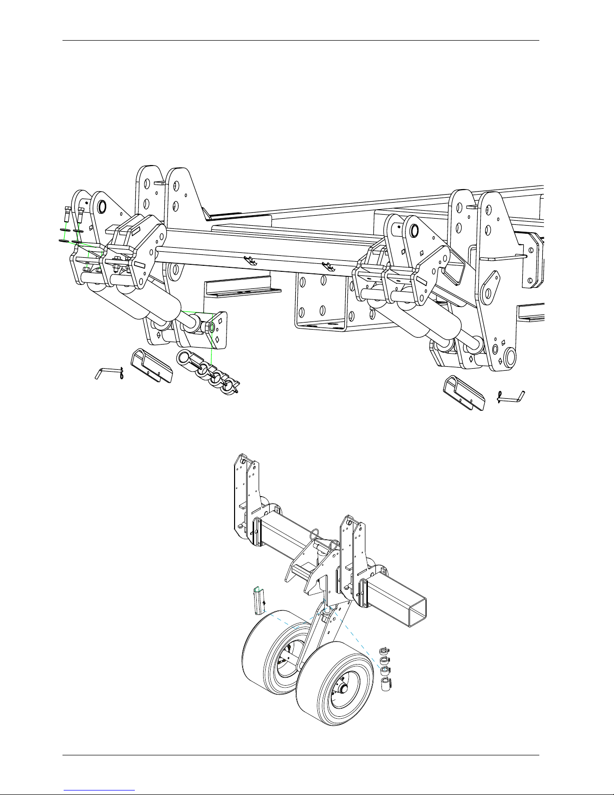
1.5 Transport locks
The machine is equipped with transport locks and depth stop collars. Remove
the transport locks (1) and depth stop collars (2) before moving the machine
on roads. When not in use, keep the transport locks and depth stop collars in
the storage position (3). Install transport locks when machine is completely
unfolded before doing any maintenance or service work.
CENTER SECTION
3
2
1
700187
WING SECTION
3
1
2
701405
1.
22
Safety
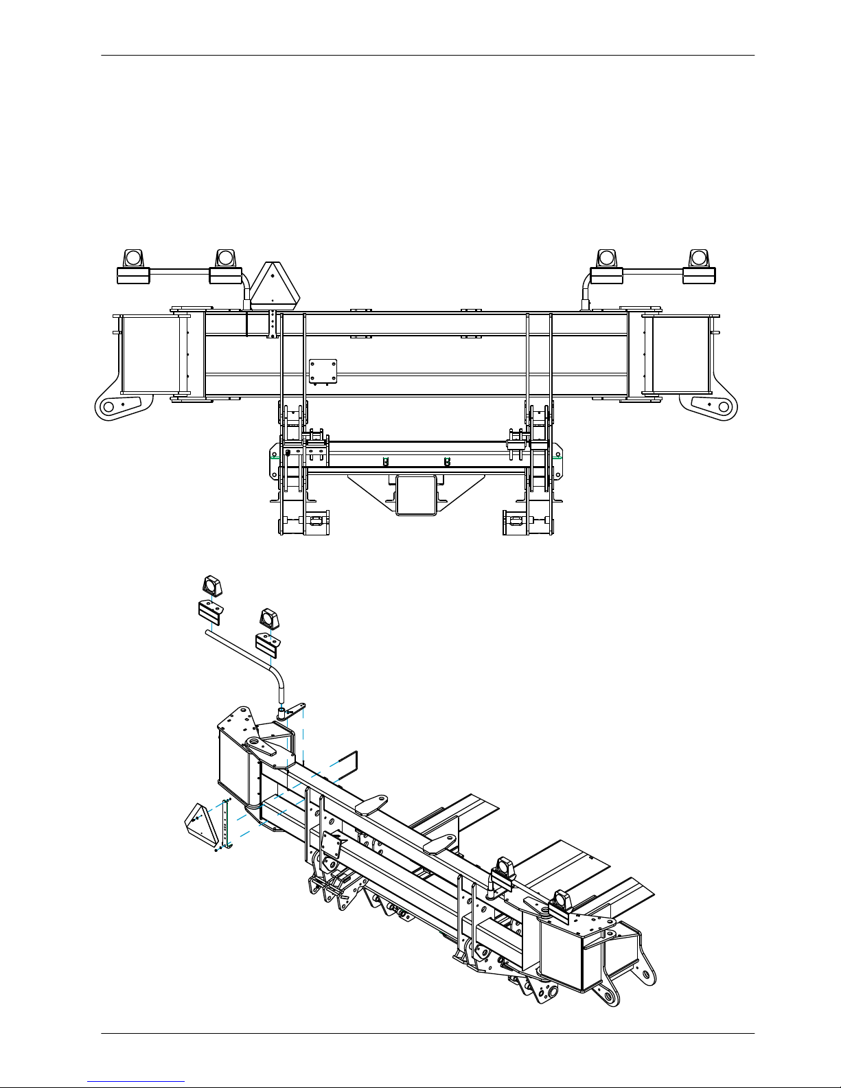
1.6 Marker lamps
The machine has marker lamps that must be used when moving the
machine in the folded position on roads.
The machine is equipped with two red lamps (1) located toward the
rear center of the machine.
The machine is equipped with two amber lamps (2) located toward the
rear center of the machine.
2
1
2
1
AMBER LIGHTGHT
(223143)
12 X 36 LIGHT ARM
(235460)
SMV EMBLEM
(30651)
SMV BRACETKET
(350933)
RED LIGHTGHT
(223144)
LIGHT BRACKETKET
(223126)
LONG BASE PIVOT
(223131)
3/8 X 7 X 8-1/4
U-BOLT (89277)
701406
701406 ISO
243812 10K DECAL
23
700730610 SAFETY SIGNDANGER CRUSHING
22372 AMBER
REFLECTOR
700730781 WARNING LOCKOUT
DANGER
700730610
700730619 WARNING
CRUSHING
700730610 DANGER
CRUSHING
DANGER
700730610
WAR NI NG
1. Safety
700730781
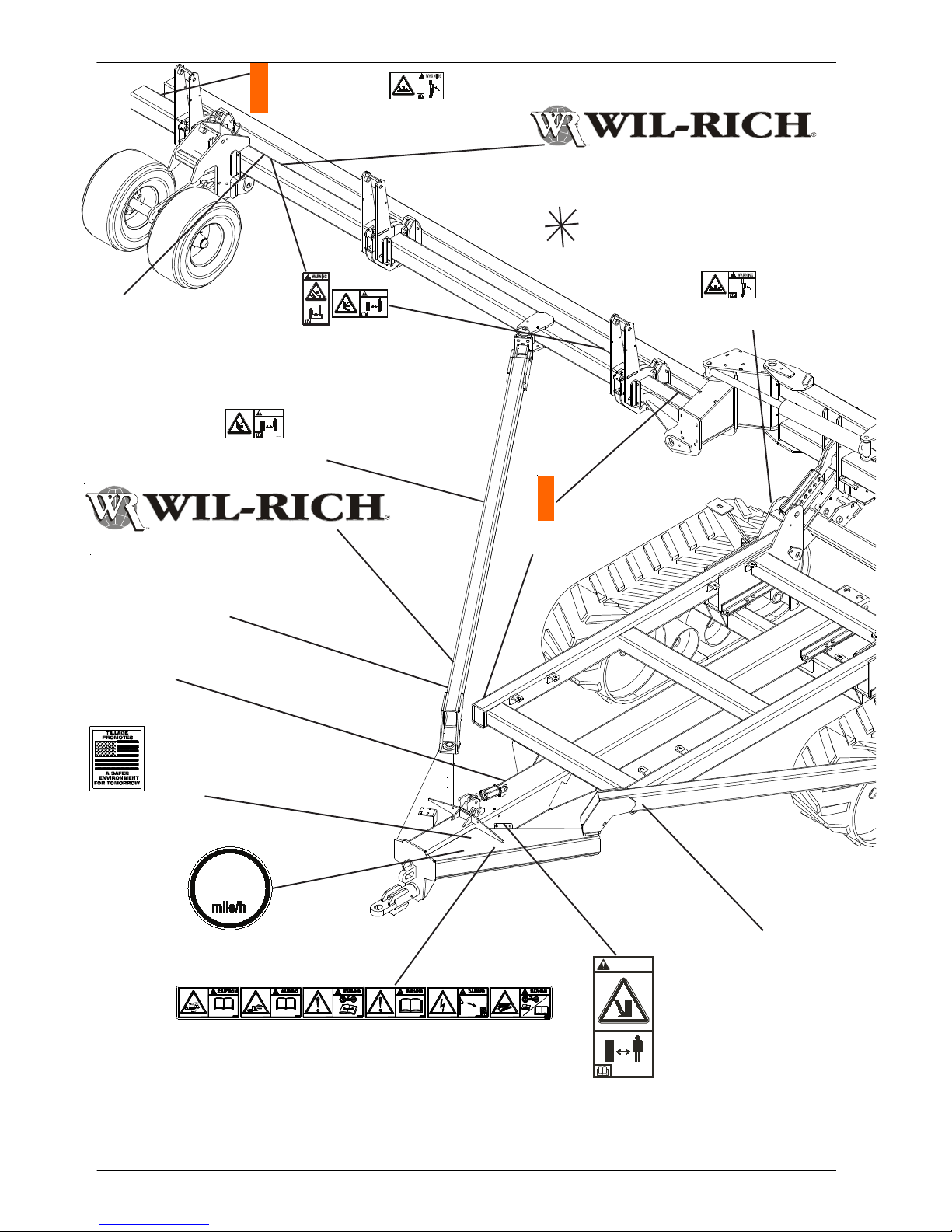
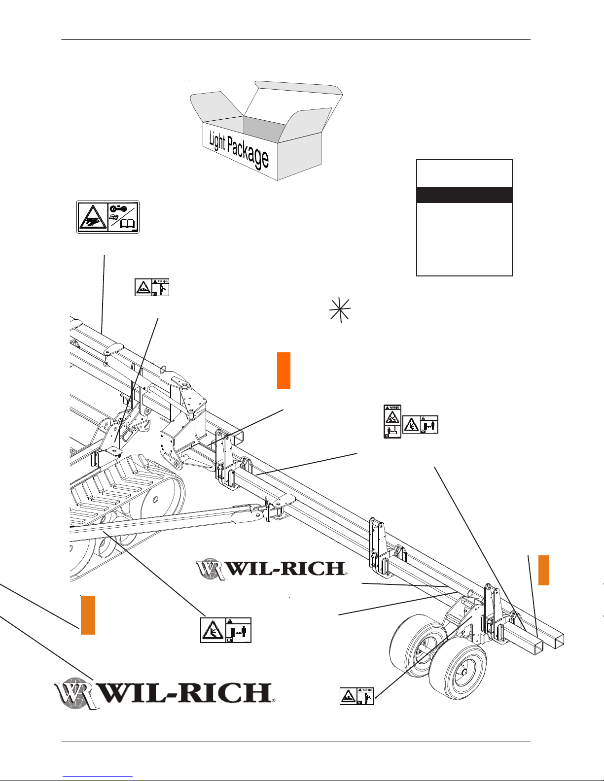
1.7 Safety sign location
65342 WIL-RICH DECAL
ALL DECALS F ACING
REAR ON THE WINGS
ARE PLACED ON THE
MAIN BAR
WAR NI NG
700730781
700730781 WARNING LOCKOUT
65342 WIL-RICH DECAL
243812 10K DECAL
SERIAL NUMBER
LOCA TION
997263 TILLAGE
SAFE ENVIRONMENT
5
1
700731295
DECAL 15 MPH
22372 AMBER
REFLECTOR
WAR NING
9971 163 SAFETY DECAL SET
243812 10K DECAL
700731801
700731801 SAFETY SIGNWARNING CRUSHING (LOCATE ON HYDRAULIC JACK
TUBE)
23
700730610
DANGER
700730781
WARNING
700730781
WARNING
700730610
DANGER
1. Safety
24
1.7 Safety sign location
997267 FLUID UNDER
PRESSURE
41426 CLEARANCE LIGHT PACKAGE
2
74283 ASSY/OPERA TORS
MANUAL
ASSEMBLY/OPERATORS
MANUAL
WIL-RICH
FOLDING
TOOLBAR
700730781 WARNING LOCKOUT
ALL DECALS F ACING REAR ON THE
WINGS ARE PLACED ON THE MAIN BAR
22372 AMBER
REFLECTOR
700730619 WARNING
CRUSHING
700730610 DANGER
CRUSHING
22372 AMBER
REFLECTOR
65342 WIL-RICH DECAL
22372 AMBER
REFLECTOR
700730610 SAFETY SIGNDANGER CRUSHING
65342 WIL-RICH DECAL
243812 10K DECAL
700730781 WARNING LOCKOUT
9971163 SAFETY DECAL SET
25
Warning/lockout
Hazard (A): Crushing hazard. Toolbar frame
movement.
Avoidance (B): Stay clear of this area while
engine and machine are operating. For service
work, install the wing lock pins before getting under
the wing.
1. Safety
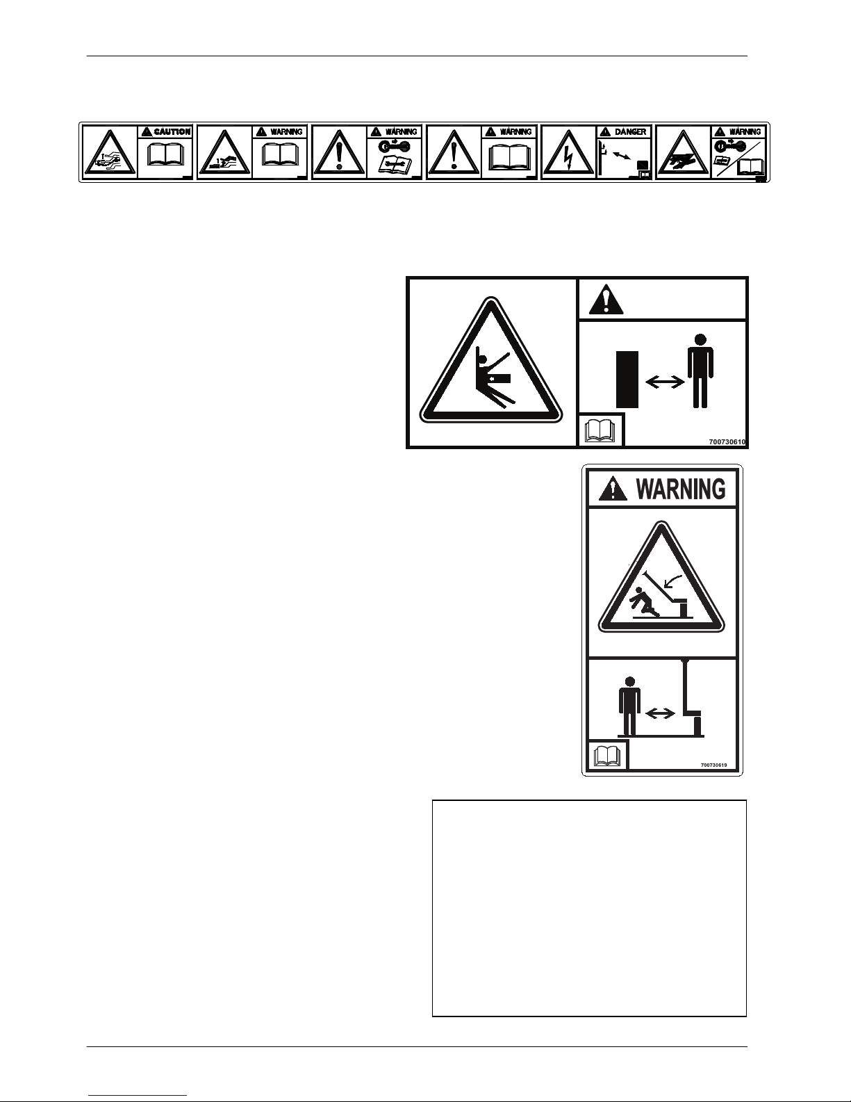
1.7 Safety sign location
DANGE R
700730610
Warning/lockout
Hazard (A): Crushing hazard. Toolbar rotation -
row unit.
Avoidance (B): Stay clear of this area while
engine and machine are operating. For service
work, install the wing lock pins before getting under
the wing.
(1) Danger/folding wings
Hazard (A): Overhead crushing hazard from
lowering or falling wing.
700730610
700730619
Avoidance (B): Stay clear of this area while engine
and machine are operating. For service work,
install the wing lock pins before getting under the
wing.
Fig. 27

1. Safety
26
(2) Warning/lockout
Hazard (A): Crushing hazard.
Avoidance (B): Stay clear of this area while engine
and machine are operating. For service work,
install the wing lock pins before getting under the
wing.
Fig. 27
700730781
(3) Caution/safety chains
Hazard (A): Loss of machine control.
Avoidance (B): Install the safety chains when
connecting the machine to the tractor. Read the
operators manual for safety information and the
operating instruction before operating the
machine.
Fig. 28
Fig. 28
Fig. 29

(4) Warning/negative tongue weight
27
Hazard (A): Negative tongue weight will cause the
tongue to rise immediately when disconnecting
the machine.
Avoidance (B): Stay clear of the tongue when
disconnecting the machine from the tractor. Read
the operators manual for safety information and
operating the instructions before operating the
machine.
1. Safety
Fig. 29
(5) Warning/remove key
Hazard (A): General safety alert.
Avoidance (B): Turn off the machine and remove
the key before maintenance or repair.
Fig. 30
Fig. 30
Fig. 31

1. Safety
28
(6) Warning/read operators manual
Hazard (A): General safety alert.
Avoidance (B): Read and understand the
operators manual before operating the machine.
Fig. 31
(7) Danger/high line
Hazard (A): Electrical shock hazard - risk of
personal injury and component damage.
Avoidance (B): Keep the correct distance away
from electrical power lines.
Fig. 32
Fig. 32
Fig. 33

(8) Warning/hydraulic fluid pressure
29
Hazard (A): Injection hazard into skin - escaping
fluid under high pressure.
Avoidance (B): Turn off the engine, remove the
key, relieve the pressure before maintenance or
repair. Refer to the operator manual for the correct
service procedures.
1. Safety
Fig. 33
997867
(9) Maximum speed
The maximum speed safety sign displays the
maximum speed to transport the machine.
Fig. 34
Fig. 34
700731295
15
Fig. 35

1. Safety
30
(10) Reflector/yellow
Tillage safe environment
22372
Fig. 36
997263
Warning sign
Hazard (A): Foot crushing hazard part may lower
without warning.
Avoidance (B): Turn off the engine, remove the
key, relieve the pressure before maintenance or
repair. Refer to the operator manual for the correct
service procedures.
700731801
WARNING
A
B
700731801
 Loading...