

Page 1

Wilo-Sub TWI 4-6
D Einbau- und Betriebsanleitung
GB Installation and operating instructions
F Notice de montage et de mise en service
E Instrucciones de instalación y funcionamiento
TR Montaj ve kullanma kılavuzu
RUS Инструкция по монтажу и эксплуатации
SK Návod na montáž a obsluhu
4 069 717-Ed.03/2008-01-Wilo!
Page 2
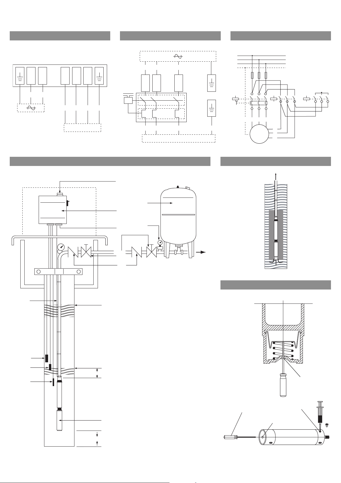
Fig.1: Fig.2: Fig.3:
L1
L2
L3
UV W
L
N
PE
abc d
M 1 ~
dbca
M 3 ~
Fig.4: Fig.5:
9
ad b c
M 3 ~
c
a
b
11
8
10
12
13
Fig.6:
5
4
3
2
7
6
Min. 0,20
E
1
0,30 - 1,00 m
D
C
E
Page 3

D Einbau- und Betriebsanleitung 3
GB Installation and operating instructions 10
F Notice de montage et de mise en service 17
E Instrucciones de instalación y funcionamiento 25
TR Montaj ve kullanma kılavuzu 33
RUS Инструкция по монтажу и эксплуатации 40
SK Návod na montáž a obsluhu 48
Page 4

Page 5
Deutsch
Einbau- und Betriebsanleitung
1 Allgemeines
Über dieses Dokument
Die Einbau- und Betriebsanleitung ist Bestandteil
des Produktes. Sie ist jederzeit in Produktnähe
bereitzustellen. Das genaue Beachten dieser
Anweisung ist Voraussetzung für den bestimmungsgemäßen Gebrauch und die richtige Bedienung des Produktes.
Die Einbau- und Betriebsanleitung entspricht der
Ausführung des Produktes und dem Stand der
zugrunde gelegten sicherheitstechnischen Normen bei Drucklegung.
2Sicherheit
Diese Betriebsanleitung enthält grundlegende
Hinweise, die bei Aufstellung und Betrieb zu
beachten sind. Daher ist diese Betriebsanleitung
unbedingt vor Montage und Inbetriebnahme vom
Monteur sowie dem zuständigen Betreiber zu
lesen.
Es sind nicht nur die unter diesem Hauptpunkt
Sicherheit aufgeführten allgemeinen Sicherheitshinweise zu beachten, sondern auch die unter den
folgenden Hauptpunkten mit Gefahrensymbolen
eingefügten, speziellen Sicherheitshinweise.
2.1 Kennzeichnung von Hinweisen in der
Betriebsanleitung
2.2 Personalqualifikation
Das Personal für die Montage muss die entsprechende Qualifikation für diese Arbeiten aufweisen.
2.3 Gefahren bei Nichtbeachtung der
Sicherheitshinweise
Die Nichtbeachtung der Sicherheitshinweise kann
eine Gefährdung für Personen und Pumpe/Anlage
zur Folge haben. Die Nichtbeachtung der Sicherheitshinweise kann zum Verlust jeglicher Schadenersatzansprüche führen.
Im Einzelnen kann Nichtbeachtung beispielsweise
folgende Gefährdungen nach sich ziehen:
• Versagen wichtiger Funktionen der Pumpe/
Anlage,
• Versagen vorgeschriebener Wartungs- und Reparaturverfahren
• Gefährdungen von Personen durch elektrische,
mechanische und bakteriologische Einwirkungen,
• Sachschäden.
2.4 Sicherheitshinweise für den Betreiber
Die bestehenden Vorschriften zur Unfallverhütung sind zu beachten.
Gefährdungen durch elektrische Energie sind auszuschließen. Weisungen lokaler oder genereller
Vorschriften [z.B. IEC, VDE usw.] und der örtlichen
Energieversorgungsunternehmen sind zu beachten.
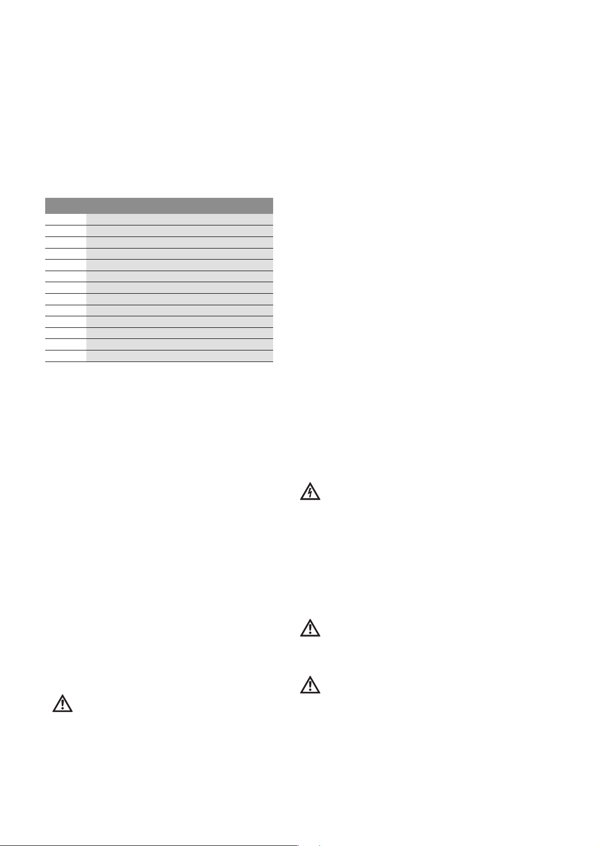
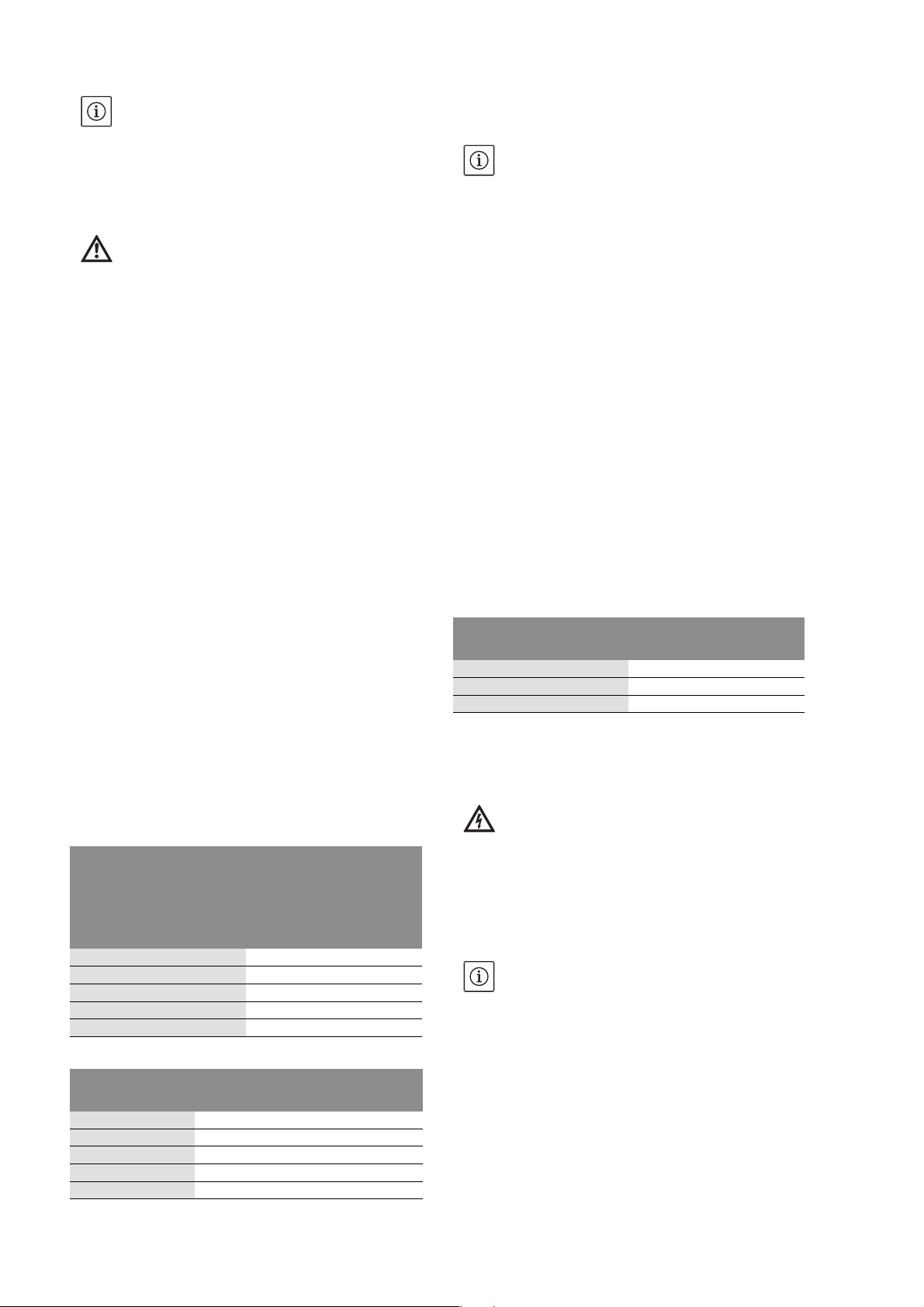
Symbole:
Allgemeines Gefahrensymbol
Gefahr durch elektrische Spannung
NÜTZLICHER HINWEIS
Signalwörter:
GEFAHR!
Akut gefährliche Situation.
Nichtbeachtung führt zu Tod oder schwersten
Verletzungen.
WARNUNG!
Der Benutzer kann (schwere) Verletzungen
erleiden. 'Warnung' beinhaltet, dass (schwere)
Personenschäden wahrscheinlich sind, wenn der
Hinweis missachtet wird.
VORSICHT!
Es besteht die Gefahr, die Pumpe/Anlage zu
beschädigen. 'Vorsicht' bezieht sich auf mögliche Produktschäden durch Missachten des Hinweises.
2.5 Sicherheitshinweise für Inspektions- und
Montagearbeiten
Der Betreiber hat dafür zu sorgen, dass alle
Inspektions- und Montagearbeiten von autorisiertem und qualifiziertem Fachpersonal ausgeführt werden, dass sich durch eingehendes
Studium der Betriebsanleitung ausreichend informiert hat.
Die Arbeiten an der Pumpe/Anlage dürfen nur im
Stillstand durchgeführt werden.
2.6 Eigenmächtiger Umbau und
Ersatzteilherstellung
Veränderungen der Pumpe/Anlage sind nur nach
Absprache mit dem Hersteller zulässig. Originalersatzteile und vom Hersteller autorisiertes Zubehör
dienen der Sicherheit. Die Verwendung anderer
Teile kann die Haftung für die daraus entstehenden Folgen aufheben.
2.7 Unzulässige Betriebsweisen
Die Betriebssicherheit der gelieferten Pumpe/
Anlage ist nur bei bestimmungsgemäßer Verwendung entsprechend Abschnitt 4 der Betriebsanleitung gewährleistet. Die im Katalog/Datenblatt
angegebenen Grenzwerte dürfen auf keinen Fall
unter- bzw. überschritten werden.
HINWEIS: Ein nützlicher Hinweis zur Handhabung
des Produktes. Er macht auch auf mögliche
Schwierigkeiten aufmerksam.
Einbau- und Betriebsanleitung Wilo-Sub TWI4-6 3
Page 6
Deutsch
3 Transport und Zwischenlagerung
Sofort nach Erhalt des Produkts:
• Produkt auf Transportschäden überprüfen,
• Bei Transportschäden die notwendigen Schritte
innerhalb der entsprechenden Fristen beim Spediteur einleiten.
VORSICHT! Gefahr vor Sachschäden!
Unsachgemäßer Transport und unsachgemäße
Zwischenlagerung können zu Sachschäden am
Produkt führen.
• Die Pumpe darf zum Transport nur an dem dafür
vorgesehenen Bügel aufgehängt / getragen
werden. Niemals am Kabel!
• Die Pumpe ist bei Transport und Zwischenlagerung gegen Feuchtigkeit, Frost, Hitze, direkter
Sonneneinstrahlung und mechanischer Beschädigung zu schützen.
• Der Druckstutzen der Pumpe ist bei der Lagerung fest zu verschließen, um Verunreinigungen
zu vermeiden.
• Bei Transport und Zwischenlagerung muss
beachtet werden, dass der Gefrierpunkt der
Motorfüllung bei -8°C liegt.
• Alle Stromzuführungsleitungen sind gegen
Abknicken, Beschädigungen und Feuchtigkeitseintritt zu schützen.
• Die Pumpe ist horizontal auf festen, ebenen
Grund zu lagern.
4 Bestimmungsgemäße Verwendung
Die Unterwassermotorpumpen Wilo-Sub TWI sind
geeignet zur Förderung von sauberem oder leicht
verschmutztem Wasser ohne langfaserige und
abrasive Bestandteile.
Sie werden eingesetzt
• für Bohrlöcher und Zisternen,
• zum Pumpen und Verteilen von Brauchwasser für:
• den Hausgebrauch (Trinkwasserversorgung)
• die Landwirtschaft (Bewässerung, Beregnung)
• die Industrie (Druckerhöhung etc.)
HINWEIS: Zum jeweiligen Einsatzfall sind die örtlichen Vorschriften zu beachten.
Die Pumpen werden ausschließlich überflutet
(getaucht) aufgestellt und können horizontal mit
Kühlmantelrohr und vertikal installiert werden.
VORSICHT! Gefahr vor Sachschäden! Das Fördern unzulässiger Stoffe kann zu Sachschäden
am Produkt führen.
Die Pumpen sind nicht geeignet für Wasser mit
groben Verunreinigungen wie Fasern oder
brennbare Flüssigkeiten sowie für den Einsatz in
explosionsgefährdeten Bereichen.
Zur bestimmungsgemäßen Verwendung gehört
auch die Einhaltung dieser Anleitung.
Jede darüber hinausgehende Verwendung gilt als
nicht bestimmungsgemäß.
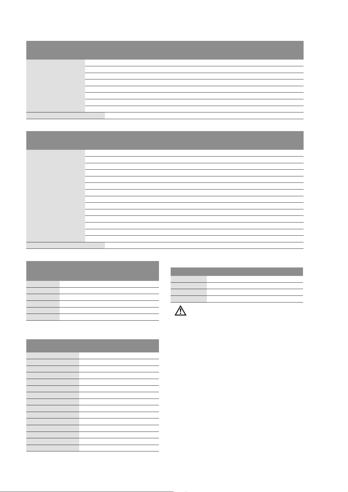
5 Angaben über das Erzeugnis
5.1 Typenschlüssel (Standard-Variante)
Beispiel: WILO-Sub TWI 4.01-09-B EM
TWI Unterwassermotor-Pumpe
4 bzw. 6 Mindestdurchmesser:
Bohrlochdurchmesser 4" und 6“
Pumpendurchmesser max. 98 mm bei 4“, max.
152mm bei 6“
.01 Nennvolumenstrom (m³/h)
-09
-B Pumpengeneration
EM EM = Wechselstrom 1~230V (50Hz/60Hz) mit
5.2 Technische Daten 50Hz 60Hz
Zulässige Bestandteile der
Fördermedien:
Netzspannung: 1~230V (4“),
Schutzart: IP 68
Max. Fördermenge:
Max. Förderhöhe: 4“ = 320 m
Druckstutzen: 1¼“, 1½“, 2“ bei 4“ Hydraulik
Zul. Temperaturbereich des
Fördermediums:
Max. Tauchtiefe: 350 m
Max. Schalthäufigkeit:
Stufenzahl der Pumpe
Anlaufgerät
DM = Drehstrom 3~400V (50Hz), 3~480V (60
Hz)
SD = Drehstrom, Stern-Dreieck-Anlauf (nur
6“-Motoren)
max. Sandgehalt 50 g/m³
1~230V (4“)
3~400V (4“,
6“)
4“ = 20 m³/h
6“ = 78 m³/h
6“ = 410 m
2½“, 3“ bei 6“ Hydraulik
+3 bis 30 °C
20/h
5.3 Lieferumfang (Standard-Variante)
• Unterwassermotorpumpe
• integriertem Rückflussverhinderer
• Anschlusskabel
• 1,5 m, 2,5 oder 5 m langes, lösbares Anschlusskabel (4x1,5mm²) bei 4“-Motoren oder
• 4 m langem Anschlusskabel (4x4mm²) bei 6“Motoren
• 230 V inkl.:
• Schaltkasten mit Kondensator
• integriertem thermischem Motorschutz
• Ein-, Ausschalter
HINWEIS: Die elektrischen Verbindungen erfolgen
werkseitig.
• Einbau- und Betriebsanleitung
5.4 Zubehör (optional):
• Rückflussklappe am Ausgang des Bohrloches
• Trockenlaufschutz: Schwimmerschalter oder
Elektrode
• WILO-ER Schaltgerät (Motorschutz + Wasserstandsüberwachung)
• Motorkabel: als Bausatz (incl. Stecker) oder als
Meterware (ohne Stecker)
3~480V (4“,
6“)
4“ = 25 m³/h
6“ = 97 m³/h
4“ = 340 m
6“ = 520 m
4 WILO AG 01/2008
Page 7
Deutsch
• Schrumpfschläuche, oder Vergußmuffen (zur Verlängerung des Motorkabels)
• Druck-, Vorratsbehälter
• WILO-Fluidcontrol oder WILO-Druckschaltung ER
als Plug & Pump Pakete (siehe gesonderte EBA)
6 Beschreibung und Funktion
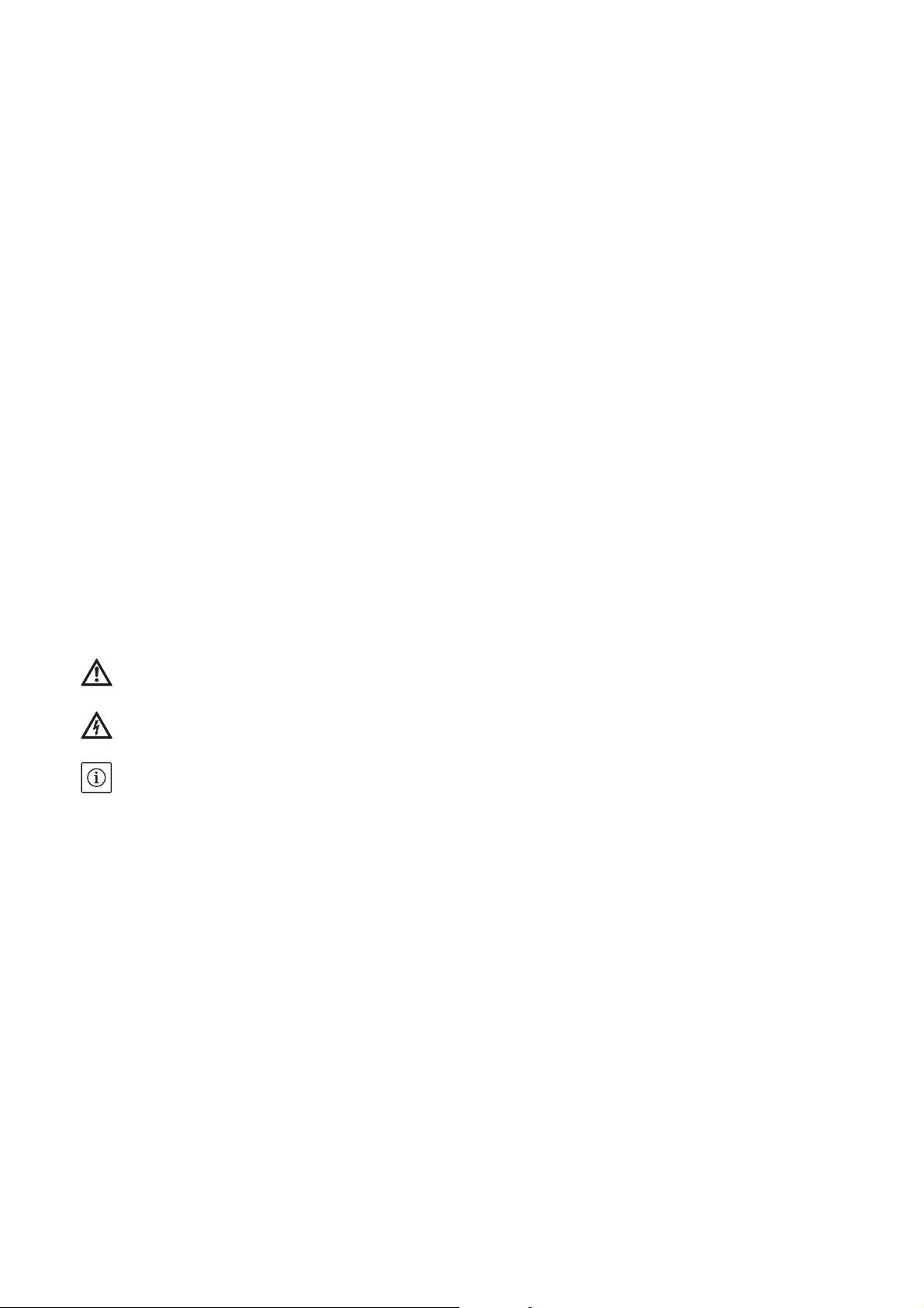
6.1 Beschreibung der Pumpe (Fig. 4)
Pos. Bauteil-Beschreibung
1 Pumpe Wilo-Sub in DM Ausführung
2
3
4 Tauch-Elektrode Oberes Niveau
5
6
7 Statisches Niveau (Pumpe abgeschaltet)
8
9
10 Druckschalter mit Manometer
11
12
13 Rückflußverhinderer
Tauch-Elektrode Masse
Tauch-Elektrode Wassermangel
Motor-Anschlußkabel
Dynamisches Niveau (Pumpe in Betrieb)
Schaltkasten (mit Trockenlaufschutz)
Netzanschluss / Spannungsversorgung
Druck-/Vorratsbehälter
Absperrarmatur
Vollüberflutbare, mehrstufige Unterwassermotorpumpe mit radialen oder halb-axialen Laufrädern. Kupplung und Flansche verwendbar für
Motoren mit Pumpe, Einbauabmessungen in
Übereinstimmung mit NEMA-Standards. Eingebauter Rückflussverhinderer im Pumpenkopf.
Zwischenlager in jeder Stufe, speziell konstruiert,
um die Wellenlagerung zu optimieren. Robuster
Kabelschutz. Hydraulikbauteile zur Erzielung von
hohen Wirkungsgraden optimiert. Hohe Beständigkeit gegen Korrosion und Abrasion, die durch
Eigenschaften des Edelstahls erreicht werden.
Leichter Service durch einfache Demontage- und
Montageeigenschaften des Aggregates.
Korrosionsfreier Wechsel- oder Drehstrommotor
mit lackisolierten Wicklungen in hermetisch vergossenem Stator für Direktanlauf mit selbstschmierenden Lagern.
Die Motorkühlung erfolgt durch Übertragung der
Verlustwärme auf das Fördermedium um den
Außenmantel des Motors. Die Mindestfließgeschwindigkeit des Fördermediums entlang des
Motors beträgt beim 4“-Motor 10cm/sec und
beim 6“-Motor 16cm/sec.
6.2 Sanftanlauf und Frequenzumrichter
Im Allgemeinen können alle Motoren in Kombination mit Frequenzumrichtern und elektronischen
Startern (Sanftanlauf), innerhalb der nachfolgend
beschriebenen Grenzen, betrieben werden.
VORSICHT! Gefahr vor Sachschäden!
Wenn diese Einsatzbedingungen nicht erfüllt
sind reduziert sich die Lebensdauer der Pumpe
und kann zur Zerstörung des Motors führen!
6.2.1 Bedingungen bei Verwendung von
elektronischen Startern (Sanftanlauf)
• Die minimale erforderliche Kühlfließgeschwindigkeit muss bei sämtlichen Betriebspunkten
gewährleistet sein (4“-Motoren - 10cm/sec, 6“Motoren - 16cm/sec.)
• Die Stromaufnahme muss während des gesamten
Betriebs unterhalb des Nennstromes (In) (siehe
Typenschildangabe) liegen.
• Die Rampenzeit für die Anlauf-/Stopvorgänge
zwischen 0 und 30 Hz ist auf maximal 1 sec. einzustellen. Die Rampenzeit zwischen 30 Hz und der
Nennfrequenz ist auf maximal 3 sec. einzustellen.
• Die Spannung beim Start muss mindestens 55%
der Motornennspannung betragen.
• Zur Vermeidung von Verlustleistungen während
des Betriebs, den elektronischen Starter (Sanftanlauf) nach Erreichen des Normalbetriebs überbrücken.
6.2.2 Bedingungen bei Verwendung von
Frequenzumrichter
• Dauerbetrieb kann nur zwischen 30 Hz und 50 Hz
(60Hz) gewährleistet werden.
• Zur Abkühlung der Motorwicklung wird eine Zeitspanne von mindestens 60 sec. zwischen Pumpenstop und Neustart empfohlen.
• Nie den Nennstrom (siehe Typenschildangabe)
überschreiten.
Maximale Spannungsspitze: 1000V
Maximale Spannungsanstiegsgeschwindigkeit:
500V/µs
• Zusätzliche Filter sind erforderlich, wenn die
erforderliche Steuerspannung 400 V überschreitet.
• Die Spannung beim Start muss mindestens 55%
der Motornennspannung betragen.
7 Installation und elektrischer Anschluss
GEFAHR! Lebensgefahr!
Unsachgemäße Installation und unsachgemäßer
elektrischer Anschluss können lebensgefährlich
sein.
• Installation und elektrischen Anschluss nur
durch Fachpersonal und gemäß geltender Vorschriften durchführen lassen!
• Vorschriften zur Unfallverhütung beachten!
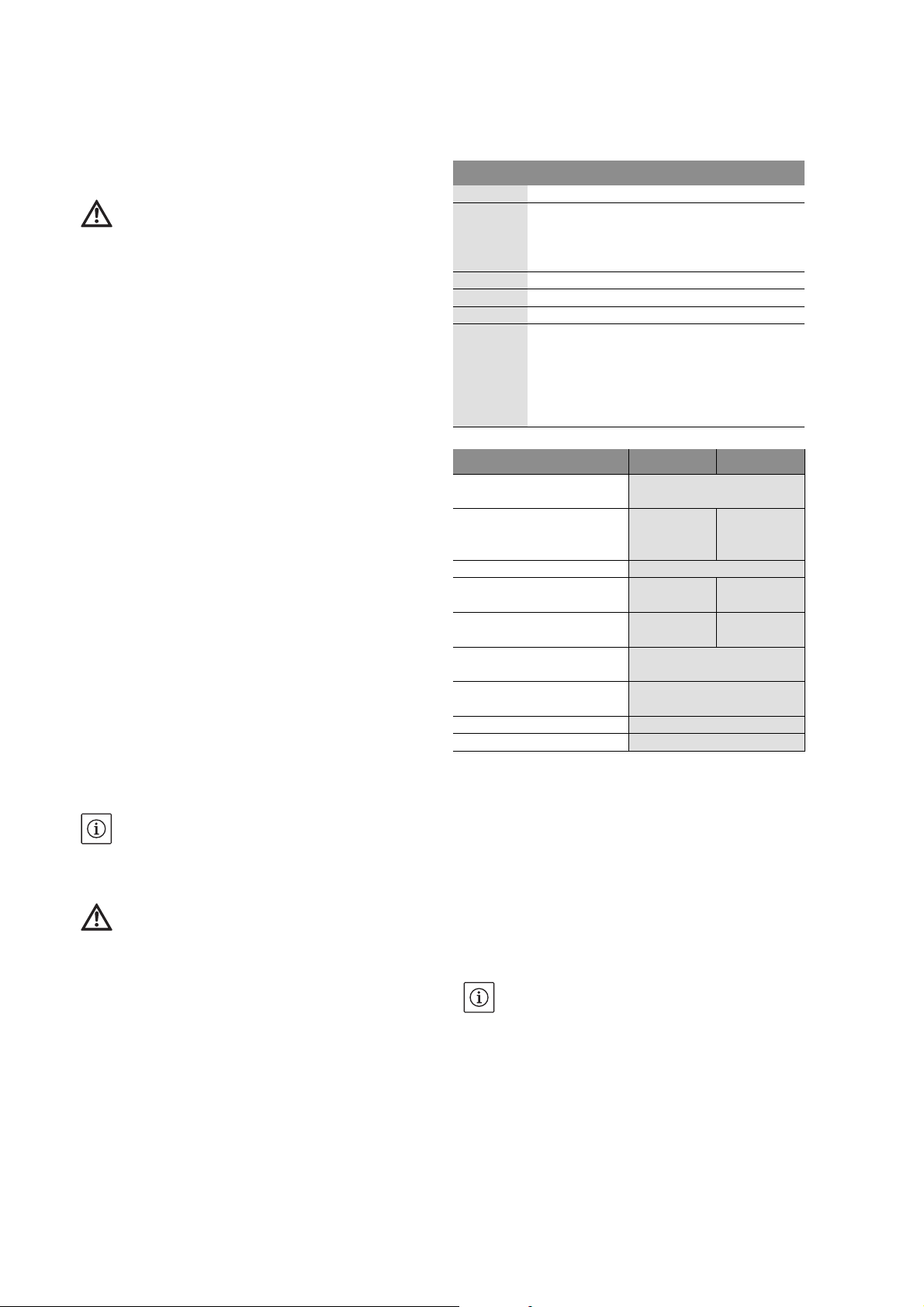
7.1 Installation.
Die Pumpe kann vertikal oder horizontal mit Kühlmantelrohr eingebaut werden.
VORSICHT! Gefahr vor Sachschäden!
Gefahr der Beschädigung durch unsachgemäße
Handhabung. Die Bohrlöcher oder Pumpstationen müssen nach den allgemein gültigen technischen Regel an-, ausgelegt werden.
VORSICHT! Gefahr vor Sachschäden!
Im Falle einer Installation in einem Bohrloch > 4“
bzw. 6“ (siehe Fig. 4) oder einem Vorratsbehälter bei horizontalem Einbau muss unbedingt ein
Wasserführungsmantel um Pumpe und Motor
Einbau- und Betriebsanleitung Wilo-Sub TWI4-6 5
Page 8
Deutsch
angebracht werden, um eine ausreichende Kühlung des Motors zu gewährleisten!
• Für 4“ Pumpen mit Nennvolumenstrom >9 m³/h
wird ein 6“ Bohrloch empfohlen, für 6“ Pumpen
>30 m³/h Nennvolumenstrom ein 8“ Bohrloch.
• Der Wasserzufluß im Bohrloch oder Brunnen muss
ausreichend für die Förderleistung der Pumpe
sein.
• Die Pumpe wird mit Hilfe eines Flaschenzuges mit
Kette und Dreifuß, schwere Pumpen mittels Seilwinde herabgelassen. Die Installation sollte
außerhalb des Wasserzulaufs bzw. des Filterrohres
erfolgen.
• Die Pumpe darf niemals trocken laufen. Dazu muss
sichergestellt werden, dass selbst in Trockenperioden der Wasserspiegel niemals unterhalb der
Oberkante des Aggregates absinkt.
• Um ein freies Herablassen der Pumpe gewährleisten zu können, ist ein gleichbleibender Rohrinnendurchmesser von 4“ (102 mm) bzw. 6“ (152
mm) sicherzustellen.
• Die Pumpe darf niemals am elektrischen Kabel
herabgelassen bzw. hochgezogen werden.
• Der elektrische Anschluss sowie Verlängerung des
Motorkabels, muss vor dem Herablassen der
Pumpe vorgenommen werden.
• Die Pumpe muss mind. 0,30 m über dem Boden
des Brunnens oder des Bohrloches installiert werden (Fig. 4).
• Das Anlagentypenschild muss in der Nähe des
Bohrloches angebracht sein, um Zugang zu den
technischen Daten der Anlage zu haben.
• Vor dem Herablassen (und während des Ablassens
in tiefe Bohrlöcher) muss der Isolationswiderstand
am Motor und am Kabel geprüft werden (mind. 2 M
Ω).
• Die Pumpe kann mittels einer fest en oder flexiblen
Rohrleitung in der Nennweite 1¼“ bis 3“, je nach
Pumpenausführung angeschlossen werden.
• Bei Einsatz von flexiblen Rohrleitungen muss die
Pumpe durch ein Sicherungsseil gehalten werden.
Hierzu sind die Stahlösen am Pumpenkopf zu
benutzen. Feste Rohrleitungen sind zu bevorzugen.
• Es wird empfohlen am Ausgang des Bohrloches
einen zusätzlichen Rückflussverhinderer, sowie
eine Absperrarmatur vorzusehen.
VORSICHT! Gefahr vor Sachschäden!
Bei erhöhtem Wasserdruck (>180 m Ws) muss
direkt am Pumpenauslass ein Rückflussverhinderer installiert werden. Der Rückflussverhinderer muss für einen zulässigen Betriebsdruck
von mind. 20 bar ausgelegt sein!
• Es muss die erforderliche Motorkühlung beachtet
werden (siehe Tabelle bei Punkt “Mediumstemperatur“)!
7.2 Elektrischer Anschluss
GEFAHR! Lebensgefahr!
Bei unsachgemäßem elektrischem Anschluss
besteht Lebensgefahr durch Stromschlag.
Elektrischen Anschluss nur durch vom örtlichen
Energieversorger zugelassenen Elektroinstallateur und entsprechend den örtlich geltenden
Vorschriften ausführen lassen.
• Strom und Spannung des Netzanschlusses müssen den Angaben auf dem Typenschild entsprechen.
• Anschlusskabel gemäß geltenden Normen/Vorschriften benutzen und gemäß des Klemmanschlussplanes des Schaltgerätes oder
Schaltschrankes anschließen.
VORSICHT! Gefahr vor Sachschäden!
Die max. Länge des Kabels ist abhängig von der
Nennstromaufnahme des Motors und vom
Kabelquerschnitt!
Vor Anschluss des Kabels anhand der Tabelle die
Länge und den Durchmesser überprüfen!
Durchmesser und max. Längen des Kabels bei Direkt Anlauf:
Motorausführung Motor Kabel
kW 4 x 1,5 mm² 4 x 2,5 mm² 4 x 4 mm² 4 x 6 mm² 4 x 10 mm² 4 x 16 mm²
EM
1~ 50/60Hz 230V
DM
3~ 50Hz 400V
3~ 60Hz 480V
Kabelgewicht (kg/m) 0,20 0,25 0,30 0,40 0,65 0,85
0,25100---------0,3785144-------0,55 64 107 140 -- -- -0,75 49 83 110 165 -- -1,10 32 54 80 120 195 -1,50 25 35 60 95 153 245
2,20 17 25 45 65 102 163
0,37 661 1102 1764 2646 4411 7057
0,55 454 758 1213 1819 3032 4852
0,75 341 569 911 1367 2279 3647
1,10 245 409 655 983 1639 2623
1,50 179 299 478 718 1196 1915
2,20 121 202 324 486 811 1298
3,00 94 157 252 378 630 1008
3,70 76 128 204 307 512 819
4,00 70 118 188 283 472 755
5,50 52 87 140 210 351 562
7,50 39 65 104 157 261 418
6 WILO AG 01/2008
Page 9
Durchmesser und max. Längen des Kabels bei Direkt Anlauf:
Motorausführung Motor Kabel
kW 4 x 1,5 mm² 4 x 2,5 mm² 4 x 4 mm² 4 x 6 mm² 4 x 10 mm² 4 x 16 mm²
DM
3~ 50Hz 400V
3~ 60Hz 480V
Kabelgewicht (kg/m) 0,20 0,25 0,30 0,40 0,65 0,85
Durchmesser und max. Längen des Kabels (6“-Motoren) bei Stern-Dreieck Anlauf:
Motorausführung Motor Kabel
DM
3~ 50Hz 400V
3~ 60Hz 480V
Kabelgewicht (kg/m) 0,20 0,25 0,30 0,40 0,65 0,85
9,30 32 54 87 130 217 348
11,00 -- 45 72 109 181 291
15,00 -- -- 54 81 135 216
18,50 -- -- 44 66 110 176
22,00 -- -- -- 55 92 147
30,00--------67108
37,00----------89
45,00----------73
kW 4 x 1,5 mm² 4 x 2,5 mm² 4 x 4 mm² 4 x 6 mm² 4 x 10 mm² 4 x 16 mm²
2,20 182 304 486 730 1217 1947
3,00 141 236 378 567 945 1513
3,70 115 192 307 461 768 1229
4,00 106 177 283 425 708 1133
5,50 79 131 210 316 527 843
7,50 58 98 157 235 392 628
9,30 48 81 130 195 326 522
11,00 40 68 109 163 272 436
15,00 30 50 81 121 203 324
18,50 24 41 66 99 165 264
22,00 -- 34 55 83 138 221
30,00 -- -- 40 60 101 162
37,00 -- -- -- 50 83 134
45,00--------68109
Deutsch
1~ 230 V (50Hz, 60Hz), EM-Version (Fig. 1)
Leistung Stromaufnahme
230V
kW A µF
0,37 3,2 16
0,55 4,3 20
0,75 5,3 30
1,10 7,8 40
1,50 9,9 50
2,20 14,9 75
3~400V 50Hz, 3~480V 60Hz, DM-Version
(Fig. 2 / 3)
Leistung Stromaufnahme 400/480 V
kW A
0,37 1,3
0,55 1,7
0,75 2,2
1,10 3,2
1,50 4,0
2,20 5,9
3,00 7,8
3,70 9,1
4,00 10,0
5,50 13,7
7,50 18,0
9,30 20,3
11,00 23,3
15,00 31,3
18,50 38,5
BetriebsKondensator
Anschlüsse
(Aderkennzeichnung)
Fig. 1 - 3
aschwarz
bblau / grau
cbraun
dgrün / gelb
VORSICHT! Gefahr vor Sachschäden!
Bei nicht ordnungsgemäßem Anschluss des
Motors kann dieser beschädigt werden!
• Überprüfen Sie die Netzspannung
• Das Kabel zwischen Schaltkasten und Pumpe
nicht durchtrennen. Der Schaltkasten beinhaltet
die notwendigen Kondensatoren des Motors (nur
bei EM Versionen).
•Erdung vorsehen
• Motorschutz ist durch einen thermischen oder
magnetischen Schalter vorgeschrieben (vorhanden bei der EM-Version, vorzusehen bei der DMVersion)
8 Inbetriebnahme
8.1 Drehrichtungskontrolle (nur für
Drehstrommotoren- bei Wechselstrommotoren
keine Verwechslung der Drehrichtung möglich)
Um die richtige Drehrichtung zu bestimmen,
genügt es, den Wasserdruck auf der Druckseite
Einbau- und Betriebsanleitung Wilo-Sub TWI4-6 7
Page 10
Deutsch
der eingeschalteten Pumpe zu überprüfen.
HINWEIS: Wenn die Pumpe bei falscher Drehrichtung betrieben wird, tritt eine Reduzierung des
Förderstroms auf.
Bei falscher Drehrichtung müssen 2 Phasen des
Netzanschlusses (im Schaltkasten oder am Kontaktgeber) getauscht werden.
8.2 Inbetriebnahme
VORSICHT! Gefahr vor Sachschäden!
Beschädigungsgefahr für die Gleitringdichtung.
Niemals die Pumpe trocken laufen lassen, auch
nicht kurzzeitig!
• Nochmals alle elektrischen Anschlüsse, den elektrischen Schutz, sowie die Sicherungen überprüfen.
• Die Stromaufnahme phasenweise überprüfen und
mit den Werten auf dem Typenschild vergleichen.
Niemals den für den Motor zugelassenen Motornennstrom (In) überschreiten (siehe Typenschild)
• Die Spannung bei laufendem Motor prüfen.
Zugelassene Toleranz: ± 10%.
• Den Druckstutzen entlüften, um beim Starten
Druckstöße zu vermeiden.
• Bei Erstinbetriebnahme die Ventile schließen,
damit durch den Anlauf bedingte Druckschläge
und kurzzeitig erhöhte Sandmengen im Fördermedium (bei Erstnutzung des Brunnens) minimiert
werden.
• Pumpe nicht mehr als 20mal pro Stunde starten
(Überhitzungsgefahr).
• Sicherstellen, dass die Pumpe nur innerhalb des
fettgedruckten Bereichs der Katalogkennlinie
betrieben wird. Keinesfalls die Pumpe rechts oder
links außerhalb des fettgedruckten Bereichs der
Kennlinie betreiben.
• Bei geschlossenen Ventil, Pumpe niemals längere
Zeit betreiben.
Mediumstemperatur
Wassertemperatur Einstellung (%) des Nennstromes
von 0,37 kW bis 5,5 kW
35°C 95 %
40°C 95%
45°C 90%
50°C 80%
55°C 70%
Um die Kühlung des Motors bei höheren Temperaturen zu gewährleisten, muss die Förderleistung
proportional zur Motorleistung reduziert werden
(siehe vorstehende Tabelle)
HINWEIS: Die Motoren nicht bei Mediumstemperaturen betreiben, die 55°C übersteigen!
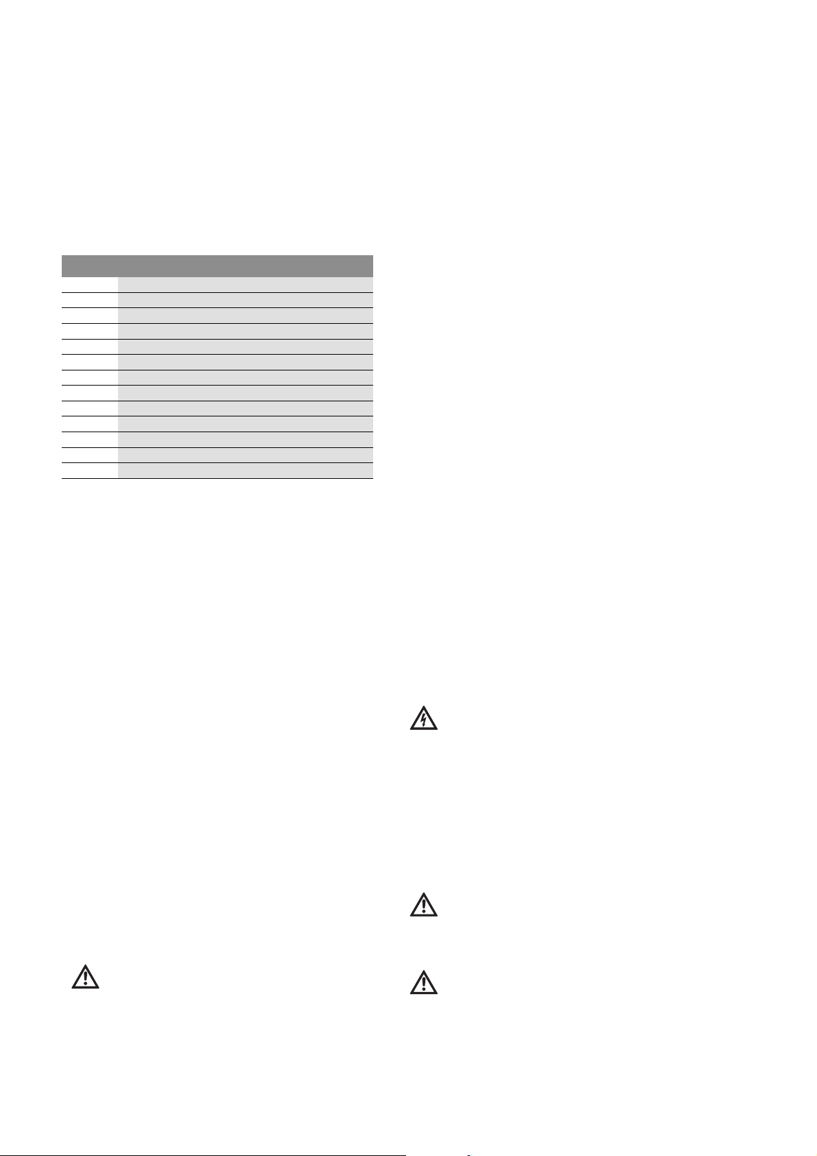
8.4 Füllstand des Motors prüfen und korrigieren
(Fig. 6)
Die Füllstandskontrolle und Korrektur der Motorfüllung muss von qualifizierten Personal durchgeführt werden. Beim Motor TWI4 darf das Nachfüllen nur durch den Hersteller durchgeführt werden.
• Motor horizontal legen mit Öffnung (C) nach
oben
• Prüfstift in die Bohrung (E) am Membrangehäuse
einführen und Membranstand (D) -siehe Tabelle
1- prüfen. Die Einkerbung am Prüfstift muss mit
der Außenkante der Bohrung übereinstimmen.
• Bei zu niedrigem Wasserstand, Filter (C) entfer-
nen (nur bei TWI6).
• Gefüllte Spritze am Ventil ansetzen und Wasser
in den Motor einspritzen.
• Zum Entlüften Ventil mit dem Prüfstift kurz ein-
drücken, bis Wasser blassenfrei austritt. Vorsicht Überdruck!
• So oft Wasser nach spritzen bis der Membranab-
stand (D) erreicht ist.
• Filter (C) wieder einsetzen.
8.3 Mediumstemperatur
Unterwassermotorpumpen dürfen bei Nennstrom
zwischen einer mind. Temperatur von 3°C und
einer max. Temperatur von 30°C betrieben werden. Um eine effektive Kühlung zu gewährleisten,
muss die Zirkulations-Fließgeschwindigkeit des
Kühlwassers über der Motor-Oberfläche wenigstens 10 cm/sec. bei 4“-Motoren und 16 cm/sec.
bei 6“-Motoren betragen.
Min. erforderlicher Volumenstrom zur Motorkühlung bis
30 °C Wassertemperatur
Innendurchmesser
Brunnenwand oder
Kühlmantelrohr
102mm (4“) 0,30 m³/h -127mm (5“) 1,60 m³/h -152mm (6“) 3,00 m³/h 2,10 m³/h
178mm (7“) 4,60 m³/h 6,00 m³/h
203mm (8“) 6,90 m³/h 10,30 m³/h
4“-Motor 6“-Motor
Motortyp Prüfmaß (D) Toleranz
4“ 10mm +/- 2mm
6“ (AISI 304 SS) 59mm +/- 2mm
6“ (AISI 316 SS) 19mm +/- 2mm
9Wartung
Wartungs- und Reparaturarbeiten nur durch
qualifiziertes Fachpersonal!
GEFAHR! Lebensgefahr!
Bei Arbeiten an elektrischen Geräten besteht
Lebensgefahr durch Stromschlag.
• Bei allen Wartungs- und Reparaturarbeiten ist
die Pumpe spannungsfrei zu schalten und gegen
unbefugtes Wiedereinschalten zu sichern.
• Schäden am Anschlusskabel sind grundsätzlich
nur durch einen qualifizierten Elektroinstallateur zu beheben.
HINWEIS: Keine besondere Wartung während des
Normalbetriebes erforderlich.
8 WILO AG 01/2008
Page 11

10 Störungen, Ursachen und Beseitigung
Störungsbeseitigung nur durch qualifiziertes
Fachpersonal durchführen lassen! Sicherheitshinweise unter Wartung beachten.
Störungen Ursachen Beseitigung
Pumpe läuft nicht an Falsche Spannung oder Spannungsabfall. Spannung beim Anlauf überprüfen, ein zu
geringer Kabeldurchschnitt kann zu einem
Spannungsabfall führen und die Pumpe
nicht anlaufen lassen.
Unterbrechung des Anschlusskabels. Widerstände der Phasen messen, Pumpe
heraufziehen und die Kabel kontrollieren.
Der Motorschutzschalter wurde ausgelöst. Schutzschaltereinstellung der Auslöse-
stromstärke prüfen und diese mit dem aufgenommenen Nennstrom vergleichen.
Pumpe startet zu oft. Startvorgänge reduzieren, Überhitzungsge-
fahr des Motors (ca. 1 min.).
Pumpe läuft fördert aber nicht Kein Wasser oder zu niedriger Wasserspiegel •Wasserniveau kontrollieren, mind. 0,20 m
über dem Ansaugstutzen gewährleisten.
• Pumpe entlüften.
Die Fördermenge ist zu niedrig. Der Ansaugfilter ist verstopft Pumpe heraufziehen und Filter säubern.
Falsche Drehrichtung (DM-Version) Zwei Phasen im Anschlusskasten tauschen.
Pumpe springt zu oft an.
Zu geringe Differenz zwischen Ein- und
Ausschaltdruck
Elektroden sind falsch installiert. Abstand zwischen den Elektroden so regeln,
Der Ausgleichsbehälter ist zu klein ausgelegt oder mit falschen Vordruck.
Differenz zwischen Ein- und Ausschaltdruck
erhöhen.
dass ein entsprechender Zeitraum zwischen
Stillstand und Betrieb der Pumpe gewährleistet ist.
Druck kontrollieren und regeln (Ein- und
Ausschalten). Vordruck des Behälters prüfen. Ausgleichsbehälter gegen einen Größeren tauschen oder durch einen Zusätzlichen
ergänzen.
Deutsch
Lässt sich die Betriebsstörung nicht beheben,
wenden Sie sich bitte an das Fachhandwerk oder
an die nächstgelegene Wilo Kundendienststelle
oder Vertretung.
11 Ersatzteile
Die Ersatzteil-Bestellung erfolgt über örtliche
Fachhandwerker und/oder den Wilo Kundendienst.
Um Rückfragen und Fehlbestellungen zu vermeiden, sind bei jeder Bestellung sämtliche Daten des
Typenschildes anzugeben.
Technische Änderungen vorbehalten!
Einbau- und Betriebsanleitung Wilo-Sub TWI4-6 9
Page 12
English
Installation and operating instructions
1 General
About this document
These installation and operating instructions are
an integral part of the product. They must be kept
readily available at the place where the product is
installed. Strict adherence to these instructions is
a precondition for the proper use and correct
operation of the product.
These installation and operating instructions correspond to the relevant version of the product and
the underlying safety standards valid at the time
of going to print.
2Safety
These operating instructions contain basic information which must be adhered to during installation and operation. For this reason, these operating instructions must, without fail, be read by the
service technician and the responsible operator
before installation and commissioning.
It is not only the general safety instructions listed
under the main point "safety" that must be adhered
to but also the special safety instructions with
danger symbols included under the following main
points.
2.1 Indication of instructions in the operating
instructions
Symbols:
General danger symbol
2.3 Danger in the event of non-observance of the
safety instructions
Non-observance of the safety instructions can
result in risk of injury to persons and damage to
pump/unit. Non-observance of the safety instructions can result in the loss of any claims to damages.
In detail, non-observance can, for example, result
in the following risks:
• Failure of important pump/unit functions
• Failure of required maintenance and repair procedures
• Danger to persons from electrical, mechanical and
bacteriological influences
• Property damage
2.4 Safety instructions for the operator
The existing directives for accident prevention
must be adhered to.
Danger from electrical current must be eliminated.
Local directives or general directives [e.g. IEC, VDE
etc.] and local power supply companies must be
adhered to.
2.5 Safety instructions for inspection and installation work
The operator must ensure that all inspection and
installation work is carried out by authorised and
qualified personnel, who are sufficiently informed
from their own detailed study of the operating
instructions.
Work to the pump/unit must only be carried out
when at a standstill.
Danger due to electrical voltage
NOTE
Signal words:
DANGER!
Acutely dangerous situation.
Non-observance results in death or the most
serious of injuries.
WARNING!
The user can suffer (serious) injuries. 'Warning'
implies that (serious) injury to persons is probable if this information is disregarded.
CAUTION!
There is a risk of damaging the pump/unit. 'Caution' implies that damage to the product is likely
if this information is disregarded.
NOTE: Useful information on handling the product. It draws attention to possible problems.
2.2 Personnel qualifications
The installation personnel must have the appropriate qualifications for this work.
2.6 Unauthorised modification and manufacture of
spare parts
Modifications to the pump/unit are only permissible after consultation with the manufacturer.
Original spare parts and accessories authorised by
the manufacturer ensure safety. The use of other
parts can nullify the liability from the results of
their usage.
2.7 Improper use
The operating safety of the supplied pump/unit is
only guaranteed for conventional use in accordance with Section 4 of the operating instructions.
The limit values must on no account fall under or
exceed those specified in the catalogue/data
sheet.
Installation and operating instructions
10 WILO AG 01/2008
Page 13

English
3 Transport and interim storage
Immediately after receiving the product:
• Check the product for damage in transit.
• If damage is found, the necessary procedures
involving the forwarding agent must be taken
within the specified period.
CAUTION! Danger of material damage!
The product may be damaged if it is not transported and stored correctly.
• For transport, the pump may only be lifted or
carried using the brackets intended for that purpose. The cable should never be used for lifting!
• The pump must be protected from moisture,
frost, heat, direct sunlight and mechanical damage during transport and interim storage.
• Firmly seal the pump pressure port to avoid contamination.
• During transport and interim storage observe
that the freezing point of the motor fluid
is -8 °C.
• Protect all electricity supply cables from kinking, damage and the penetration of moisture.
• Store the pump horizontally on a solid, level surface.
4Intended use
Wilo-Sub TWI submersible pumps are suitable for
pumping clean or slightly muddy water not containing long fibrous and abrasive components.
They are used for the following applications:
• for boreholes and cisterns,
• for pumping and distributing secondary hot water
for:
• domestic use (potable water supply)
• agriculture (irrigation, sprinkling)
• industry (pressure boosting etc.)
NOTE: Follow the locally applicable regulations for
the intended application.
The pumps are only installed flooded (immersed)
and can be installed horizontally and vertically
with cooling jacket pipe.
CAUTION! Danger of material damage! Pumping
materials which are not approved can lead to
damage to the product.
The pumps are not suitable for water containing
coarse contaminants such as fibres or flammable
liquids or for use in potentially explosive areas.
Correct use of the pump/installation also includes
following these instructions.
Any use over and beyond these is considered to be
incorrect use.
5 Product information
5.1 Type key (standard versions)
Example: WILO-Sub TWI 4.01-09-B EM
TWI Submersible pump
4 or 6 Minimal diameter:
4" and 6" borehole diameters
Pump diameter max. 98 mm for 4",
max. 152 mm for 6"
.01 Rated volume flow rate (m³/h)
-09
-B Pump generation
EM EM = Single-phase 1~230 V (50 Hz/60 Hz)
5.2 Technical data 50 Hz 60 Hz
Permissible fluid components:
Mains voltage: 1~230 V (4"),
Protection class: IP 68
Max. volume flow:
Max. delivery head: 4" = 320 m
Pressure port: 1¼", 1½", 2" for 4" hydraulics
Permissible fluid temperature range:
Max. submersion depth: 350 m
Max. switching frequency:
Number of pump stages
with soft starter
DM = Three-phase current 3~400 V (50 Hz),
3~480 V (60 Hz)
SD = Three-phase current, star-delta-start
(6" motors only)
max. sand content 50 g/m³
1~230 V (4")
3~400 V
(4", 6")
4" = 20 m³/h
6" = 78 m³/h
6" = 410 m
2½", 3" for 6" hydraulics
+3 to 30 °C
20/h
5.3 Scope of delivery (standard versions)
• Submersible motor pump
• Integrated non-return valve
• Connecting cable
• 1.5 m, 2.5 or 5 m long, detachable connecting
cable (4x1.5 mm²) for 4" motors or
• 4 m long connecting cable (4x4 mm²)
for 6" motors
• 230 V incl.:
• Switchbox with capacitor
• Integrated thermal motor protection
• On/Off switch
NOTE: Electrical connections are prepared at the
works.
• Installation and operating instructions
3~480 V
(4", 6")
4" = 25 m³/h
6" = 97 m³/h
4" = 340 m
6" = 520 m
5.4 Accessories (optional):
• Non-return valve on the borehole output
• Dry-running protection system: Float switch or
electrode
• WILO-ER switchgear (motor protection + waterlevel monitoring)
• Motor cable: as kit (incl. plug) or by the meter
(without plug)
Installation and operating instructions Wilo-Sub TWI4-6 11
Page 14
English
• Shrinkage hoses, or moulded sleeves (for motor
cable extension)
• Pressure vessel, tank
• WILO Fluidcontrol or WILO pressure switching ER
as Plug & Pump package (see separate installation
and operating instructions)
6 Description and function
6.1 Description of the pump (Fig. 4)
Pos. Description of component
1 Wilo-Sub pump DM version
2
3
4 Submersible electrode upper level
5
6
7
8
9
10 Pressure switch with pressure gauge
11
12
13 Non-return valve
Submersible electrode ground
Submersible electrode low water
Motor connecting cable
Dynamic level (pump in operation)
Static level (pump switched-off)
Switchbox (with dry-running protection system)
Mains supply
Pressure vessel/tank
Shut-off valve
Fully submersible, multistage submersible pump
with radial or semi-axial impellers. Coupling and
flange usable for motors with pumps, installation
dimensions in compliance with NEMA standards.
Built-in non-return valve in the pump head. Intermediate bearing in each stage, specially designed
to optimise the shaft bearings. Sturdy cable protection. Optimised hydraulics components for
achieving high efficiency. High resistance against
corrosion and abrasion, thanks to the qualities of
the stainless steel. Easy servicing, thanks to simple dismantling and installation characteristics of
the unit.
Corrosion-free single-phase or three-phase
motor with enamelled windings in hermetically
cast stator for direct starting with self-lubricating
bearings.
Motor cooling is achieved by transferring lost heat
to the fluid around the outer jacket of the motor.
The minimum flow speed of the fluid along the
motor is 10 cm/sec for a 4" motor is and is
16 cm/sec for a 6" motor.
6.2 Soft starter and frequency converter
As a general rule all motors can, within the limits
described in the following, be operated in combination with frequency converters and electronic
starters (soft starter).
CAUTION! Danger of material damage!
If these operating requirements are not met, the
service life of the pump will be reduced and can
destroy the motor!
6.2.1 Requirements when using electronic starters
(soft starter)
• The minimum required cooling flow speed must
be ensured at all duty points
(4" motors - 10 cm/sec, 6" motors - 16 cm/sec.)
• The current consumption must remain below the
nominal current (In) level during the entire operation (see name plate information).
• The ramp time for the start/stop procedures
between 0 and 30 Hz should be set to maximum
1 sec. The ramp time between 30 Hz and the
nominal frequency should be set to maximum
3sec.
• During start-up the voltage must be at least 55 %
of the nominal motor voltage.
• After normal operation has been reached, bridge
the electronic starter (soft starter) in order to
avoid power dissipation during operation.
6.2.2 Requirements when using frequency converters
• Permanent operation can only be ensured
between 30 Hz and 50 Hz (60 Hz).
• A time of min. 60 seconds between pump stop and
restart is recommended to cool the motor winding.
• Never exceed the nominal current (see name plate
information).
Maximum voltage peak: 1000 V
Maximum rate of voltage rise: 500 V/µs
• Additional filters are required if the control voltage required exceeds 400 V.
• During start-up the voltage must be at least 55 %
of the nominal motor voltage.
7Installation and electrical connection
DANGER! Risk of fatal injury!
Incorrect installation and incorrect electrical
connection can result in death.
• Installation and electrical work must only be
done by qualified personnel and in accordance
with applicable regulations!
• Accident prevention regulations must be
observed.
7.1 Installation
The pump can be installed vertically or horizontally with a cooling jacket pipe.
CAUTION! Danger of material damage!
Danger of damage due to incorrect handling.
Boreholes or pumping stations must be
arranged/designed according to generally valid
rules of technology.
CAUTION! Danger of material damage!
If installed in a > 4" or 6" borehole (see Fig. 4) or
if installed horizontally in a tank, it is imperative
that a suction shroud is fitted on the pump and
motor in order to ensure sufficient motor cool-
!
ing
12 WILO AG 01/2008
Page 15

English
• A 6" borehole is recommended for 4" pumps with
>9 m³/h rated volume flow rate, an 8" borehole is
recommended for 6" pumps with >30 m³/h rated
volume flow rate.
• The water inlet in a borehole or well must be adequate for the pump's flow capacity.
• The pump is lowered into place using a block and
tackle and tripod, heavy pumps are lowered into
place using a cable winch. Installation should take
place away from the incoming water or the filter
pipe.
• Never allow the pump to run dry. It must be
ensured that, even during dry periods, the water
level never falls below the top of the unit.
• A consistent inner pipe diameter of 4" (102 mm)
or 6" (152 mm) should be ensured in order to
guarantee that the pump can be lowered easily.
• The pump must never be lowered or pulled up
using the electrical cable.
• Electrical connection work and extension of the
motor cable must be performed before lowering
the pump.
• The pump must be installed at least 0.30 m above
the bottom of the well or the borehole (Fig. 4).
• The system name plate must be fitted near the
borehole to ensure access to the technical data of
the installation.
• The insulation resistance on the motor and cable
must be checked prior to lowering (and during
lowering in deep boreholes) (min. 2 M
• Depending on pump design, the pump can be
connected via a solid or flexible pipe, 1¼" to 3"
nominal diameter.
• The pump must be secured using a safety rope
when using flexible pipes. Use the steel eye bolts
Ω).
on the pump head for this. Solid pipes are preferred.
• It is recommended that you fit an additional nonreturn valve and shut-off valve on the borehole
output.
CAUTION! Danger of material damage!
When the water pressure is raised (>180 m Ws)
a non-return valve must be installed directly at
the pump outlet. The non-return valve must be
designed for a permissible operating pressure of
at least 20 bar!
• Observe the required motor cooling (see table
under "Fluid temperature")!
7.2 Electrical connection
DANGER! Risk of fatal injury!
A fatal shock may occur if the electrical connection is not made correctly.
Only allow the electrical connection to be made
by an electrician approved by the local electricity supplier and in accordance with the local regulations in force.
• The current type and voltage of the mains connection must correspond to the specifications on
the name plate.
• Use the connecting cable in accordance with
applicable standards/regulations and connect it
according to the switchgear or switch cabinet terminal diagram.
CAUTION! Danger of material damage!
The max. length of the cable is dependent on the
nominal current consumption of the motor and
the cable cross-section!
Refer to the table and check the lengths and
diameters of the cable before connection!
Diameter and max. lengths of the cable for direct start:
Motor version Motor Cable
kW 4 x 1.5 mm² 4 x 2.5 mm² 4 x 4 mm² 4 x 6 mm² 4 x 10 mm² 4 x 16 mm²
EM
1~ 50/60 Hz 230 V
DM
3~ 50 Hz 400 V
3~ 60 Hz 480 V
Cable weight (kg/m) 0.20 0.25 0.30 0.40 0.65 0.85
0.25100----------
0.3785144--------
0.55 64 107 140 -- -- --
0.75 49 83 110 165 -- --
1.10 32 54 80 120 195 --
1.50 25 35 60 95 153 245
2.20 17 25 45 65 102 163
0.37 661 1102 1764 2646 4411 7057
0.55 454 758 1213 1819 3032 4852
0.75 341 569 911 1367 2279 3647
1.10 245 409 655 983 1639 2623
1.50 179 299 478 718 1196 1915
2.20 121 202 324 486 811 1298
3.00 94 157 252 378 630 1008
3.70 76 128 204 307 512 819
4.00 70 118 188 283 472 755
5.50 52 87 140 210 351 562
7.50 39 65 104 157 261 418
Installation and operating instructions Wilo-Sub TWI4-6 13
Page 16
English
Diameters and max. lengths of the cable for direct start:
Motor version Motor Cable
kW 4 x 1.5 mm² 4 x 2.5 mm² 4 x 4 mm² 4 x 6 mm² 4 x 10 mm² 4 x 16 mm²
DM
3~ 50 Hz 400 V
3~ 60 Hz 480 V
Cable weight (kg/m) 0.20 0.25 0.30 0.40 0.65 0.85
Diameters and max. lengths of the cable (6" motors) for star-delta start:
Motor version Motor Cable
DM
3~ 50 Hz 400 V
3~ 60 Hz 480 V
Cable weight (kg/m) 0.20 0.25 0.30 0.40 0.65 0.85
9.30 32 54 87 130 217 348
11.00 -- 45 72 109 181 291
15.00 -- -- 54 81 135 216
18.50 -- -- 44 66 110 176
22.00 -- -- -- 55 92 147
30.00--------67108
37.00----------89
45.00----------73
kW 4 x 1.5 mm² 4 x 2.5 mm² 4 x 4 mm² 4 x 6 mm² 4 x 10 mm² 4 x 16 mm²
2.20 182 304 486 730 1217 1947
3.00 141 236 378 567 945 1513
3.70 115 192 307 461 768 1229
4.00 106 177 283 425 708 1133
5.50 79 131 210 316 527 843
7.50 58 98 157 235 392 628
9.30 48 81 130 195 326 522
11.00 40 68 109 163 272 436
15.00 30 50 81 121 203 324
18.50 24 41 66 99 165 264
22.00 -- 34 55 83 138 221
30.00 -- -- 40 60 101 162
37.00 -- -- -- 50 83 134
45.00--------68109
1~ 230 V (50 Hz, 60 Hz), EM version (Fig. 1)
Capacity Current consump-
tion 230V
kW A µF
0.37 3.2 16
0.55 4.3 20
0.75 5.3 30
1.10 7.8 40
1.50 9.9 50
2.20 14.9 75
3~400 V 50 Hz, 3~480 V 60 Hz, DM version
(Fig. 2 / 3)
Capacity Current consumption400/480 V
kW A
0.37 1.3
0.55 1.7
0.75 2.2
1.10 3.2
1.50 4.0
2.20 5.9
3.00 7.8
3.70 9.1
4.00 10.0
5.50 13.7
7.50 18.0
9.30 20.3
11.00 23.3
15.00 31.3
18.50 38.5
Operating capacitor
Connections
(wire identification)
Fig. 1 - 3
ablack
bblue / grey
cbrown
d green/yellow
CAUTION! Danger of material damage!
Connecting the motor incorrectly can damage it!
• Check the mains voltage
• Do not cut the cable between the switchbox and
pump. The switchbox contains the necessary
motor capacitors (EM versions only).
•Fit ground
• Motor protection is regulated by a thermal or
magnetic switch (fitted on EM ver sio n, t o be fitt ed
on the DM version)
8 Commissioning
8.1 Direction of rotation check (three-phase
motors only, the direction of rotation cannot be
confused on single-phase motors)
In order to define the correct direction of rotation,
it suffices to check the water pressure on the
pressure side of the pump that is running.
14 WILO AG 01/2008
Page 17
English
NOTE: If the pump is being operated with the
wrong direction of rotation, a reduction in the
volume flow occurs.
If the direction of rotation is incorrect, 2 phases of
the mains connection (in the switchbox or on the
contact maker) have to be changed.
8.2 Commissioning
CAUTION! Danger of material damage!
Danger of damage to the mechanical seal. Never
allow the pump to run dry, even for a short time.
• Check all electrical connections, the electrical
protection, and fuses once again.
• Check the current consumption intermittently
and compare with the values on the name plate.
Never exceed the motor nominal current (In)
permissible for the motor (see name plate)
• Check the voltage with the motor running.
Permissible tolerance: ± 10 %.
• Vent the pressure ports in order to avoid pressure
surge during start-up.
• Close the valves during initial commissioning to
minimise fluid hammers due to start-up and
briefly increased amounts of sand in the fluid (during initial use of the well).
• Do not start the pump more than 20 times an hour
(danger of overheating).
• Ensure that the pump is only operated within the
area printed in bold of the curve illustrated in the
catalogue. Under no circumstances operate the
pump to the right or left beyond the curve area
printed in bold.
• Never operate the pump for an extended period
with the valve closed.
8.3 Fluid temperature
Submersible pumps may, at nominal current, be
operated between min. 3 °C and max. 30 °C. In
order to guarantee effective cooling, the circulation flow velocity of the cooling water over the
surface of the motor must be at least 10 cm/sec.
for 4" motors and 16 cm/sec. for 6" motors.
Min. required volume flow for motor cooling up to a water
temperature of 30 °C
Inside diameter of the
side of the well or cooling
jacket pipe
102 mm (4") 0.30 m³/h -127 mm (5") 1.60 m³/h -152 mm (6") 3.00 m³/h 2.10 m³/h
178 mm (7") 4.60 m³/h 6.00 m³/h
203 mm (8") 6.90 m³/h 10.30 m³/h
4" motor 6" motor
In order to guarantee motor cooling at higher
temperatures, the flow rate must be reduced proportionally to the motor power (see table above)
NOTE: Do not operate the motors where the fluid
temperature exceeds 55 °C!
8.4 Checking and correcting the motor filling level
(Fig. 6)
The checking and correction of the filling level of
the motor fluid must be performed by qualified
personnel. The TWI4 motor may only be refilled by
the manufacturer.
• Lie the motor horizontally with opening (C) fac-
ing upwards
• Insert the pin gauge into the drilling (E) on the
diaphragm housing and check the diaphragm
level (D) -see table 1-. The notch on the pin
gauge must be level with the outer edge of the
drilling.
• If the water lever is too low, remove the filter (C)
(for TWI6 only).
• Place a filled syringe on the valve and inject
water into the motor.
• To vent the valve, briefly press the valve in with
the pin gauge until water that is free of bubbles
emerges. Caution over pressure!
• Continue filling with water until the diaphragm
level (D) has been reached.
• Re-insert the filter (C).
Type of motor Test dimen-
sion (D)
4" 10 mm +/- 2 mm
6" (AISI 304 SS) 59 mm +/- 2 mm
6" (AISI 316 SS) 19 mm +/- 2 mm
Tolerance
9Maintenance
Maintenance and repairs may only be carried out
by qualified experts!
DANGER! Risk of fatal injury!
When working on electrical equipment, there is
a risk of a fatal shock.
• The pump should be electrically isolated and
secured against unauthorised switch-on during
any maintenance or repair work.
• Any damage to the connecting cable should
always be rectified by a qualified electrician
only.
NOTE: No particular maintenance necessary during normal operation.
Fluid temperature
Water temperature
35 °C 95 %
40 °C 95 %
45 °C 90 %
50 °C 80 %
55 °C 70 %
Installation and operating instructions Wilo-Sub TWI4-6 15
Adjustment (%) of the nominal current from 0.37 kW to 5.5 kW
Page 18

English
10 Faults, causes and remedies
Only have faults remedied by qualified personnel!
Follow the safety instructions in Maintenance.
Faults Causes Remedy
Pump does not start. Incorrect voltage or voltage drop. Check voltage during start, a too narrow a
cable cross-section can lead to a voltage
drop and the pump does not start.
Breaks in the connecting cable. Measure the phase resistances, pull up the
pump and check the cable.
Pump running but does
not pump.
The volume flow is too low.
The pump starts too often.
The motor protection switch has been
triggered.
The pump starts too often. Reduce the number of starting procedures,
No water or the water level is too low • Check the water level, ensure there is
The suction filter is blocked Pull up the pump and clean the filter.
Incorrect direction of rotation (DM version) Change two phases in the connection box.
The difference between the switch-on and
switch-off pressure too low
Electrodes are installed incorrectly. Arrange the electrodes at a distance from
The diaphragm expansion tank is too small
or has incorrect supply pressure.
Check the protective switch setting of the
triggering current strength and compare it
with the nominal current being drawn.
danger of motor overheating
(approx. 1 min.).
min. 0.20 m water above the suction port.
• Vent pump.
Increase the difference between the
switch-on and switch-off pressure.
each other so adequate time between pump
standstill and pump operation is guaranteed.
Check and regulate the pressure (switch on
and off). Check the tank supply pressure.
Replace the diaphragm expansion tank with
a larger one or supplement with an additional diaphragm expansion tank.
If the operating fault cannot be remedied,
please consult a skilled professionals or the
nearest Wilo after-sales service or representative office.
11 Spare parts
Spare parts may be ordered via local professional
technicians and/or the Wilo after-sales service.
To avoid queries and incorrect orders, all data on
the name plate should be submitted for each
order.
Subject to change without prior notice!
16 WILO AG 01/2008
Page 19

Français
Notice de montage et de mise en service
1 Généralités
A propos de ce document
La notice de montage et de mise en service fait
partie intégrante du matériel et doit être disponible en permanence à proximité du produit. Le strict
respect de ses instructions est une condition
nécessaire à l'installation et à l'utilisation conformes du matériel.
La rédaction de la notice de montage et de mise en
service correspond à la version du matériel et aux
normes de sécurité en vigueur à la date de son
impression.
2Sécurité
Ce manuel renferme des consignes essentielles
qui doivent être respectées lors du montage et de
l'utilisation. Ainsi il est indispensable que l'installateur et l'opérateur du matériel en prennent connaissance avant de procéder au montage et à la
mise en service.
Les consignes à respecter ne sont pas uniquement
celles de sécurité générale de ce chapitre, mais
aussi celles de sécurité particulière qui figurent
dans les chapitres suivants, accompagnées d'un
symbole de danger.
2.1 Signalisation des consignes de la notice
Symboles :
Symbole général de danger
Consignes relatives aux risques électriques
2.3 Dangers en cas de non-observation des consignes
La non-observation des consignes de sécurité
peut constituer un danger pour les personnes,
la pompe ou l'installation. Elle peut également
entraîner la suspension de tout recours en garantie.
Plus précisément, les dangers peuvent être les
suivants :
• défaillance de fonctions importantes de la pompe
ou de l'installation
• défaillance du processus d'entretien et de réparation prescrit
• dangers pour les personnes par influences électriques, mécaniques ou bactériologiques
• dommages matériels
2.4 Consignes de sécurité pour l'utilisateur
Il convient d'observer les consignes en vue
d'exclure tout risque d'accident.
Il y a également lieu d'exclure tout danger lié à
l'énergie électrique. On se conformera aux dispositions de la réglementation locale ou générale
[IEC, VDE, etc.], ainsi qu'aux prescriptions de
l'entreprise qui fournit l'énergie électrique.
2.5 Consignes de sécurité pour les travaux d'inspection et de montage
L'utilisateur doit faire réaliser ces travaux par une
personne spécialisée qualifiée ayant pris connaissance du contenu de la notice.
Les travaux réalisés sur la pompe ou l'installation
ne doivent avoir lieu que si les appareillages correspondants sont à l'arrêt.
REMARQUE
Signaux :
DANGER !
Situation extrêmement dangereuse.
Le non-respect entraîne la mort ou des blessures graves.
AVERTISSEMENT !
L'utilisateur peut souffrir de blessures (graves).
« Avertissement » implique que des dommages
corporels (graves) sont vraisemblables lorsque
la consigne n'est pas respectée.
ATTENTION !
Il existe un risque d'endommager la pompe/installation. « Attention » signale une consigne
dont la non-observation peut engendrer un
dommage pour le matériel et son fonctionnement.
REMARQUE : Remarque utile sur le maniement du
produit. Elle fait remarquer les difficultés éventuelles.
2.2 Qualification du personnel
Il convient de veiller à la qualification du personnel
amené à réaliser le montage.
2.6 Modification du matériel et utilisation de pièces
détachées non agréées
Toute modification de la pompe ou de l'installation ne peut être effectuée que moyennant
l'autorisation préalable du fabricant. L'utilisation
de pièces détachées d'origine et d'accessoires
autorisés par le fabricant garantit la sécurité.
L'utilisation d'autres pièces dégage la société de
toute responsabilité.
2.7 Modes d'utilisation non autorisés
La sécurité de fonctionnement de la pompe/de
l'installation livrée n'est garantie que si les prescriptions précisées au chap. 4 de la notice de montage et de mise en service sont respectées. Les
valeurs indiquées dans le catalogue ou la fiche
technique ne doivent en aucun cas être dépassées, tant en maximum qu'en minimum.
Notice de montage et de mise en service
Notice de montage et de mise en service Wilo-Sub TWI4-6 17
Page 20

Français
3 Transport et entreposage
Dès la réception du produit :
• Contrôler le produit à la recherche de dommages
dus au transport,
• en cas de dommages dus au transport, faire les
démarches nécessaires dans les délais correspondants auprès du transporteur.
ATTENTION ! Risque de dommages matériels !
Un transport et un entreposage incorrects peuvent causer des dommages matériels au produit.
• La pompe peut seulement être accrochée/portée au niveau de l'étrier conçu à cet effet. Ne
jamais la porter au niveau du câble !
• La pompe doit être protégée de l'humidité, du
gel, de la chaleur, du rayonnement solaire direct
et d'un endommagement mécanique pendant le
transport et l'entreposage.
• La bride de refoulement de la pompe doit être
resserrée fermement lors du stockage afin
d'éviter des impuretés.
• Veiller à ce que le point de congélation du liquide
du moteur s'élève à -8 °C pendant le transport
et l'entreposage.
• Toutes les conduites d'alimentation en courant
doivent être protégées contre le pliage, les
endommagements et l'humidité.
• La pompe doit être stockée à l'horizontale sur un
sol dur et plan.
4 Applications
Les pompes submersibles Wilo-Sub TWI sont conçues pour le pompage de l'eau propre ou de l'eau
légèrement encrassée sans composant à longues
fibres ou abrasif.
Elles sont utilisées
• pour les forages et les citernes,
• pour le pompage et la distribution de l'eau chaude
sanitaire destinée :
• à l'usage domestique (distribution d'eau pota-
ble)
• à l'agriculture (irrigation, arrosage)
• à l'industrie (augmentation du niveau de pres-
sion etc.)
REMARQUE: Les directives locales doivent être
observées pour le cas d'utilisation respectif.
Les pompes sont exclusivement montées en état
submergé (immergé) et peuvent être installées à
l'horizontale avec le tube d'enveloppe de refroidissement et à la verticale.
ATTENTION ! Risque de dommages matériels !
Le pompage de matières non autorisées peut
endommager la pompe.
Les pompes ne sont pas conçues pour l'eau contenant des impuretés grossières comme les
fibres ou les liquides combustibles ni pour l'utilisation dans des domaines explosifs.
L'observation de ces instructions fait également
partie de l'utilisation conforme à l'usage prévu.
Toute autre utilisation est considérée comme non
conforme à l'usage prévu.
5 Informations produit
5.1 Dénomination (version standard)
Exemple : WILO-Sub TWI 4.01-09-B EM
TWI Pompe à moteur immergé
4 ou 6 Diamètre minimum :
Diamètres de forage 4" et 6"
Diamètre de pompe max. 98 mm avec 4",
max. 152 mm avec 6"
.01 Débit nominal (m³/h)
-09
-B Génération de pompe
EM EM = Courant monophasé 1~230 V (50 Hz/
5.2 Caractéristiques
Composants autorisés des
fluides véhiculés :
Tension d'alimentation : 1~230 V (4"),
Classe de protection : IP 68
Débit max. :
Hauteur manométrique
max. :
Bride de refoulement : 1¼", 1½", 2" avec
Plage de température autorisée du fluide véhiculé :
Profondeur d'immersion
max. :
Nombre de démarrages
max. :
Nombre d'étages de la pompe
60 Hz) avec démarrage en douceur
DM = Courant triphasé 3~400 V (50 Hz),
3~480 V (60 Hz)
SD = Courant triphasé, démarrage étoiletriangle (uniquement moteurs de 6")
50 Hz 60 Hz
techniques
Teneur max. en sable 50 g/m³
1~230 V (4")
3~400 V
(4", 6")
4" = 20 m³/h
6" = 78 m³/h
4" = 320 m
6" = 410 m
hydraulique de 4"
2½", 3" avec hydraulique
de 6"
+3 à 30 °C
350 m
20/h
5.3 Etendue de la fourniture (version standard)
• Pompe submersible
• Clapet anti-retour intégré
• Câble de raccordement
• Câble de raccordement amovible de 1,5 m, 2,5
ou 5 m (4x1,5 mm²) avec des moteurs de 4" ou
• Câble de raccordement de 4 m (4x4 mm²) avec
des moteurs de 6"
• 230 V y compris :
• Coffret de commande avec condensateur
• Protection moteur thermique intégrée
• Commutateur, coupe-circuit
REMARQUE : Les connexions électriques sont réalisées en usine.
• Notice de montage et de mise en service
3~480 V
(4", 6")
4" = 25 m³/h
6" = 97 m³/h
4" = 340 m
6" = 520 m
18 WILO AG 01/2008
Page 21

Français
5.4 Accessoires (en option) :
• Clapet anti-retour sur la sortie du forage
• Protection contre marche à sec : interrupteur à
flotteur ou électrode
• Appareillage électrique WILO-ER (protection
moteur + contrôle du niveau d'eau)
• Câble de moteur : comme kit (avec fiche) ou au
mètre (sans fiche)
• Gaines thermorétractables ou manchons à sceller
(pour prolonger le câble du moteur)
• Réservoir à pression, réservoir préliminaire
• Fluidcontrol WILO ou commutation à pression
WILO ER comme ensembles Plug & Pump (voir
notice de montage et de mise en service séparée)
6 Description et fonctionnement
6.1 Description de la pompe (Fig. 4)
Pos. Description des composants
1
2
3
4 Electrode immergée du niveau supérieur
5
6
7 Niveau statique (pompe hors service)
8
9 Alimentation réseau/alimentation électrique
10
11
12 Vanne d'arrêt
13
Pompe Wilo-Sub, version courant triphasé
Electrode immergée de la masse
Electrode immergée du manque d'eau
Câble de raccordement du moteur
Niveau dynamique (pompe en service)
Coffret de commande (avec protection contre
marche à sec)
Pressostat avec manomètre
Réservoir à pression/réservoir préliminaire
Clapet anti-retour
Pompe submersible multicellulaire à moteur
immergé avec roues radiales ou semi-axiales.
Accouplement et bride utilisables pour les
moteurs avec pompe, dimensions de montage en
accord avec les standards NEMA. Clapet antiretour monté dans la tête de pompe. Paliers intermédiaires à chaque étage, spécialement construits pour optimiser le logement de l'arbre.
Enveloppe protectrice de câbles solide. Composants hydrauliques optimisés permettant d'obtenir des rendements élevés. Résistance élevée à la
corrosion et à l'abrasion, qui est obtenue grâce aux
propriétés de l'acier inoxydable. Service aisé grâce
à des propriétés de démontage et de montage de
l'agrégat faciles.
Moteur monophasé ou triphasé résistant à la corrosion avec des bobinages enrobés d'une laque
dans un stator scellé hermétiquement pour un
démarrage direct avec des paliers autolubrifiants.
Le refroidissement du moteur est réalisé en transmettant la chaleur dissipée au fluide véhiculé
autour de l'enveloppe extérieure du moteur. La
vitesse d'écoulement minimum du fluide véhiculé
le long du moteur s'élève, avec un moteur de 4", à
10 cm/sec et, avec un moteur de 6", à 16 cm/sec.
6.2 Démarrage en douceur et convertisseur
de fréquence
En général, tous les moteurs peuvent être utilisés
en combinaison avec les convertisseurs de fréquence et les démarreurs électroniques (démarrage en douceur) au sein des limites décrites ciaprès.
ATTENTION ! Risque de dommages matériels !
Si les conditions d'utilisation ne sont pas remplies, la durée de vie de la pompe est réduite et
le moteur risque d'être détruit !
6.2.1 Conditions d'utilisation des démarreurs électroniques (démarrage en douceur)
• La vitesse d'écoulement minimum nécessaire de
refroidissement doit être garantie sur tous les
points de fonctionnement (moteurs de 4" 10 cm/sec, moteurs de 6" - 16 cm/sec.)
• L'intensité absorbée doit se trouver, pendant le
fonctionnement complet, au-dessous du courant
nominal (In) (voir indication de la plaque signalétique).
• Le temps de rampe pour les procédures de démarrage/d'arrêt entre 0 et 30 Hz doit être réglé sur
1 sec. maximum. Le temps de rampe entre 30 Hz
et la fréquence nominale doit être réglé sur 3 sec.
maximum.
• La tension au démarrage doit s'élever à au moins
55 % de la tension nominale du moteur.
• Pour éviter des pertes en puissance pendant le
fonctionnement, ponter le démarreur électronique (démarrage en douceur) après avoir atteint le
fonctionnement normal.
6.2.2 Conditions d'utilisation du convertisseur
de fréquence
• Le fonctionnement continu peut seulement être
garanti entre 30 Hz et 50 Hz (60 Hz).
• Pour le refroidissement du bobinage du moteur,
un laps de temps d'au moins 60 sec. doit être respecté entre l'arrêt de la pompe et le redémarrage.
• Ne jamais dépasser le courant nominal (voir indication de la plaque signalétique).
Pic maximum de tension : 1000 V
Vitesse maximum de montée de la tension :
500 V/µs
• Des filtres supplémentaires sont nécessaires si la
tension de commande requise dépasse 400 V.
• La tension au démarrage doit s'élever à au moins
55 % de la tension nominale du moteur.
7 Montage et raccordement électrique
DANGER ! Danger de mort !
Un montage et un raccordement électrique non
conformes peuvent avoir des conséquences
mortelles.
• Ne faire effectuer le montage et le raccordement électrique que par du personnel spécialisé
et conformément aux prescriptions en vigueur !
• Observer les consignes de prévention des accidents !
Notice de montage et de mise en service Wilo-Sub TWI4-6 19
Page 22

Français
7.1 Montage
La pompe peut être montée à la verticale ou à
l'horizontale avec un tube d'enveloppe de refroidissement.
ATTENTION ! Risque de dommages matériels !
Risque de détérioration dû à une manipulation
non conforme. Les forages ou stations de pompage doivent être construits et dimensionnés
conformément aux règles techniques généralement en vigueur.
ATTENTION ! Risque de dommages matériels !
Dans le cas d'un montage dans un forage > 4" ou
6" (voir Fig. 4) ou dans un réservoir préliminaire
avec montage horizontal, une enveloppe de guidage de l'eau doit impérativement être mise en
place autour de la pompe et du moteur afin de
garantir un refroidissement suffisant du
moteur!
• Pour les pompes de 4" avec un débit nominal
>9 m³/h, un forage de 6" est recommandé, pour
les pompes de 6" d'un débit nominal >30 m³/h, un
forage de 8" est recommandé.
• L'écoulement d'eau dans le forage ou le puits doit
être suffisant pour le débit de la pompe.
• La pompe est descendue à l'aide d'une moufle
avec chaîne et d'un trépied, de lourdes pompes à
l'aide de treuils pour câble. Le montage devrait
être réalisé en dehors de l'arrivée de l'eau ou du
tube de filtrage.
• La pompe ne doit jamais fonctionner à sec. Il faut
s'assurer à cet effet que, même en périodes de
sécheresse, le niveau de l'eau ne descend pas audessous du bord supérieur du groupe.
• Afin de pouvoir garantir une descente libre de la
pompe, un diamètre intérieur de tube constant de
4" (102 mm) ou 6" (152 mm) doit être assuré.
• La pompe ne doit jamais être descendue ou
remontée avec le câble électrique.
• Le raccordement électrique et le prolongement du
câble du moteur doivent être réalisés avant la descente de la pompe.
• La pompe doit être installée à 0,30 m au-dessus
du sol du puits ou du forage (Fig. 4).
• La plaque signalétique de l'installation doit être
appliquée à proximité du forage pour pouvoir permettre l'accès aux caractéristiques techniques de
l'installation.
• Avant la descente (et pendant l'abaissement dans
les forages profonds), la résistance d'isolement du
moteur et du câble doit être contrôlée (au moins
2fois
Ω).
• La pompe peut être raccordée au moyen d'une
tuyauterie fixe ou flexible de diamètre nominal
1¼" à 3", selon le modèle de pompe.
• En cas d'utilisation de tuyauteries flexibles, la
pompe doit être maintenue par un câble de sécurité. Les œillets d'acier de la tête de pompe doivent
être utilisés à cet effet. Les tuyauteries fixes doivent être utilisées de préférence.
• Il est recommandé de prévoir sur la sortie du
forage un clapet anti-retour supplémentaire ainsi
qu'une vanne d'arrêt.
ATTENTION ! Risque de dommages matériels !
En cas de pression de l'eau élevée (>180 m de
colonne d'eau), un clapet anti-retour doit être
installé directement sur la sortie de la pompe.
Le clapet anti-retour doit être conçu pour une
pression de service autorisée de 20 bar au
moins !
• Veiller à un refroidissement suffisant du moteur
(voir tableau au point « Température du fluide ») !
7.2 Raccordement électrique
DANGER ! Danger de mort !
En cas de raccordement électrique non conforme, il y a un danger de mort par choc électrique.
Ne faire effectuer le raccordement électrique
que par des installateurs électriques agréés par
le fournisseur d'énergie électrique local et conformément aux prescriptions locales en vigueur.
• Le courant et la tension de l'alimentation réseau
doivent coïncider avec les indications de la plaque
signalétique.
• Utiliser le câble de raccordement conformément
aux normes/prescriptions en vigueur et le raccorder conformément au schéma des connexions
serrées de l'appareillage électrique ou de l'armoire
de commande.
ATTENTION ! Risque de dommages matériels !
La longueur max. du câble dépend de l'intensité
absorbée nominale du moteur et de la section
transversale du câble !
Avant de raccorder le câble, contrôler sa longueur et son diamètre à l'appui du tableau !
20 WILO AG 01/2008
Page 23

Diamètres et longueurs max. du câble en cas de démarrage direct :
Modèle de moteur Mo-
Câble
teur
kW 4 x 1,5 mm² 4 x 2,5 mm² 4 x 4 mm² 4 x 6 mm² 4 x 10 mm² 4 x 16 mm²
EM
1~ 50/60 Hz230 V
0,25100---------0,3785144-------0,55 64 107 140 -- -- -0,75 49 83 110 165 -- -1,10 32 54 80 120 195 -1,50 25 35 60 95 153 245
2,20 17 25 45 65 102 163
DM
3~ 50 Hz 400 V
3~ 60 Hz 480 V
0,37 661 1102 1764 2646 4411 7057
0,55 454 758 1213 1819 3032 4852
0,75 341 569 911 1367 2279 3647
1,10 245 409 655 983 1639 2623
1,50 179 299 478 718 1196 1915
2,20 121 202 324 486 811 1298
3,00 94 157 252 378 630 1008
3,70 76 128 204 307 512 819
4,00 70 118 188 283 472 755
5,50 52 87 140 210 351 562
7,50 39 65 104 157 261 418
Poids du câble (kg/m) 0,20 0,25 0,30 0,40 0,65 0,85
Français
Diamètres et longueurs max. du câble en cas de démarrage direct :
Modèle de moteur Mo-
Câble
teur
kW 4 x 1,5 mm² 4 x 2,5 mm² 4 x 4 mm² 4 x 6 mm² 4 x 10 mm² 4 x 16 mm²
DM
3~ 50 Hz 400 V
3~ 60 Hz 480 V
9,30 32 54 87 130 217 348
11,00 -- 45 72 109 181 291
15,00 -- -- 54 81 135 216
18,50 -- -- 44 66 110 176
22,00 -- -- -- 55 92 147
30,00--------67108
37,00----------89
45,00----------73
Poids du câble (kg/m) 0,20 0,25 0,30 0,40 0,65 0,85
Diamètres et longueurs max. du câble (moteurs de 6") avec démarrage étoile-triangle :
Modèle de moteur Mo-
Câble
teur
kW 4 x 1,5 mm² 4 x 2,5 mm² 4 x 4 mm² 4 x 6 mm² 4 x 10 mm² 4 x 16 mm²
DM
3~ 50 Hz 400 V
3~ 60 Hz 480 V
2,20 182 304 486 730 1217 1947
3,00 141 236 378 567 945 1513
3,70 115 192 307 461 768 1229
4,00 106 177 283 425 708 1133
5,50 79 131 210 316 527 843
7,50 58 98 157 235 392 628
9,30 48 81 130 195 326 522
11,00 40 68 109 163 272 436
15,00 30 50 81 121 203 324
18,50 24 41 66 99 165 264
22,00 -- 34 55 83 138 221
30,00 -- -- 40 60 101 162
37,00 -- -- -- 50 83 134
45,00--------68109
Poids du câble (kg/m) 0,20 0,25 0,30 0,40 0,65 0,85
Notice de montage et de mise en service Wilo-Sub TWI4-6 21
Page 24

Français
1~ 230 V (50 Hz, 60 Hz), exécution EM (Fig. 1)
Performances
kW A µF
0,37 3,2 16
0,55 4,3 20
0,75 5,3 30
1,10 7,8 40
1,50 9,9 50
2,20 14,9 75
Performances Intensité absorbée 400/480 V
kW A
0,37 1,3
0,55 1,7
0,75 2,2
1,10 3,2
1,50 4,0
2,20 5,9
3,00 7,8
3,70 9,1
4,00 10,0
5,50 13,7
7,50 18,0
9,30 20,3
11,00 23,3
15,00 31,3
18,50 38,5
Fig. 1 - 3
anoir
bbleu/gris
cmarron
dvert/jaune
Intensité absorbée
230V
3~400 V 50 Hz, 3~480 V 60 Hz,
exécution DM (Fig. 2 / 3)
Raccordements
(identification des brins)
ATTENTION ! Risque de dommages matériels !
En cas de raccordement incorrect du moteur, il
risque d'être endommagé !
•Contrôler la tension d'alimentation
• Ne pas sectionner le câble qui relie le coffret de
commande à la pompe. Le coffret de commande
contient les condensateurs nécessaires du moteur
(uniquement pour les exécutions EM).
• Prévoir la mise à la terre
• La protection moteur est réalisée grâce à un coupleur thermique ou magnétique (disponible sur
l'exécution EM, à prévoir sur l'exécution DM)
Condensateur de
service
8 Mise en service
8.1 Le contrôle du sens de rotation (uniquement
pour les moteurs triphasés ; pour les moteurs
monophasés, pas de confusion du sens de rotation possible)
Afin de déterminer le sens de rotation correct, il
suffit de contrôler la pression de l'eau sur le côté
de la pression de la pompe en marche.
REMARQUE : Si la pompe est exploitée avec un
sens de rotation incorrect, une réduction du débit
intervient.
En cas de sens de rotation incorrect, 2 phases de
l'alimentation réseau (dans le coffret de commande ou sur le contacteur) doivent être échangées.
8.2 Mise en service
ATTENTION ! Risque de dommages matériels !
Risque d'endommagement de la garniture
mécanique. Ne jamais faire fonctionner la
pompe à sec même brièvement !
• Contrôler une fois encore tous les raccordements
électriques, la protection électrique et les fusibles.
• Contrôler l'intensité absorbée phase après phase
et la comparer avec les valeurs de la plaque signalétique.
Ne jamais dépasser le courant nominal autorisé
pour le moteur (In) (voir plaque signalétique)
• Contrôler la tension avec le moteur en marche.
Tolérance admise : ± 10 %.
• Ventiler la bride de refoulement afin d'éviter les
coups de bélier lors du démarrage.
• Lors de la première mise en service, fermer les
soupapes. De cette façon, les coups de bélier dus
au démarrage et les quantités de sable brièvement
élevées dans le fluide véhiculé sont minimisés (lors
de la première utilisation du puits).
• Ne pas démarrer la pompe plus de 20 fois par
heure (risque de surchauffe).
• S'assurer que la pompe fonctionne seulement au
sein du domaine imprimé en gras de la courbe
caractéristique du catalogue. En aucun cas ne faire
fonctionner la pompe à droite ou à gauche en
dehors du domaine imprimé en gras de la courbe
caractéristique.
• Ne jamais faire fonctionner la pompe pour un
temps prolongé avec la soupape fermée.
8.3 Température du liquide
Les pompes submersibles peuvent être exploitées
en courant nominal entre une température min. de
3 °C et une température max. de 30 °C. Pour assurer un refroidissement efficace, la vitesse d'écoulement de circulation de l'eau de refroidissement
au-dessus de la surface du moteur doit s'élever
à au moins 10 cm/sec. avec des moteurs de 4" et
à 16 cm/sec. avec des moteurs de 6".
Débit min. requis pour le refroidissement du moteur avec
une température d'eau max. de 30 °C
Diamètre intérieur de la
paroi du puits ou du
tuyau de l'enveloppe de
refroidissement
102 mm (4") 0,30 m³/h -127 mm (5") 1,60 m³/h -152 mm (6") 3,00 m³/h 2,10 m³/h
178 mm (7") 4,60 m³/h 6,00 m³/h
203 mm (8") 6,90 m³/h 10,30 m³/h
Moteur de 4" Moteur de 6"
22 WILO AG 01/2008
Page 25

Français
Température du liquide
Température d'eau Réglage (%) du courant nominal
de 0,37 kW à 5,5 kW
35 °C 95 %
40 °C 95 %
45 °C 90 %
50 °C 80 %
55 °C 70 %
Afin de garantir le refroidissement du moteur à des
températures élevées, le débit doit être réduit
proportionnellement à la puissance du moteur
(voir tableau précédent)
REMARQUE : Ne pas faire fonctionner les moteurs
à des températures de fluide supérieures à 55 °C !
8.4 Contrôler et corriger le niveau de remplissage
du moteur (Fig. 6)
Le contrôle du niveau de remplissage et la correction du remplissage du moteur doivent être réalisés par un personnel qualifié. L'appoint en liquide
du moteur TWI4 peut seulement être réalisé par le
fabricant.
• Placer le moteur à l'horizontale avec l'ouverture
(C) vers le haut
• Insérer la broche de contrôle dans l'alésage (E)
du boîtier de la membrane et contrôler le niveau
de la membrane (D) -voir tableau 1-. L'encoche
sur la broche de contrôle doit coïncider avec le
bord extérieur de l'alésage.
• Retirer le filtre (C) en cas de niveau d'eau trop
bas (uniquement pour TWI6).
• Mettre la seringue remplie en place sur la sou-
pape et injecter l'eau dans le moteur.
• Pour la ventilation, enfoncer brièvement la sou-
pape avec la broche de contrôle jusqu'à ce que
l'eau sorte sans bulle. Attention surpression !
• Injecter de l'eau jusqu'à ce que l'écart de la
membrane (D) avec la broche soit atteint.
• Remettre le filtre (C) en place.
9Entretien
Seul le personnel qualifié est habilité à effectuer
les travaux d'entretien et de réparation !
DANGER ! Danger de mort !
En cas de travaux sur les appareils électriques, il
y a un danger de mort par choc électrique.
• Pour tous les travaux d'entretien et de réparation, il faut mettre la pompe hors tension et la
protéger contre toute remise en marche intempestive.
• Seul un installateur électrique qualifié est habilité à réparer les câbles de raccordement
endommagés.
REMARQUE : Pas d'entretien particulier nécessaire
pendant le fonctionnement normal.
Type de moteur Mesure de
contrôle (D)
4" 10 mm +/- 2 mm
6" (AISI 304 SS) 59 mm +/- 2 mm
6" (AISI 316 SS) 19 mm +/- 2 mm
Tolérance
Notice de montage et de mise en service Wilo-Sub TWI4-6 23
Page 26

Français
10 Pannes, causes et remèdes
Ne faire effectuer le dépannage que par du personnel qualifié ! Observer les consignes de sécurité sous Entretien.
Pannes Causes Remèdes
La pompe ne démarre pas Tension incorrecte ou chute de tension. Contrôler la tension lors du démarrage, un
diamètre de câble trop petit peut conduire à
une chute de tension et la pompe ne peut
alors plus démarrer.
Rupture du câble de raccordement. Mesurer les résistances des phases, remon-
ter la pompe et contrôler les câbles.
La protection thermique moteur s'est
déclenchée.
La pompe démarre trop souvent. Réduire les procédures de démarrage, dan-
La pompe fonctionne mais ne
pompe pas
Le débit est trop bas. Le filtre d'aspiration est bouché Remonter la pompe et nettoyer le filtre.
La pompe démarre trop souvent.
Pas d'eau ou niveau d'eau trop bas • Contrôler le niveau d'eau et garantir un
Sens de rotation incorrect (exécution DM) Echanger deux phases dans la boîte de
Différence entre la pression d'amorçage et
celle d'arrêt trop basse
Les électrodes sont montées incorrectement.
Le bac d'expansion à membrane est dimensionné trop petit ou avec une pression d'alimentation incorrecte.
Contrôler le réglage du disjoncteur de pro-
tection de l'intensité du courant de déclen-
chement et le comparer avec l'intensité
nominale absorbée.
ger de surchauffe du moteur (1 min. env.).
niveau min. de 0,20 m au-dessus de l'orifice d'aspiration.
• Ventiler la pompe.
branchement.
Augmenter la différence entre la pression
d'amorçage et celle d'arrêt
Régler la distance entre les électrodes de
façon à ce qu'une durée correspondante
entre l'arrêt et le fonctionnement de la
pompe soit garantie.
Contrôler et régler la pression (mise en mar-
che et à l'arrêt). Contrôler la pression d'ali-
mentation du bac. Remplacer le bac
d'expansion à membrane contre un plus
grand ou le compléter par un bac supplé-
mentaire.
S'il s'avère impossible de supprimer la panne,
s'adresser à un artisan spécialisé, au service
après-vente ou à l'agence la plus proche Wilo.
11 Pièces de rechange
La commande de pièces de rechange s'effectue
par l'intermédiaire des artisans spécialisés locaux
et/ou du service après-vente Wilo.
Afin d'éviter toutes questions ou commandes
erronées, veuillez indiquer toutes les données de
la plaque signalétique à chaque commande.
Sous réserves de modifications techniques !
24 WILO AG 01/2008
Page 27

Español
1 Generalidades
Acerca de este documento
Las instrucciones de instalación y funcionamiento
forman parte del producto y, por lo tanto, deben
estar disponibles cerca del mismo en todo
momento. Es condición indispensable respetar
estas instrucciones para poder hacer un correcto
uso del producto de acuerdo con las normativas
vigentes.
Las instrucciones de instalación y funcionamiento
se aplican al modelo actual del producto y a las
versiones de las normativas técnicas de seguridad
aplicables en el momento de su publicación.
2Seguridad
Este manual contiene indicaciones básicas que
deberán tenerse en cuenta durante la instalación y
uso del aparato. Por este motivo, el instalador y el
operador responsables deberán leerlo antes de
montar y poner en marcha el aparato.
No sólo es preciso respetar las instrucciones
generales de seguridad incluidas en este apartado,
también se deben respetar las instrucciones especiales de los apartados siguientes que van precedidas por símbolos de peligro.
2.1 Identificación de los símbolos e indicaciones
utilizados en este manual
Símbolos:
Símbolo de peligro general
Peligro por tensión eléctrica
INDICACIÓN
Palabras identificativas:
¡PELIGRO!
Situación extremadamente peligrosa.
Si no se tienen en cuenta las instrucciones
siguientes, se corre el peligro de sufrir lesiones
graves o incluso la muerte.
¡ADVERTENCIA!
El usuario podría sufrir lesiones que podrían
incluso ser de cierta gravedad. “Advertencia”
implica que es probable que se produzcan daños
personales si no se respetan las indicaciones.
¡ATENCIÓN!
Existe el riesgo de que la bomba o el sistema
sufran daños.
“Atención” implica que el producto puede resultar dañado si no se respetan las indicaciones.
INDICACIÓN: Información de utilidad para el
manejo del producto. También puede indicar la
presencia de posibles problemas.
2.3 Riesgos en caso de inobservancia de las instrucciones de seguridad
Si no se siguen las instrucciones de seguridad,
podrían producirse lesiones personales, así como
daños en la bomba o el sistema. La no observación
de dichas instrucciones puede anular cualquier
derecho a reclamaciones por los daños sufridos.
Si no se siguen las instrucciones, se pueden producir, entre otros, los siguientes daños:
• Fallos en funciones importantes de la bomba o el
sistema,
• Fallos en los procedimientos obligatorios de mantenimiento y reparación,
• Lesiones personales debidas a causas eléctricas,
mecánicas o bacteriológicas,
• Daños materiales.
2.4 Instrucciones de seguridad para el operador
Deberán cumplirse las normativas vigentes de
prevención de accidentes.
Es preciso evitar la posibilidad de que se produzcan peligros debidos a la energía eléctrica. Así
pues, deberán respetarse las indicaciones de las
normativas locales o generales (p. ej. IEC, UNE,
etc.) y de las compañías eléctricas.
2.5 Instrucciones de seguridad para la inspección y
el montaje
El operador deberá asegurarse de que todas las
tareas de inspección y montaje son efectuadas por
personal autorizado y cualificado, y de que dicho
personal ha consultado detenidamente el manual
para obtener la suficiente información necesaria.
Las tareas relacionadas con la bomba o el sistema
deberán realizarse únicamente con el sistema
desconectado.
2.6 Modificaciones del material y utilización de
repuestos no autorizados
Sólo se permite modificar la bomba o el sistema
con la aprobación con el fabricante. El uso de
repuestos originales y accesorios autorizados por
el fabricante garantiza la seguridad del producto.
No se garantiza un funcionamiento correcto si se
utilizan piezas de otro tipo.
2.7 Modos de utilización no permitidos
La fiabilidad de la bomba o el sistema suministrados sólo se puede garantizar si se respetan las instrucciones de uso del apartado 4 de este manual.
Asimismo, los valores límite indicados en el catálogo o ficha técnica no deberán sobrepasarse por
exceso ni por defecto.
Instrucciones de instalación y funcionamiento
2.2 Cualificación del personal
El personal de montaje deberá estar debidamente
cualificado para realizar las tareas asignadas.
Instrucciones de instalación y funcionamiento Wilo-Sub TWI4-6 25
Page 28

Español
3 Transporte y almacenamiento
Inmediatamente después de la recepción del producto:
• Compruebe si el producto ha sufrido daños
durante el transporte.
• Si el producto ha sufrido daños, tome las medidas
necesarias con respecto a la agencia de transportes respetando los plazos establecidos para estos
casos.
¡PRECAUCIÓN! Riesgo de que se produzcan
daños materiales.
Si el transporte y el almacenamiento transitorio
no tienen lugar en las condiciones adecuadas, el
producto puede sufrir daños.
• Para transportar la bomba, ésta debe colgarse o
llevarse únicamente en el estribo provisto para
tal fin. ¡Nunca del cable!
• La bomba debe protegerse durante el transporte
y el almacenamiento transitorio frente a la
humedad, las heladas, el calor, la radiación solar
directa o posibles daños mecánicos.
• La boca de impulsión de la bomba debe cerrarse
bien durante su almacenamiento para evitar que
se ensucie.
• Durante el transporte y almacenamiento transitorio, debe tenerse en cuenta que el punto de
congelación del líquido del motor es -8 °C.
• Es importante evitar que los cables de alimentación se doblen, sufran algún desperfecto o
penetre en ellos la humedad.
• La bomba debe almacenarse en posición horizontal sobre un suelo firme y nivelado.
4 Aplicaciones
Las bombas sumergibles Wilo-Sub TWI son aptas
para bombear agua limpia o ligeramente sucia sin
componentes abrasivos o de fibra larga.
Las bombas encuentran aplicación en:
• perforaciones y cisternas,
• bombas y distribución de agua caliente sanitaria
para:
• uso doméstico (abastecimiento de agua potable)
• uso agrícola (aspersión, riego)
• uso industrial (equipos de presión, etc.)
INDICACIÓN: En cada uno de estos casos deben
observarse las normativas locales correspondientes.
Las bombas únicamente se montan inundadas
(sumergidas) y se pueden instalar tanto vertical
como horizontalmente con camisa de refrigeración.
¡PRECAUCIÓN! Riesgo de que se produzcan
daños materiales. El uso de sustancias no permitidas puede ocasionar daños materiales en la
bomba.
Las bombas no son idóneas para trabajar con
agua con impurezas como fibras o líquidos inflamables, ni para ser utilizadas en áreas con peligro de explosión.
Para ceñirse al uso previsto es imprescindible
observar las presentes instrucciones.
Todo uso que no figure en las mismas se considerará como no previsto.
5 Especificaciones del producto
5.1 Claves del tipo (variante estándar)
WILO-Sub TWI 4.01-09-B EM
Ejemplo:
TWI Bomba sumergible
4 ó 6 Diámetro mínimo:
Diámetro de perforación 4" y 6"
Diámetro máx. de la bomba 98 mm con 4",
máx. 152 mm con 6"
.01 Caudal nominal (m³/h)
-09
-B Generación de bombas
EM EM = Corriente monofásica 1~230 V (50 Hz/
5.2 Datos técnicos 50 Hz 60 Hz
Componentes admisibles del
medio de impulsión:
Tensión de red: 1~230 V (4"),
Tipo de protección: IP 68
Caudal máx.:
Altura de impulsión máx.: 4" = 320 m
Boca de impulsión: 1¼", 1½", 2"
Rango de temperaturas permitido del medio de impulsión:
Profundidad de inmersión
máx.:
Frecuencia de arranque máx.:
Número de etapas de la bomba
60 Hz) con arranque suave
DM = Corriente trifásica 3~400 V (50 Hz),
3~480 V (60 Hz)
SD = Corriente trifásica, arranque estrellatriángulo (sólo motores de 6")
Contenido de arena máx.
50 g/m³
1~230 V (4")
3~400 V
(4", 6")
4" = 20 m³/h
6" = 78 m³/h
6" = 410 m
con hidráulica 4"
2½", 3" con hidráulica 6"
+3 a 30 °C
350 m
20/h
5.3 Suministro (variante estándar)
• Bomba sumergible
• Válvula antirretorno integrada
• Cable de conexión
• Cable de conexión desconectable de 1,5 m, 2,5
ó 5 m de largo (4x1,5 mm²) para motores de 4" o
bien
• Cable de conexión de 4 m de largo (4x4 mm²)
para motores de 6"
• 230 V incl.:
• Caja de bornes con condensador
• Protección térmica de motor integrada
• Interruptor ON/OFF
INDICACIÓN: Las conexiones eléctricas se realizan
en fábrica.
•Instrucciones de instalación y funcionamiento
3~480 V
(4", 6")
4" = 25 m³/h
6" = 97 m³/h
4" = 340 m
6" = 520 m
26 WILO AG 01/2008
Page 29

Español
5.4 Accesorios (opcional):
• Clapeta antirretorno a la salida de la perforación
• Protección contra marcha en seco: interruptor de
flotador o electrodo
• Cuadro de conmutación WILO-ER (protección de
motor + control del nivel del agua)
• Cable del motor: como kit (incl. enchufe) o por
metro (sin enchufe)
• Tubo termorretráctil o manguitos (para alargar el
cable del motor)
• Depósito de presión, aljibe
• WILO-Fluidcontrol o sistema de conmutación por
presión de WILO ER como paquete Plug & Pump
(véase las instrucciones de instalación y funcionamiento aparte)
6 Descripción y funcionamiento
6.1 Descripción de la bomba (Fig. 4)
Pos. Descripción de componente
1 Bomba Wilo-Sub en modelo de motor trifásico
2
3
4 Electrodo sumergible nivel superior
5
6
7 Nivel estático (bomba desconectada)
8
9 Alimentación eléctrica/suministro de corriente
10
11
12 Válvula de cierre
13
Electrodo sumergible medidas
Electrodo sumergible falta de agua
Cable de conexión del motor
Nivel dinámico (bomba en funcionamiento)
Caja de bornes (con protección contra marcha en
seco)
Presostato con manómetro
Depósito de presión/aljibe
Válvula antirretorno
Bomba sumergible inundable multietapa con
rodetes radiales o semiaxiales. Acoplamiento y
brida utilizables para motores con bomba, dimensiones de montaje de acuerdo con los estándares
NEMA. Válvula antirretorno integrada en el cabezal de la bomba. Cojinetes intermedios en cada
etapa, diseñados especialmente para optimizar la
suspensión del eje. Robusta protección del cable.
Los componentes del grupo hidráulico han sido
optimizados para obtener un alto rendimiento.
Alta resistencia contra corrosión y abrasión gracias
a las propiedades del acero inoxidable. Fácil reparación y mantenimiento gracias a las sencillas
características de montaje y desmontaje de los
agregados.
Motor monofásico o trifásico con bobinados
esmaltados en estator herméticamente sellado
para arranque directo con cojinetes autolubricantes.
La refrigeración del motor se consigue transmitiendo las pérdidas de temperatura al medio de
impulsión de la camisa del motor. La velocidad
mínima de flujo del medio de impulsión por el
motor es de 10 cm/seg con motores de 4" y de
16 cm/seg con motores de 6".
6.2 Arranque suave y convertidor de frecuencia
En general pueden emplearse todos los motores
con convertidores de frecuencia y arranque electrónico (arranque suave) siempre y cuando se respeten las restricciones que se indican a continuación.
¡PRECAUCIÓN! Riesgo de que se produzcan
daños materiales.
Si no se respetan estas condiciones de uso, la
vida útil de la bomba se reduce pudiendo provocar la avería del motor.
6.2.1 Condiciones de uso del arranque electrónico
(arranque suave)
• La velocidad de flujo mínima necesaria debe estar
garantizada en todos los puntos de funcionamiento (motores de 4" - 10 cm/seg, motores de 6"
16 cm/seg.).
• La intensidad absorbida debe mantenerse durante
todo el funcionamiento por debajo de la intensidad nominal (In) (véanse los datos de la placa de
características).
• El tiempo de rampa para los ciclos de arranque y
parada entre 0 y 30 Hz debe ajustarse a 1 seg.
como máximo. El tiempo de rampa entre 30 Hz y la
frecuencia nominal deben ajustarse a 3 seg. como
máximo.
• La tensión durante el arranque debe ser al menos
un 55 % de la tensión nominal del motor.
• Para impedir la potencia disipada durante el servicio, es recomendable puentear el arranque electrónico (arranque suave) después de alcanzar el
funcionamiento normal.
6.2.2 Condiciones para el uso del convertidor de frecuencia
• Sólo se puede garantizar el funcionamiento continuo entre 30 Hz y 50 Hz (60 Hz).
• Para refrigerar el bobinado del motor, se recomienda un intervalo de al menos 60 seg. entre la
parada y el nuevo arranque de la bomba.
• No se debe exceder nunca la intensidad nominal
(véanse los datos de la placa de características).
Pico de tensión máximo: 1000 V
Velocidad máximo de crecimiento de tensión:
500 V/µs
• Son necesarios filtros adicionales cuando se
sobrepasa la tensión de control necesaria de
400 V.
• La tensión durante el arranque debe ser al menos
un 55% de la tensión nominal del motor.
7 Instalación y conexión eléctrica
¡PELIGRO! Peligro de muerte.
Si la instalación y la conexión eléctrica no se realizan de forma adecuada, la vida del encargado
de realizar tales tareas puede correr peligro.
• La instalación y la conexión eléctrica deben ser
realizadas exclusivamente por personal especializado y de acuerdo con la normativa vigente.
Instrucciones de instalación y funcionamiento Wilo-Sub TWI4-6 27
Page 30

Español
• Es imprescindible respetar en todo momento la
normativa de prevención de accidentes.
7.1 Instalación
La bomba se puede montar vertical u horizontalmente con camisa de refrigeración.
¡PRECAUCIÓN! Riesgo de que se produzcan
daños materiales.
Peligro de daños por un manejo incorrecto. Las
perforaciones o estaciones de bombeo deben
estar construidas y diseñadas conforme a las
normas técnicas vigentes.
¡PRECAUCIÓN! Riesgo de que se produzcan
daños materiales.
En el caso de una instalación en una perforación
> 4" ó 6" (véase fig. 4) o un aljibe en montaje
horizontal, es imprescindible colocar una
cubierta protectora para el flujo del agua alrededor de la bomba y el motor a fin de garantizar la
suficiente refrigeración de este último
• Para bombas 4" con un caudal nominal >9 m³/h se
recomienda una perforación de 6"; para bombas 6"
con un caudal nominal >30 m³/h, se recomienda
una perforación de 8".
• La afluencia de agua en la perforación o pozo debe
ser suficiente para la potencia de impulsión de la
bomba.
• La bomba se hace descender con ayuda de un
polipasto con cadena y trípode. Las bombas más
pesadas se bajan por medio de un torno de cable.
La instalación debe llevarse a cabo fuera de la
entrada de agua o del tubo filtrante.
• La bomba nunca debe marchar en seco. Para evitarlo, es preciso asegurarse de que, incluso en los
periodos más secos, el nivel de agua no descienda
nunca por debajo del borde superior del grupo.
• Para garantizar que la bomba descienda sin problemas el diámetro interior del tubo constante de
4" (102 mm) o 6" (152 mm).
• No debe utilizarse nunca el cable eléctrico para
hacer bajar o subir la bomba.
• La conexión eléctrica y la extensión del cable del
motor deben llevarse a cabo antes de bajar la
bomba.
• La bomba debe instalarse a una distancia mín. de
0,30 m por encima del suelo del pozo o de la perforación (fig. 4).
• La placa de características de la instalación debe
colocarse cerca de la perforación para tener
acceso a los datos técnicos.
• Antes de hacer descender la bomba (y durante su
bajada a perforaciones profundas) es necesario
comprobar la resistencia de aislamiento del motor
y el cable (mín. 2 M Ω).
• Dependiendo del modelo, la bomba se puede
conectar por medio de una tubería rígida o flexible
con un diámetro nominal de 1¼" a 3".
• Si se utilizan tuberías flexibles, la bomba debe
sujetarse mediante un cable de seguridad. Para
ello se pueden emplear las anillas de acero situadas en el cabezal de la bomba. Es preferible que se
utilicen tuberías rígidas.
!
• Se recomienda disponer una válvula antirretorno y
una válvula de cierre en la salida de la perforación.
¡PRECAUCIÓN! Riesgo de que se produzcan
daños materiales.
Si la presión del agua es muy alta (>180 m de
columna de agua), debe instalarse una válvula
antirretorno directamente en la salida de la
bomba. La válvula antirretorno debe admitir una
presión de trabajo de al menos 20 bar.
• Debe tenerse en cuenta la refrigeración del motor
necesaria (véase la tabla en el apartado "Temperatura del fluido").
7.2 Conexión eléctrica
¡PELIGRO! Peligro de muerte.
Una conexión eléctrica realizada de forma
inadecuada puede derivar en peligro de muerte
por electrocución para los usuarios del equipo.
La instalación eléctrica debe ser llevada a cabo
únicamente por un instalador eléctrico que
cuente con la autorización de la compañía eléctrica local, y de acuerdo con la normativa
vigente en el lugar de la instalación.
• El tipo de corriente y la tensión de la alimentación
eléctrica deben coincidir con las indicaciones de la
placa de características.
• El cable de conexión debe utilizarse siguiendo la
normativa vigente y conectarse conforme al
esquema de conexión del cuadro o del armario de
distribución.
¡PRECAUCIÓN! Riesgo de que se produzcan
daños materiales.
La longitud máx. del cable depende de la
corriente nominal absorbida del motor y de la
sección de cable.
Antes de conectar el cable, es preciso comprobar su longitud y diámetro mediante la tabla.
28 WILO AG 01/2008
Page 31

Diámetro y longitud máx. del cable para arranque directo:
Ejecución del motor Motor Cable
kW 4 x 1,5 mm² 4 x 2,5 mm² 4 x 4 mm² 4 x 6 mm² 4 x 10 mm² 4 x 16 mm²
Monofásico
1~ 50/60 Hz 230 V
0,25100---------0,3785144-------0,55 64 107 140 -- -- -0,75 49 83 110 165 -- -1,10 32 54 80 120 195 -1,50 25 35 60 95 153 245
2,20 17 25 45 65 102 163
Trifásico
3~ 50 Hz 400 V
3~ 60 Hz 480 V
0,37 661 1102 1764 2646 4411 7057
0,55 454 758 1213 1819 3032 4852
0,75 341 569 911 1367 2279 3647
1,10 245 409 655 983 1639 2623
1,50 179 299 478 718 1196 1915
2,20 121 202 324 486 811 1298
3,00 94 157 252 378 630 1008
3,70 76 128 204 307 512 819
4,00 70 118 188 283 472 755
5,50 52 87 140 210 351 562
7,50 39 65 104 157 261 418
Peso del cable (kg/m) 0,20 0,25 0,30 0,40 0,65 0,85
Español
Diámetro y longitud máx. del cable para arranque directo:
Ejecución del motor Motor Cable
kW 4 x 1,5 mm² 4 x 2,5 mm² 4 x 4 mm² 4 x 6 mm² 4 x 10 mm² 4 x 16 mm²
Trifásico
3~ 50 Hz 400 V
3~ 60 Hz 480 V
9,30 32 54 87 130 217 348
11,00 -- 45 72 109 181 291
15,00 -- -- 54 81 135 216
18,50 -- -- 44 66 110 176
22,00 -- -- -- 55 92 147
30,00--------67108
37,00----------89
45,00----------73
Peso del cable (kg/m) 0,20 0,25 0,30 0,40 0,65 0,85
Diámetro y longitud máx. del cable (motores 6") para arranque estrella-triángulo:
Ejecución del motor Motor Cable
kW 4 x 1,5 mm² 4 x 2,5 mm² 4 x 4 mm² 4 x 6 mm² 4 x 10 mm² 4 x 16 mm²
Trifásico
3~ 50 Hz 400 V
3~ 60 Hz 480 V
2,20 182 304 486 730 1217 1947
3,00 141 236 378 567 945 1513
3,70 115 192 307 461 768 1229
4,00 106 177 283 425 708 1133
5,50 79 131 210 316 527 843
7,50 58 98 157 235 392 628
9,30 48 81 130 195 326 522
11,00 40 68 109 163 272 436
15,00 30 50 81 121 203 324
18,50 24 41 66 99 165 264
22,00 -- 34 55 83 138 221
30,00 -- -- 40 60 101 162
37,00 -- -- -- 50 83 134
45,00--------68109
Peso del cable (kg/m) 0,20 0,25 0,30 0,40 0,65 0,85
Instrucciones de instalación y funcionamiento Wilo-Sub TWI4-6 29
Page 32

Español
1~ 230 V (50 Hz, 60 Hz), versión monofásica
(Fig. 1)
Potencia
kW A µF
0,37 3,2 16
0,55 4,3 20
0,75 5,3 30
1,10 7,8 40
1,50 9,9 50
2,20 14,9 75
Potencia Intensidad absorbida 400/480 V
kW A
0,37 1,3
0,55 1,7
0,75 2,2
1,10 3,2
1,50 4,0
2,20 5,9
3,00 7,8
3,70 9,1
4,00 10,0
5,50 13,7
7,50 18,0
9,30 20,3
11,00 23,3
15,00 31,3
18,50 38,5
Fig. 1 - 3
anegro
bazul/gris
cmarrón
d verde/amarillo
Intensidad absorbida
230V
3~400 V 50 Hz, 3~480 V 60 Hz, versión DM
(Fig. 2 / 3)
Conexiones
(Identificación de los cables)
¡PRECAUCIÓN! Riesgo de que se produzcan
daños materiales.
La conexión incorrecta del motor puede provocar daños en el mismo.
• Compruebe la tensión de red.
• No corte el cable entre la caja de bornes y la
bomba. La caja de bornes incluye los condesadores que el motor necesita (sólo en las versiones
monofásicas).
• Disponga la puesta a tierra.
• La protección de motor debe efectuarse mediante
un interruptor térmico o magnético (disponible en
la versión monofásica, previsto en la versión trifásica)
Condensador de
servicio
8 Puesta en marcha
8.1 Control del sentido de giro (sólo para motores
trifásicos, en motores monofásicos no es posible el cambio de sentido de giro)
Para determinar el sentido de giro correcto, basta
con comprobar la presión del agua por el lado de
impulsión de la bomba conectada.
INDICACIÓN: Si se acciona la bomba en el sentido
de giro incorrecto, se produce una reducción del
caudal.
En caso de que el sentido de giro no sea correcto,
es necesario cambiar 2 fases de la alimentación
eléctrica (en la caja de bornes o en el contactor).
8.2 Puesta en marcha
¡PRECAUCIÓN! Riesgo de que se produzcan
daños materiales.
Peligro de daños en el cierre mecánico. La bomba
nunca debe marchar en seco, ni siquiera por
poco tiempo.
• Es importante controlar de nuevo todas las
conexiones eléctricas, la protección eléctrica y los
fusibles.
• Se deben comprobar las fases de la intensidad
absorbida y compárelas con los valores de la placa
de características.
No se debe exceder nunca la intensidad nominal
admisible para el motor (In) (véase la placa de
características)
• Debe comprobarse la tensión con el motor en
marcha.
Tolerancia admitida: ± 10 %.
• Es necesario purgar la boca de impulsión para evitar golpes de ariete al arrancar.
• Durante la puesta en marcha, se deben cerrar las
válvulas a fin de reducir al mínimo los golpes de
ariete y aumentos temporales de arena en el
medio de impulsión (al utilizar por primera vez el
pozo) causados por el arranque.
• La bomba no debe ponerse en marcha más de 20
veces por hora (peligro de sobrecalentamiento).
• Asegurarse de que la bomba funcione únicamente
dentro del margen impreso en negrita de la curva
característica del catálogo. La bomba no debe
operarse bajo ningún concepto fuera del margen
en negrita de la curva característica.
• La bomba no debe funcionar mucho tiempo con la
válvula cerrada.
8.3 Temperatura del fluido
Las bombas sumergibles deben funcionar con una
intensidad nominal entre una temperatura mín. de
3 °C y una temperatura máx. de 30 °C. Para garantizar una refrigeración efectiva, la velocidad de
circulación del agua de refrigeración sobre la
superficie del motor debe ser de al menos 10 cm/
seg. para motores de 4" y de 16 cm/seg. para
motores de 6".
30 WILO AG 01/2008
Page 33

Español
Caudal mín. necesario para la refrigeración del motor
hasta una temperatura del agua de 30 °C
Diámetro interior pared del
pozo o camisa de refrigeración
102 mm (4") 0,30 m³/h -127 mm (5") 1,60 m³/h -152 mm (6") 3,00 m³/h 2,10 m³/h
178 mm (7") 4,60 m³/h 6,00 m³/h
203 mm (8") 6,90 m³/h 10,30 m³/h
Temperatura del fluido
Temperatura del
agua
35 °C 95 %
40 °C 95 %
45 °C 90 %
50 °C 80 %
55 °C 70 %
A fin de garantizar la refrigeración del motor con
temperaturas altas, se debe reducir la potencia de
impulsión en proporción a la potencia del motor
(véase la tabla anterior)
INDICACIÓN: Los motores no deben accionarse
cuando la temperatura del fluido es superior a los
55 °C.
Ajuste (%) de la intensidad nominal
de 0,37 kW a 5,5 kW
Motor de 4" Motor de 6"
9Mantenimiento
Las tareas de mantenimiento y reparación deben
ser realizadas exclusivamente por especialistas
cualificados.
¡PELIGRO! Peligro de muerte.
Durante la realización de tareas en los equipos
eléctricos existe peligro de muerte por electrocución.
• Durante las tareas de mantenimiento y reparación es preciso desconectar la bomba de la
corriente y asegurarla contra reconexión no
autorizada.
• Si el cable de conexión sufre desperfectos, la
reparación de los mismos debe correr a cargo de
instalador eléctrico cualificado.
INDICACIÓN: No se requiere ningún tipo de mantenimiento especial durante el servicio normal.
8.4 Controlar y corregir el nivel de llenado del
motor (Fig. 6)
El control y la corrección del nivel de llenado del
motor sólo debe realizarse por personal cualificado. El llenado del motor TWI4 sólo debe efectuarse por el fabricante.
• Colocar el motor horizontalmente con la aber-
tura (C) hacia arriba
• Introducir la punta de control en el orificio (E) de
la carcasa de la membrana y comprobar el nivel
de la membrana (D) -véase la tabla 1-. La
muesca de la punta de control debe coincidir con
el borde exterior del orificio.
• En caso de que el nivel de agua sea muy bajo,
retirar el filtro (C) (sólo con TWI6).
• Aplicar la bomba llena en la válvula e inyectar
agua en el motor.
• Para purgar la válvula, forzar brevemente con la
punta de control hasta que el agua salga sin burbujas. ¡Atención a la sobrepresión!
• Inyectar agua hasta que se haya alcanzado el
nivel de la membrana (D).
• Colocar de nuevo el filtro (C).
Tipo de motor Diámetro
(D)
4" 10 mm +/- 2 mm
6" (AISI 304 SS) 59 mm +/- 2 mm
6" (AISI 316 SS) 19 mm +/- 2 mm
Tolerancia
Instrucciones de instalación y funcionamiento Wilo-Sub TWI4-6 31
Page 34

Español
10 Averías, causas y solución
La solución de averías debe correr a cargo exclusivamente de personal cualificado. Se deben respetar las indicaciones de seguridad que se facilitan
en el apartado Mantenimiento.
Averías Causas Solución
La bomba no funciona Tensión incorrecta o caía de tensión. Comprobar la tensión durante el arranque.
Una sección de cable demasiado pequeña
puede provocar una caída de tensión e
impedir el arranque de la bomba.
Interrupción del cable de conexión. Medir las resistencias de las fases, levantar la
bomba y controlar los cables.
El guardamotor se ha disparado. Comprobar el ajustes del interruptor de pro-
tección de la intensidad de corriente de disparo y compararla con la intensidad nominal
absorbida.
La bomba se pone en marcha muy a
menudo.
La bomba funciona, pero no bombea
El caudal es muy bajo.
La bomba arranca muy a menudo. La diferencia entre la presión de conexión y
No hay agua o el nivel de agua es muy bajo • Controlar el nivel de agua de forma que se
El filtro de aspiración está atascado Levantar la bomba y limpiar el filtro.
Sentido de giro incorrecto (versión trifásica) Cambiar dos fases en la caja de toma de
desconexión es muy pequeña
Los electrodos están mal instalados. Ajustar la distancia entre los electrodos de
El depósito de compensación es muy
pequeño o tiene una presión previa incorrecta.
Reducir los ciclos de arranque, peligro de
sobrecalentamiento del motor
(aprox. 1 min.).
encuentre al menos 0,20 m por encima de
la boca de aspiración.
• Purgar el aire de la bomba.
corriente.
Aumentar la diferencia entre la presión de
conexión y desconexión.
forma que hay un intervalo entre la desco-
nexión y el funcionamiento de la bomba.
Controlar y ajustar la presión (conexión y
desconexión). Comprobar la presión previa
del depósito. Cambiar el depósito de com-
pensación por uno más grande o añadir uno
suplementario.
Si no se puede subsanar la avería de funcionamiento, contactar con la empresa especializada
o con la delegación o agente del servicio técnico
de Wilo más próximo.
11 Repuestos
El pedido de repuestos se realiza a través de la
empresa especializada local y/o el servicio técnico
de Wilo.
Para evitar consultas y errores en los pedidos es
preciso especificar en cada pedido todos los datos
que figuran en la placa de características.
Queda reservado el derecho a realizar modificaciones técnicas.
32 WILO AG 01/2008
Page 35

Türkçe
1 Genel Hususlar
Döküman Hakkında
Montaj ve işletim talimatı, bu cihazın ayrılmaz bir
parçasıdır ve her zaman cihazın yakınında, kolay
erişilebilir bir yerde bulundurulmalıdır. Cihazın
düzgün, kurallara uygun ve doğru kullanımının ön
şartı elinizdeki talimatlar doğrultusunda kullanılmasıdır.
Montaj ve işletim talimatında beyan edilen bilgiler,
cihazın bu modeli için geçerli olan ve bu dokümanın
yayımlandığıtarihte mevcut olan en güncel normlara uygundur.
2Emniyet
Bu işletim talimatı, cihazın kurulumu ve işletimi
esnasında dikkate alınması gereken temel bilgileri
içermektedir. Bu nedenle işletim talimatı, cihazın
montajı ve ilk çalıştırılması öncesinde montajı
yapacak kişi ve sorumlu işletmen tarafından dikkatle okunmalıdır.
Burada 'Güvenlik' başlığı altında belirtilen genel
güvenlik uyarılarına mutlak uyulmasının yanı sıra
her bölüm içerisinde tehlike simgeleri ile belirtilen
güvenlik uyarılarına da kesinlikle uyulmalıdır.
talep hakkının kaybolmasına neden olabilir.
Uyarıların göz ardı edilmesi durumunda, özel
durumlarda örneğin aşağıda belirtilen tehlikelerin
oluşmasına yol açabilir:
• Pompanın/tesisatın kritik işlevlerinin devre dışı
kalması,
• Özel bakım ve onarım methotlarının uygulanamaması,
• Elektriksel, mekanik ve bakteriyel nedenlerden
kaynaklanan personel yaralanmaları,
• Sistem özelliklerinde hasar.
2.4 İşletim için emniyet tedbirleri
Kazaların önlenmesine yönelik varolan yönetmeliklerin tamamına dikkatle uyulmalıdır.
Elektrik enerjisinden kaynaklanabilecek tehlikeler
engellenmelidir. Yerel ve uluslararası kabul görmüş
yönetmelikler ve yöresel elektrik dağıtım
kuruluşlarının direktiflerine uyulmalıdır.
Kontrol ve montaj için emniyet tedbirleri
2.5
Cihazın kontrol ve montajının, bu kılavuzu dikkatle
okuyup anlamış, yetkilendirilmiş ve kalifiye elemanlarca gerçekleştirildiğinden emin olunmalıdır.
Pompa veya tesisattaki çalışmalar, yalnızca cihaz
tamamen durdurulduğunda yapılmalıdır.
2.1 Çalıştırma talimatında kullanılan ikaz ve
emniyet sembolleri
Semboller:
Genel Tehlike Sembolü
Elektrik çarpmalarına karşı uyarı sembolü
NOT
Uyarı kelimeleri:
TEHLİKE!
Acil tehlike durumu.
Önlemi alınmazsa ölüm veya ciddi yaralanmalara
neden olabilir.
UYARI!
Ciddi yaralanma riski. “Uyarı” ikazının dikkate
alınmaması durumunda, kişilerde (ağır) yaralanmalara neden olabileceğini belirtir.
DİKKAT!
Pompa veya tesisatta arıza riski. “Dikkat”
ikazının dikkate alınmaması durumunda üründe
veya sistemde hasar meydana gelebileceğini
belirtir.
NOT: Ürünün işletiminde faydalı bilgiler. Kullanıcıyı olası problemler konusunda uyarır.
2.6 Onaylanmamış ürün değişikliği ve yedek parça
üretimi
Pompa veya tesisattaki değişiklikler, ancak üreticiye danışıldıktan sonra yapılabilir. Orijinal yedek
parçalar ve kullanımı üretici tarafından onaylanmış
aksesuarlar gerekli güvenlik şartlarını
sağlamaktadır. Bunların dışında kalan parça
kullanımdan doğabilecek sorunlar üretici sorumluluğu kapsamında olmayabilir.
2.7 Hatalı kullanım
Teslim edilen pompanın veya tesisatın işletim
güvenliği, yalnızca bu işletim talimatının 4. bölümünde belirtilen cihazın doğru ve kurallara uygun
kullanılması şartıyla garanti edilir. Katalogta/bilgi
sayfasında belirtilen sınır değerleri kesinlikle
aşılmamalıdır veya bu değerlerin altına düşülmemelidir.
Montaj ve kullanma kılavuzu
ların
2.2 Personel eğitimi
Montajı gerçekleştirecek personel, bu işlemler için
uygun eğitimi almış olmalıdır.
2.3 Emniyet tedbirlerinin alınmadağı durumlarda
karşılaşılacak tehlike
Güvenlik uyarılarının gö
pompa/tesisat için tehlikelere yol açabilir. Güvenlik
uyarılarının göz ardı edilmesi, her türlü tazminat
Montaj ve kullanma kılavuzu Wilo-Sub TWI4-6 33
z ardı edilmesi, kişiler ve
Page 36

Türkçe
3 Nakliye ve ara depolama
Ürünün teslim alınmasının akabinde derhal:
• üründe nakliye hasarı olup olmadığını kontrol edi-
niz.
• Herhangi bir nakliye hasarı tespit edildiğinde,
belirlenen zaman dilimi içerisinde nakliye firması
nezninde gerekli girişimlerde bulunulmalıdır.
DİKKAT Maddi hasar tehlikesi!
Kurallara uyulmadan yapılan nakliye ve depolama, pompada maddi hasar oluşmasına neden
olabilir.
•Pompa, yalnızca bu kullanım için öngörülen
askıya asılarak taşınabilir ve nakledilebilir.
Kesinlikle kablodan tutmayınız ya da asmayınız!
• Pompa, nakliye ve ara depolama esnasında nem,
pas, ısı ve doğrudan güneş ışınları ile mekanik
zedelenmelere karşı korunmalıdır.
• Kirlenmelerin önüne geçmek için pompa basınç
ağızlıkları, depolama esnasında sıkıca
kapatılmalıdır.
• Nakliye ve ara depolama esnasında, motor dolgusu donma noktasının -8 °C olmasına dikkat
edilmelidir.
•Tüm akım aktarma hatları bükülmelere, hasar-
lara ve nem sızıntılarına karşı korunmalıdır.
• Pompa, yatay olarak sağlam ve düz bir zemine
yerleştirilmelidir.
4Kullanım amacı
Wilo-Sub TWI dalgıç motorlu pompalar temiz ya
da içerisinde uzun damarlı ve zedeleyici maddeler
bulunmayan hafif kirli su tedariği için uygundur.
Bu pompalar şu alanlarda kullanılır:
• sondaj deliği ve su depolarında,
• kullanım suyunun aşağıdaki amaçlarla pompalanması ve dağıtılmasında:
• konut tüketimi (içme suyu tedariği)
•tarım (sulama, yağmurlama)
• sanayi (basınç artırımı vb.)
NOT: Her türlü kullanımda yerel yönergelere uyulmalıdır.
Pompalar yalnızca su altında (daldırılmış) olarak
yerleştirilir ve kurulumu soğutma ceketi borusu ile
yatay olarak veya dikey olarak yapılır.
DİKKAT Maddi hasar tehlikesi! Pompa ile,
onaylanmamış sıvıların pompalanması üründe
maddi hasara yol açabilir.
Pompalar, damarlı kaba kir ihtiva eden ya da
yanıcı akışkanların pompalanmasına ve patlama
tehlikesi bulunan bölgelerde kullanıma uygun
değildir.
Bu kılavuza uyulması da, pompanın amacına uygun
kullanımına dahildir.
Bu kılavuzun dışındaki tüm kullanımlar, amaç dışı
kullanım olarak kabul edilirler.
5 Ürün hakkında bilgiler
5.1 Tip kodlaması (Standart model)
Örnek: WILO-Sub TWI 4.01-09-B EM
TWI Dalgıç motorlu pompa
4 ve/
veya 6
.01 Tanımlanan debi akımı (m³/h)
-09
-B Pompa generasyonu
EM EM = Alternatif akım 1~230 V (50 Hz/60 Hz)
5.2 Teknik Veriler 50 Hz 60 Hz
Pompalanan akışkanın izin
verilen içeriği:
Şebeke voltajı: 1~230 V (4"),
Koruma sınıfı: IP 68
Azami pompalama miktarı:
Azami pompalama
yüksekliği:
Basınç ağızlığı: 1¼", 1½", 2" 4" Hidrolikte
Pompalanan sıvının izin
verilen sıcaklık aralığı:
Azami dalma derinliği 350 m
Azami çalışma devri
Asgari çap:
Montaj deliği çapı 4" ve 6"
4'' de azami montaj deliği çapı 98 mm,
6'' de azami montaj deliği çapı 152 mm.
Pompanın kademe sayısı
marşlı
DM = Trifaze akım 3~400 V (50 Hz), 3~480 V
(60 Hz)
SD = Trifaze akım, Yıldız üçgen marşlı
(yalnızca 6" motorlarda)
azami kum oranı 50 g/m³
1~230 V (4")
3~400 V
(4", 6")
4" = 20 m³/h
6" = 78 m³/h
4" = 320 m
6" = 410 m
2½", 3" 6" Hidrolikte
+3 ila 30 °C
20/ h
5.3 Teslimat kapsamı (Standart model)
•Dalgıç motorlu pompa
• Entegre çekvalfli
•Bağlantı kablosu
• 1,5 m, 2,5 ya da 5 m uzunluğunda, sökülebilir
bağlantı kablosu (4x1,5mm²) 4" motorlarda ya
da
•4 m uzunluğunda bağlantı kablosu (4x4 mm²)
6" motorlarda
• 230 V dahil:
• Kondanzatörlü kumanda kutusu
• entegre termik motor koruması
• Aç, kapa şalteri
NOT: Elektrik bağlantıları fabrikada yapılmıştır.
• Montaj ve kullanma kılavuzu
5.4 Aksesuar (opsiyonal):
• Sondaj deliği çıkışında geri akım kapağı
• Kuru çalışma koruması: Şamandıra veya elektrod
• WILO-ER Kumanda cihazı (Motor koruması + Su
seviyesi denetimi)
• Motor kablosu: Montaj seti olarak (fiş dahil olmak
üzere) ya da metre cinsinden (fişsiz)
3~480 V
(4", 6")
4" = 25 m³/h
6" = 97 m³/h
4" = 340 m
6" = 520 m
34 WILO AG 01/2008
Page 37

Türkçe
• Büzülme hortum ya da kablo bağlantısı elemanları
(motor kablosunun uzatılması amaçlı)
•Basınç ve ön hazne
• WILO-Fluidcontrol ya da WILO basınç kumandası
ER Plug & Pump Paketi olarak (bkz. ayrıca ele
alınan Montaj ve kullanma kılavuzu)
6Tanım ve işlev
6.1 Pompanın tanımlanması (Figür 4)
Pozisyon Komponent tanımlaması
1 DM modeli Wilo-Sub pompası
2
3
4 Dalgıç elektrod üst seviyesi
5
6
7
8
9
10 Manometreli basınç şalteri
11
12
13 Çekvalf
Dalgıç elektrod kütlesi
Dalgıç elektrod su eksikliği
Motor bağlantı kablosu
Dinamik seviye (pompa işletimde)
Statik seviye (pompa kapalı)
Kumanda kutusu (kuru çalışma koruması)
Elektrik şebekesi bağlantısı / Elektrik beslemesi
Basınç haznesi ve ön hazne
Kapatma armatürü
Komple su altında kalabilen, çok kademeli, radyal
ve yarı eksenel çarklı dalgıç motorlu pompa. Kaplin
ve flanş, pompalı motorlar için kullanılabilir. Takma
ölçüleri NEMA standartlarıyla uyumludur. Pompa
kafasına monteli çekvalf. Her kademede, muyluları
optimize etmek amaçlı özel tasarım ara yatak
yerleştirilmiştir. Sağlam kablo koruması. Hidrolik
yapı parçaları, en üst etki derecesine ulaşabilmek
amacıyla optimize edilmişlerdir. Paslanmaz çeliğin
sahip olduğu özellikler sayesinde, korozyon ve
alınmaya karşı yüksek dayanıklılık elde edilir.
Motorun basit montaj ve demontaj özelliği sayesinde servis bakımları kolaylıkla yapılabilir.
Korozyonsuz monofaze veya trifaze motor, boyayla yalıtılmış sargılar, hava geçirmez dökme stator içerisinde ve doğrudan marşlı.
Mo
tor soğutması, kaybedilen ısının motorun dış
yüzeyi üzerinden pompalanan akışkana iletilmesi
ile sağlanır. Pompalanan akışkanın asgari akış
hızı 4" motorlarda 10 cm/sn. ve 6" motorlarda
16 cm/sn dir.
6.2 Yumuşak marş ve frekans konvertörü
Genel olarak tüm motorlar frekans konvertörü ile
kombine edilerek ve elektronik marşlarla
(yumuşak marş), aşağıda sıralanmış sınırlar
dahilinde kullanılabilirler.
DİKKAT Maddi hasar tehlikesi!
Bu kullanım koşullarının mevcut olmaması
motorun ömrünü kısaltır ve motorun bozulmasına neden olur!
6.2.1 Elektronik marşların (yumuşak marş) kullanım
koşulları
• Gerekli asgari soğuk akım hızı tüm işletim noktalarında sağlanmış olmalıdır
(4" motorları - 10 cm/sn, 6" motorları - 16 cm/sn)
• Elektrik girişi tüm işletim boyunca nominal değerin
(In) altında bulunmalıdır (bkz. Tip plaketi verileri).
• Motorun çalıştırma ve durdurma işlemleri gerçekleşirken ihtiyaç duyulan geçiş sürelerinin 0 ila
30 Hz arasında azami 1 sn.'ye ayarlanması gerekmektedir. 30 Hz ve nominal frekans arasındaki
geçiş süresinin azami 3 sn.'ye ayarlanması gerekmektedir.
• Motorun çalıştırılması esnasında voltajın, asgari
motor voltajının % 55 'i oranında olması gerekmektedir.
• İşletim esnasında perfo
amacıyla, elektronik marşın (yumuşak marş) normal işletim seviyesine ulaşılmasının ardından
köprülenerek devre dışı bırakılmalıdır.
6.2.2 Frekans konvertörü kullanım koşulları
•Sürekli işletim yalnızca 30 Hz ve 50 Hz (60 Hz)
arasında sağlanabilir.
• Motor sargısının soğutulması için pompanın durdurulması ile yeniden çalıştırılması arasında en az
60 sn. bırakılması önerilir.
• Kesinlikle nominal akımı derecesini (bkz. Tip plaketi verileri) aşmayınız.
Azami akım: 1000
Azami akım artış hızı: 500 V/µs
• Gerekli 400 V kumanda akımı aşıldığında ek filtre
kullanılmak zorundadır.
• Motorun çalıştırılması esnasında voltajın, asgari
motor voltajının % 55 'i oranında olması gerekmektedir.
rmans kaybını engellemek
V
7 Montaj ve elektrik bağlantısı
TEHLİKE! Hayati tehlike!
Kurallara uygun yapılmayan montaj ve elektrik
bağlantısı hayati tehlikelere yol açabilir.
• Montaj ve elektrik bağlantısı sadece uzman personel tarafından geçerli yönetmeliklere uygun
olarak yapılmalıdır!
• Kazalardan korunma yönetmelikleri mutlaka
dikkate alınmalıdır!
7.1 Montaj
Pompa yatay veya dikey olarak soğutma ceketi
borusu ile monte edilebilir.
DİKKAT Maddi hasar tehlikesi!
Kurallara uygun olmayan yöntemlerden kaynaklanan hasar tehlikesi. Sondaj delikleri ya da
pompa istayonlarının genel geçer teknik
kurallara uygun olarak açılması gerekmektedir.
DİKKAT Maddi hasar tehlikesi!
> 4" veya 6" (bkz. Figür 4) montaj deliklerine
yapılacak bir montajda ya da yatay yerleştirilmiş
bir ön hazneye yapılacak bir montajda, motoru
yeterince soğutmak amacıyla mutlaka, pompa
etrafına su kanalize etme ceketi ve bir motor
yerleştirilmelidir!
Montaj ve kullanma kılavuzu Wilo-Sub TWI4-6 35
Page 38

Türkçe
• >9 m³/h nominal debi akımına sahip 4'' pompalar
için 6'' sondaj deliği açılması, >30 m³/h nominal
debi akımına sahip 6'' pompalar için 8'' sondaj
deliği açılması önerilmektedir.
• Sondaj deliği ya da kaynaklardaki su girişinin,
pompanın pompalama performansına yeterli
olması gerekmektedir.
• Pompa, bir palanga, zincir ve üç ayaklı payanda ile,
ağır pompalar ise bir vinç yardımıyla aşağı indirilmelidirler. Montajın, su girişinin ve filtre borusunun dışında yapılması gerekmektedir.
• Pompa kesinlikle kuru çalıştırılmamalıdır. Buna ek
olarak, kuru periyodlarda bile su seviyesinin kesinlikle motorun üst kenarından aşağı seviyeye
düşmediği güvence altına alınmalıdır.
• Pompanın sorunsuzca aşağı indirlmesinin sağlanabilmesi için, 4" (102 mm) veya 6" (152 mm)'lik eşit
bir boru genişliğinin sağlanması gerekmektedir.
• Pompa kesinlikle elektrik kablosu kullanılarak
aşağı indirilmemeli/yukarı çekilmemelidir.
• Elektrik bağlantısının sağlanması ve motor kablosunun uzatılması işlemlerinin motor aşağı
bırakılmadan önce yapılması gerekmektedir.
• Pompanın kaynak ve sondaj deliği zemininin en az
0,30 m üzerinde yerleştirilmesi gerekmektedir.
(Figür 4).
• Teknik sistem verilerine ulaşabilmek için sistem tip
plaketinin sondaj deliğinin yakınına asılması
gerekmektedir.
•Aşağı indirmeden önce (ve derin sondaj deliklerine
indirme esnasında) motor ve kablonun izolasyon
direncinin kontrol edilmesi gerekmektedir. (a
zami
2MΩ).
• Pompa, modeline göre 1¼" ila 3" nominal
genişliğine sahip sabit ya da esnek boru hattına
bağlanmalıdır.
• Esnek boru hatlarının kullanımında pompanın bir
emniyet zinciri ile tutulması gerekmektedir. Bu
amaç için pompa kafasında bulunan çelik askıların
kullanılması gerekmektedir. Sabit borular tercih
edilmelidir.
• Sondaj deliği çıkışına bir çekvalf ve kapatma arma-
türü takılması önerilir.
DİKKAT Maddi hasar tehlikesi!
Aşırı su basıncının (>180 m Ws) söz konusu
olduğu durumlarda doğrudan pompa çıkışına bir
çekvalf takılmak zorundadır. Çekvalfin 20 bar
seviyesine ayarlanmış olması gerekmektedir!
• Gerekli motor soğutmasının dikkate alınması
ektedir (bkz. Çizelge “Akışkan ısısı”)!
gerekm
7.2 Elektrik bağlantısı
TEHLİKE! Hayati tehlike!
Kurallara uygun olmayan elektrik bağlantı-
larında elektrik çarpmasından kaynakalanan
hayati tehlike mevcuttur.
Elektrik bağlantısı, yalnızca yerel elektrik tedarikçisi tarafından onaylanmış elektrikçiler
tarafından geçerli yönergelere uyularak
yapılmalıdır.
•Elektirik şebekesi akım ve gerilimin tip plaketi
üzerindeki verilere uygun olması gerekmektedir.
•Bağlantı kablosunu geçerli normlar/yönergelere
uygun olarak kullanınız ve bağlantılarını kumanda
cihazı ya da kumanda dolabının kelmens planına
uygun olarak yapınız.
DİKK
AT Maddi hasar tehlikesi!
Kablonun azami uzunluğu motorun nominal
elektrik alımına ve kablo kesitine bağımlıdır!
Kabloyu bağlamadan önce çizelge yardımıyla
uzunluğunu ve çapını ölçünüz!
Doğrudan marşta kablonun çap ve azami uzunluğu:
Motor modeli Motor Kablo
kW 4 x 1,5 mm² 4 x 2,5 mm² 4 x 4 mm² 4 x 6 mm² 4 x 10 mm² 4 x 16 mm²
EM
1~ 50/60 Hz 230 V
0,25100---------0,3785144-------0,55 64 107 140 -- -- -0,75 49 83 110 165 -- -1,10 32 54 80 120 195 -1,50 25 35 60 95 153 245
2,20 17 25 45 65 102 163
DM
3~ 50 Hz 400 V
3~ 60 Hz 480 V
0,37 661 1102 1764 2646 4411 7057
0,55 454 758 1213 1819 3032 4852
0,75 341 569 911 1367 2279 3647
1,10 245 409 655 983 1639 2623
1,50 179 299 478 718 1196 1915
2,20 121 202 324 486 811 1298
3,00 94 157 252 378 630 1008
3,70 76 128 204 307 512 819
4,00 70 118 188 283 472 755
5,50 52 87 140 210 351 562
7,50 39 65 104 157 261 418
Kablo ağırlığı (kg/m) 0,20 0,25 0,30 0,40 0,65 0,85
36 WILO AG 01/2008
Page 39

Doğrudan marşta kablonun çap ve azami uzunluğu:
Motor modeli Motor Kablo
kW 4 x 1,5 mm² 4 x 2,5 mm² 4 x 4 mm² 4 x 6 mm² 4 x 10 mm² 4 x 16 mm²
DM
3~ 50 Hz 400 V
3~ 60 Hz 480 V
Kablo ağırlığı (kg/m) 0,20 0,25 0,30 0,40 0,65 0,85
Yıldız-üçgen marşlarda tablonun çapı ve azami uzunluğu (6" motorlarda):
Motor modeli Motor Kablo
DM
3~ 50 Hz 400 V
3~ 60 Hz 480 V
Kablo ağırlığı (kg/m) 0,20 0,25 0,30 0,40 0,65 0,85
9,30 32 54 87 130 217 348
11,00 -- 45 72 109 181 291
15,00 -- -- 54 81 135 216
18,50 -- -- 44 66 110 176
22,00 -- -- -- 55 92 147
30,00--------67108
37,00----------89
45,00----------73
kW 4 x 1,5 mm² 4 x 2,5 mm² 4 x 4 mm² 4 x 6 mm² 4 x 10 mm² 4 x 16 mm²
2,20 182 304 486 730 1217 1947
3,00 141 236 378 567 945 1513
3,70 115 192 307 461 768 1229
4,00 106 177 283 425 708 1133
5,50 79 131 210 316 527 843
7,50 58 98 157 235 392 628
9,30 48 81 130 195 326 522
11,00 40 68 109 163 272 436
15,00 30 50 81 121 203 324
18,50 24 41 66 99 165 264
22,00 -- 34 55 83 138 221
30,00 -- -- 40 60 101 162
37,00 -- -- -- 50 83 134
45,00--------68109
Türkçe
1~ 230 V (50 Hz, 60 Hz), EM nodeli (Figür 1)
Performans Elektrik çekişi
230 V
kW A µF
0,37 3,2 16
0,55 4,3 20
0,75 5,3 30
1,10 7,8 40
1,50 9,9 50
2,20 14,9 75
3~400V 50 Hz, 3~480V 60 Hz, DM modeli´
(Figür 2 / 3)
Performans Elektrik çekişi 400/480 V
kW A
0,37 1,3
0,55 1,7
0,75 2,2
1,10 3,2
1,50 4,0
2,20 5,9
3,00 7,8
3,70 9,1
4,00 10,0
5,50 13,7
7,50 18,0
9,30 20,3
11,00 23,3
15,00 31,3
18,50 38,5
İşletme
kondenzatörü
Bağlantılar
(Kablo damar renk tanımlaması)
Figür 1 - 3
asiyah
b mavi / gri
ckahverengi
dyeşil / sarı
DİKKAT Maddi hasar tehlikesi!
Motorun kurallara uygun bir şekilde bağlanma-
ması durumunda motor zarar görür!
• Şebeke gerilimini kontrol ediniz
• Kumanda dolabı ve pompa arasındaki kabloyu
kesinlikle sökmeyiniz. Kumanda dolabı, motorun
için gerekli olan kondensatörleri ihtiva eder
(yalnızca EM modellerinde).
• Topraklama bağlantısı yapınız
• Termik ve manyetik şalterli motor koruması mecburidir (EM modelinde mevcuttur, DM modeline
sonradan takılmak zorundadır).
8 İlk çalıştırma
8.1 Dönüş yönü kontrolü (yalnızca trifaze
motorlarda - Alternatif akım motorlarında
dönüş yönünün karıştırılması mümkün değildir)
Doğru yönü belirleyebilmek için, çalışmakta olan
pompa baskı tarafındaki su basıncının kontrol
edilmesi yeterlidir.
Montaj ve kullanma kılavuzu Wilo-Sub TWI4-6 37
Page 40

Türkçe
NOT: Pompa yanlış dönüş yönünde kullanıldığında
debi azalımı söz konusu olur.
Yanlış dönüş yönü söz konusu olduğunda, elektrik
şebekesi bağlantısının 2 fazı (kumanda dolabı ya
da kontak vericide) değiştirilmelidir.
8.2 İlk çalıştırma
DİKKAT Maddi hasar tehlikesi!
Mekanik salmastranın hasar görme tehlikesi.
Pompayı, kısa süreli de olsa kesinlikle kuru
çalıştırmayınız!
• Yeniden tüm elektrik bağlantılarını, elektrik koru-
masını ve sigortaları kontrol ediniz.
• Elektirik çekişini evre evre kontrol ediniz ve tip
plaketi üzerinde yer alan değerler ile karşılaştırınız.
Kesinlikle motor için onaylanmış nominal akımı
(In) aşmayınız (bkzç tip plaketi)
•Voltajı, motor çalışır durumda iken kontrol ediniz.
İzin verilen tolerans aralığı: %±10.
• Motoru çalıştırmaya başlamadan önce, tepmeleri
engellemek için basınç ağızlığını havalandırınız.
• İlk çalıştırma işlemi esnasında, marştan kaynaklanan tepmeleri ve pompalanan akışkan içerisindeki
kısa dönemli kum oranı artışlarını (kaynağın ilk
kullanımında) minimize etmek için valfleri
kapatınız.
•
Pompayı saatte 20 defadan fazla çalıştırmayınız
(Hararet tehlikesi).
• Pompanın, kalın basılmış katalog hatları dahilinde
kullanılıyor olduğunu garanti altına alınız. Pompayı
kesinlikle sağ ya da solda kalın basılmış karateristik
eğrinin dışında kullanmayınız.
• Valfler kapalı iken pompayı kesinlikle uzun süreli
çalıştırmayınız.
8.3 Pompalanan akışkan
Dalgıç motorlu pompalar nominal voltajda, 3 °C ile
azami 30 °C arasındaki ısılarda çalıştırılabilir. Etkin
bir soğutmayı mümkün kılabilmek için motor
yüzeyinde soğutucu suyun sirkülasyon akım
hızının 4'' motorlarda asgari 10 cm/sn. ve 6''
motorlarda 16 cm/sn olması gerekmektedir.
30 °C'ye kadar olan su sıcaklığında motor soğutması için
gerekli olan asgari debi akımı
Kaynak duvarı ya da
soğutma ceketi dahili çapı
102 mm (4") 0,30 m³/h -127 mm (5") 1,60 m³/h -152 mm (6") 3,00 m³/h 2,10 m³/h
178 mm (7") 4,60 m³/h 6,00 m³/h
203 mm (8") 6,90 m³/h 10,30 m³/h
Pompalanan akışkan
Su sıcaklığı 0,37 kW'den 5,5 kW'e kadar olan
nominal akımın ayarı [%]
35 °C 95 %
40 °C 95 %
45 °C 90 %
50 °C 80 %
55 °C 70 %
4" Motor 6" Motor
Motorun aşırı sıcaklıklarda da soğutulmasını
sağlamak için, pompalama performansının motor
performansı seviyesine düşürülmesi gerekmektedir. (bkz. öndeki Çizelge)
NOT: Motoru 55 °C'den fazla sıcaklığa sahip
akışkanların içerisinde çalıştırmayınız!
8.4 Motorun doluluk seviyesini kontrol etme ve
ayarlama (Figür 6)
Motorun doluluk seviyesi kontrolü ve ayarlamalarının uzman personel tarafından yapılması
gerekmektedir. TWI4 motorlarında ek doldurumla
yalnızca üretici tarafından yapılabilir.
• Motoru, girişi (C) üst tarafa gelecek şekilde yatay
olarak yatırınız
ontrol çubuğunu diyafram muhafazasında
•K
bulunan deliğe (E) sokun ve diyafram seviyesini
(D) kontrol ediniz -bkz. Çizelge 1-. Kontrol
çubuğu üzerinde yer alan çentiklerin deliklerin
dış kenarı ile örtüşmesi gerekmektedir.
• Su seviyesinin düşük olduğu durumlarda filtreyi
(C) çıkarınız (yalnızca TWI6 motorlarında).
• Doldurulmuş olan iğneyi valfe yerleştiriniz ve
motora suyu enjekte ediniz.
• Havasını almak amacıyla valfi kontrol çubuğu ile
havasız su çıkana kadar kısaca içeri bastırınız.
Dikkat aşırı basınç
• Diyafram seviyesine (D) ulaşana kadar su
fişkırtmaya devam ediniz.
• Filtreyi (C) yeniden yerleştiriniz.
Motor tipi Kontrol
ölçüsü (D)
4" 10 mm +/- 2 mm
6" (AISI 304 SS) 59 mm +/- 2 mm
6" (AISI 316 SS) 19 mm +/- 2 mm
Tolerans
9Bakım
Bakım ve onarım çalışmaları ancak kalifiye
uzman personel tarafından yapılmalıdır!
TEHLİKE! Hayati tehlike!
Elektrikli cihazlarda yapılan çalışmalarda elektrik çarpmasından kaynaklanan hayati tehlike
vardır.
•Tüm bakım ve onarım çalışmalarında pompanın
elektrik bağlantısının kesilmesi ve yetkisi olmayan kişiler tarafından açılmasına karşı önlem
alınması gerekmektedir.
•Bağlantı kablosunda meydana gelebilecek
hasarlar ancak uzman elektrikçiler tarafından
giderilebilir.
NOT: Normal işletim sırasında özel bir bakım
yapılmasına gerek yoktur.
38 WILO AG 01/2008
Page 41

10 Arızalar, nedenleri ve giderilmeleri
Arıza giderim çalışmaları ancak kalifiye uzman
personel tarafından yapılmalıdır! Bakım altında yer
alana güvenlik uyarılarını dikkate alınız.
Arızalar Nedenleri Arızanın giderilmesi
Pompa çalıştırılamıyor Yanlış voltaj ya da voltaj eksikliği. Motoru marş ederken voltajı kontrol ediniz,
düşük çaplı bir kablo kullanımı voltaj
azalımına neden olabilir ve pompanın
açlışmasını engeller.
Bağlantı kablosunda kopukluk. Faz dirençlerini ölçünüz, pompayı yukarı
çekiniz ve kabloyu kontrol ediniz.
Motor koruma şalteri aktive edildi. Koruma şalterini devreye sokan voltaj değeri
ayarını kontrol ediniz ve bu değeri çekilen
nominal elektrik değeri ile karşılaştırınız.
Pompa aşırı marş ediyor. Marş işlemlerini azaltınız, motorun hararet
yapma tehlikesi var (yakl. 1 min.).
Pompa çalışıyor ancak pompalamıyor
Pompalama miktarı çok düşük. Emme filtreleri tıkalı Pomapyı yukarı şekiniz ve filtreleri temiz-
Pompa aşırı marş ediyor.
Su yok ya da çok düşük su seviyesi • Su seviyesini kontrol ediniz, suyun emme
borularının asgari 0,20 m üzerinde
olmasını sağlayınız.
•Pompayı havalandırınız.
leyiniz.
Yanlış dönüş yönü (DM modellerinde) Bağlantı kutularındaki iki fazı değiştiriniz.
Kapatma ve açma basınçları arasındaki fark
oldukça az.
Elektrodlar yanlış yerleştirilmiş. Elektrodlar arasındaki mesafeyi, pompanın
Genleşme tankı küçük ayarlanmış ya da
yanlış ön basınca sahip.
Kapatma ve açma basınçları arasındaki farkı
artırınız.
durması ile çalıştırılması arasında yeterli bir
zaman aralığı kalana kadar ayarlayınız.
Basıncı kontrol ediniz ve düzenleyiniz (açıp
kapatınız). Haznenin ön basıncını kontrol
ediniz. Genleşme tankını daha büyüğü ile
değiştiriniz ya da ek bir tank yerleştiriniz.
Türkçe
İşletim arızalarının giderilemediği durumlarda,
uzman mağazalara ya da en yakın müşteri hizmetleri merkezine veya temsilcisine başvurunuz
Wilo.
11 Yedek parçalar
Yedek parça sipariş verme işlemi yerel uzman
mağaza ve/veya Wilo müşteri hizmetleri üzerinden
gerçekleşir.
Yanıtlanmamış soru kalmasını ve yanlış sipariş
verilmesini engellemek için, sipariş verirken tip
plaketinde yer alan tüm verilerin bildirilmesi
gerekmektedir.
Teknik değişiklik yapma hakkı saklıdır!
Montaj ve kullanma kılavuzu Wilo-Sub TWI4-6 39
Page 42

Русский
1 Введение
Информация об этом документе
Инструкция по монтажу и эксплуатации —
это неотъемлемая часть прибора. Поэтому ее
всегда следует держать рядом с прибором.
Точное соблюдение данной инструкции является условием использования устройства
по назначению и корректного управления его
работой.
Инструкция по монтажу и эксплуатации соответствует исполнению прибора и нормам техники безопасности, лежащим в его основе.
2 Техника безопасности
Данная инструкция содержит основополагающие рекомендации, которые необходимо
соблюдать при монтаже и эксплуатации.
Кроме того, данная инструкция необходима
монтажникам для осуществления монтажа
иввода в эксплуатацию, а также для пользователя. Необходимо не только соблюдать
общие требования по технике безопасности,
приведенные в данном разделе, но испециальные требования по технике безопасности.
2.1 Обозначения рекомендаций в инструкции
по эксплуатации
2.3 Опасности при несоблюдении рекомендаций
по технике безопасности
Несоблюдение предписаний по технике безопасности может нанести ущерб персоналу
и оборудованию. Несоблюдение предписаний
по технике безопасности может привести
к потере права на предъявление претензий.
Несоблюдение предписаний по технике безопасности может, в частности, иметь следующие пос
• отказ важных функций прибора,
• нарушение работы насоса/установки после
выполнения работ по техобслуживанию
иремонту в соответствии с предписанной
технологией,
• механические травмы персонала и поражение
электрическим током, механических и бактериологических воздействий,
• материальный ущерб
2.4 Рекомендации по технике безопасности
для пользователя
Необходимо соблюдать существующие предписания для предотвращения несчастных
случаев.
Следует исключить риск по
электрическим током. Следует учесть предписания местных энерго- снабжающих организаций.
ледствия:
лучения удара
Символы:
Общий символ опасности
Опасность поражения электрическим током
УКАЗАНИЕ: ...
Предупреждающие символы:
ОПАСНО!
Чрезвычайно опасная ситуация.
Несоблюдение приводит к смерти или
тяжелым травмам.
ОСТОРОЖНО!
Пользователь может получить (тяжелые)
травмы. Символ «Осторожно» указывает на
вероятность получения (тяжелых) травм при
несоблюдении указания.
ВНИМАНИЕ!
Существует опасность повреждения насоса/
установки. «Внимание» указывает на возможное по
несоблюдении указания.
УКАЗАНИ:
изделия. Оно также указывает на возможные
сложности.
2.2 Квалификация персонала
Персонал, выполняющий монтаж, должен
иметь соответствующую квалификацию для
выполнения работ.
вреждение оборудования при
Полезное указание по использованию
2.5 Рекомендации по технике безопасности
при проверке и монтаже
Пользователь должен учесть, что все проверки и монтажные работы должны выполняться имеющим допуск квалифицированным
персоналом, который должен внимательно
изучить инструкцию по монтажу и эксплуатации.
Все работы с прибором можно выполнять
только после его отключения.
2.6 Самовольное изменение конструкции
и изготовление запасных частей
Внесение изменений в конструкцию прибора
допускается только по договоренности сизготовителем. Фирменные запасные части и разрешенные изготовителем принадлежности
гарантируют надежную работу. При использовании других запасных частей изготовитель
не несет ответственность за последствия.
2.7 Недопустимые способы эксплуатации
Эксплутационная надежность поставляемого
прибора гарантируется только в случае использования по назначению в соответствии
с разделом 4 инструкции по монтажу иэксплуатации. При эксплуатации выходить за
рамки предельных значений, указанных
в каталоге/спецификации.
Инструкция по монтажу и эксплуатации
40 WILO AG 01/2008
Page 43

Русский
3 Транспортировка и промежуточное
хранение
Сразу после получения изделия:
• Немедленно проверить изделие на возможные повреждения при транспортировке,
• В случае обнаружения повреждений при
транспортировке следует предпринять
необходимые шаги, обратившись к
экспедитору в соответствующие сроки.
ВНИМАНИЕ! Опасность повреждения
оборудования!
Выполненные ненадлежащим образом
транспортировка и промежуточное хранение
могут привести к повреждению изделия.
• Насос для транспортировки разрешено
подвешивать / переносить только за предназначенный для этого хомут. Ни в коем
случае не за кабель!
• Насос при транспортировке и промежуточном хранении следует защитить от влаги,
мороза, жары, воздействия прямых солнечных лучей и механических повреждений.
• Напорный патрубок насоса при хранении
следует плотно закрыть, чтобы предотвратить загрязнения.
• При тр
• Все токоподводящие провода следует защи-
• Насос следует хранить горизонтально на
анспортировке и промежуточном
хранении следует учитывать, что температура замерзания наполнения двигателя
составляет -8 °C.
тить от излома, повреждений и попадания
влаги.
стабильной, ровной поверхности.
4 Область применения
Погружные насосы Wilo-Sub TWI предназначены для перекачивания чистой или слабо
загрязненной воды без длинноволокнистых
иабразивных компонентов.
Они используются
• для скважин и цистерн,
• для перекачивания и распределения хозяйственной воды для:
• домашнего потребления (снабжение
питьевой водой)
• сельского хозяйства (ирригация,
дождевальные установки)
• промышленности (повышение давления
и т. д.)
УКАЗАНИЕ: При каждом использовании следует придерживаться местных предписаний.
Насосы устанавливаются исключительно
в затопленном (погруженном) состоянии
имогут быть монтированы горизонтально
с охлаждающим трубным кожухом и
вертикально.
ВНИМАНИЕ! Опасность повреждения оборудования! Перекачивание недопустимых
веществ может привести к повреждению
изделия.
Насосы не предназначены для воды с загрязнением крупными частицами, как например,
волокна или горючие жидкости, а также для
ользования во взрывоопасных зонах.
исп
К условиям использования по назначению
относится также соблюдение настоящей
инструкции.
Любое использование, выходящее за рамки
указанных требований, считается использованием не по назначению.
5 Характеристики изделия
5.1 Шифр (стандартное исполнение)
Пример: WILO-Sub TWI 4.01-09-B EM
TWI Погружной насос
4 или 6 Минимальный диаметр:
Диаметр скважины 4" и 6"
Диаметр насоса макс. 98 мм для 4",
макс. 152 мм для 6"
.01 Номинальный объемный расход (м³/ч)
-09
-B Поколение насоса
EM EM = Однофазный ток 1~230 В (50 Гц/60 Гц)
5.2 Технические
Допустимые компоненты
перекачиваемых
жидкостей:
Сетевое напряжение: 1~230 В (4"),
Вид защиты:
Макс. расход насоса:
Макс. высота подачи 4" = 320 м
Напорный патрубок: 1¼", 1½", 2" для 4"
Допустимый диапазон
температур перекачиваемой жидкости:
Макс. глубина погружения 350 м
Макс. частота включений
Число секций насоса
сплавным пуском
DM = Трехфазный ток 3~400 В (50 Гц),
3~480 В (60 Гц)
SD = Трехфазный ток, пуск звездой треугольником (только 6"-двигатели)
50 Hz 60 Hz
характеристики
макс. содержание песка
50 г/м³
1~230 В (4")
3~400 В
(4", 6")
IP 68
4" = 20 м³/ч
6" = 78 м³/ч
6" = 410 м
гидравлики
2½", 3" для 6" гидравлики
+3 - 30 °C
20/ч
5.3 Объем поставки (стандартное исполнение)
• Погружной насос
• Встроенный обратный клапан
• Соединительный кабель
•1,5-метровый, 2,5- или 5-метровый,
разъемный соединительный кабель
(4x1,5 мм²) для 4"-двигателей или
3~480 В
(4", 6")
4" = 25 м³/ч
6" = 97 м³/ч
4" = 340 м
6" = 520 м
Инструкция по монтажу и эксплуатации Wilo-Sub TWI4-6 41
Page 44

Русский
•4-метровый соединительный кабель
(4x4 мм²) для 6"-двигателей
• 230 В, вкл.:
• Распределительная коробка с конденса-
тором
• Встроенное термическое реле двигателя
• Включатель, выключатель
УКАЗАНИЕ: Электрические соединения
осуществляются заводом-изготовителем.
• Инструкция по монтажу и эксплуатации
5.4 Принадлежности (опция):
• Клапан обратного течения на выходе
скважины
• Защита от сухого хода: поплавковый выключатель или электрод
•WILO-ER переключающая аппаратура (защита
двигателя + контроль уровень воды)
• Кабель двигателя: в комплекте (вкл. штекер)
или нерасфасованный (без штекера)
• Термоусадочный шланг, или заливочная
муфта (для удлинения кабеля двигателя)
• Напорный резервуар, приемный резервуар
• WILO-Fluidcontrol или WILO-система
компенсации давления ER в качестве Plug &
Pump пакетов (см. отдельную инструкцию по
монтажу и эксплуатации)
свойствам нержавеющей стали. Простое
сервисное обслуживание благодаря легкому
демонтажу и монтажу агрегата.
Коррозиеустойчивый двигатель однофазного
или трехфазного тока, с изолированной лаком
обмоткой в герметизированном статоре, для
прямого пуска с самосмазывающимися
подшипниками.
Охлаждение двигателя происходит за счет
редачи тепла потерь перекачиваемой жид-
пе
кости вокруг наружной оболочки двигателя.
Минимальная скорость движения перекачиваемой жидкости по периметру двигателя
составляет для 4"-двигателя 10 см/с и для
6"-двигателя 16 см/с.
6.2 Плавный пуск и частотный преобразователь
В общем, все двигатели в сочетании с частотными преобразователями и электронными
пусковыми устройствами (п
могут эксплуатироваться в пределах ограничений, описанных ниже.
ВНИМАНИЕ! Опасность повреждения
оборудования!
Несоблюдение данных условий эксплуатации может привести к уменьшению скрока
службы насоса и разрушению двигателя!
лавный пуск),
6 Описание и функции
6.1 Описание насоса (Рис.4)
Поз. Описание детали
1 Насос Wilo-Sub в исполнении DM
2 Погружной электрод Масса
3
4
5
6
7
8 Распределительная коробка
9
10
11
12
13 Обратный клапан
Погружной электрод Отсутствие воды
Погружной электрод Верхний уровень
Соединительный кабель двигателя
Динамический уровень (насос работает)
Статический уровень (насос выключен)
(с защитой от сухого хода)
Подключение к сети/источник питания
Реле давления с манометром
Напорный резервуар/приемный резервуар
Запорная арматура
Полностью погружной, многоступенчатый
погружной насос с радиальными или полуаксиальными рабочими колесами. Муфты и
фланцы можно использовать для двигателей с
насосом, монтажные размеры в соответствии
со стандартами NEMA. Встроенный в головку
насоса обратный клапан. Промежуточный
подшипник в каждой секции специальной
конструкции для оптимизации подшипниковой опоры вала. Прочная защита кабеля.
Гидравличес
для получения высокого КПД. Высокая устойчивость к коррозии и размыву благодаря
кие элементы оптимизированы
6.2.1 Условия для использования электронных
пусковых устройств (плавный пуск)
• Необходимая минимальная скорость движения перекачиваемой жидкости, служащей
охладителем, должна быть обеспечена во всех
ра
бочих точках (4"-двигатели - 10 см/с,
6"-двигатели - 16 см/с).
• Потребление тока должно в течение всего
процесса эксплуатации оставаться ниже
значения номинального тока (In) (см. данные
на типовой табличке).
• Время разгона для процессов пуска/останова
между 0 и 30 Гц следует настроить на макс. 1 с.
Время разгона между 30 Гц и номинальной
частотой следует настроить на макс. 3 с.
• Напряжение при запуске должно составлять
минимум 55 % номинального напряжения
двигателя.
• Для предотвращения потерь мощности во
время эксплуатации, после достижения
нормального режима эксплуатации следует
шунтировать электронное пусковое
устройство (плавный пуск).
6.2.2 Условия для использования частотного
преобразователя
• Непрерывная эксплуатация может быть
обеспечена только между 30 Гц и 50 Гц (60 Гц).
• Для охлаждения обмотки двигателя
рекомендуется временной интервал в мин.
60 с между остановом насоса и перезапуском.
• Ни в коем случае не допускать превышения
значения номинального тока (см. данные на
типовой табличке).
42 WILO AG 01/2008
Page 45

Русский
Макс. пиковые скачки напряжения: 1000 В
Макс. скорость нарастания напряжения:
500 В/мкс
• Необходимы дополнительные фильтры, если
требуемое управляющее напряжение
превышает 400 В.
• Напряжение при запуске должно составлять
минимум 55% номинального напряжения
двигателя.
7 Монтаж и электроподключение
ОПАСНО! Угроза жизни!
Установка и электроподключение, выполненные ненадлежащим образом, могут создать угрозу жизни.
• Поручать выполнение монтажа и электроподключения только квалифицированному
персоналу и только в соответствии с действующими предписаниями!
• Соблюдать предписания по технике безопасности!
7.1 Установка
Насос может быть установлен вертикально
или горизонтально с охлаждающим трубным
кожухом.
В
НИМАНИЕ! Опасность повреждения оборудования!
Опасность повреждений вследствие
неквалифицированного обращения.
Скважины или насосные станции должны
рассчитываться и располагаться согласно
общедействующим техническим правилам.
ВНИМАНИЕ! Опасность повреждения оборудования!
В случае монтажа в скважине > 4" или 6"
(см. рис. 4) или в приемном резервуаре при
горизонтальной установке обязательно
установить водяной направляющий кожух
вокруг насоса и двигателя, чтобы обеспечить
достаточное охлаждение двигателя!
• Для 4" насосов с номинальным объемным
расходом >9 м³/ч рекомендуется 6" скважина,
для 6" насосов с номинальным объемным
расходом >30 м³/ч - 8" скважина.
• Приток воды в скважине или колодце должен
быть достаточен для производительности
насоса.
• Насос опускается с помощью полиспата с
цепью и треножником, тяжелые насосы с помощью канатной лебедки. Установка
должна проводиться вне зоны по
или фильтровой трубы.
• Ни в коем случае не допускать сухого хода
насоса. Для этого убедиться, что и в бездождевые периоды уровень воды ни в коем
случае не опускается ниже верхней кромки
агрегата.
• Чтобы обеспечить свободное опускание насоса, необходим неменяющийся внутренний
диаметр трубы в 4" (102 мм) или 6" (152 мм).
двода воды
• Ни в коем случае не разрешается опускать или
поднимать насос за электрический кабель.
• Подключение электричества, а также удлинение кабеля двигателя должны осуществляться до опускания насоса.
• Насос должен устанавливаться мин. 0,30 м
надо дном колодца или скважины (рис. 4).
• Типовая табличка установки должна быть
размещена рядом со скважиной, чтобы иметь
ступ к техническим характеристикам уста-
до
новки.
• Перед опусканием (и во время спуска в глубокие скважины) следует проверить сопротивление изоляции на двигателе и на кабеле
(мин. 2 М Ω).
• Насос может быть подключен с помощью
жесткого или гибкого трубопровода с номинальным внутренним диаметром 1¼" - 3",
взависимости от исполнения насоса.
• При использовании гибких трубопроводов
насос должен удерживаться с помощью предохранительного троса. Для этого использовать
стальные проушины на головке насоса.
Следует отдавать предпочтение жестким
трубопроводам.
• Рекомендуется предусмотреть на выходе
скважины д
а также запорную арматуру.
ВНИМАНИЕ! Опасность повреждения
оборудования!
При повышенном давлении воды
(>180 мвод. ст.) необходимо установить
обратный клапан непосредственно на
выпускном отверстии насоса. Обратный
клапан должен быть рассчитан на допустимое рабочее давление в мин. 20 бар!
• Необходимо учитывать требуемое охлаждение двигателя (см.таблицу для пункта
"Температура перекачиваемых сред")!
7.2 Подключение электричества
ОПАСНО! Угроза жизни!
При неквалифицированном выполнении
электроподключения существует угроза
жизни от удара электрическим током.
Подключение электричества поручать
только электромонтеру, имеющему допуск
местного поставщика электроэнергии, и в
соответствии с действующими местными
предписаниями.
• Ток и напряжение подключения к сети
должны соответсвовать данным на типовой
табличке.
• Соединительный кабель использовать
согласно действующим нормам/предписаниям и подсоединять согласно схеме
клеммных соединений переключающей
аппаратуры или распределительного шкафа.
ополнительный обратный клапан,
Инструкция по монтажу и эксплуатации Wilo-Sub TWI4-6 43
Page 46

Русский
ВНИМАНИЕ! Опасность повреждения
оборудования!
Макс. длина кабеля зависит от номинального
потребления тока двигателем и от сечения
кабеля!
Перед подсоединением кабеля по таблице
проверить длину и диаметр!
Диаметр и макс. длины кабеля при прямом пуске:
Исполнение
двигателя
EM
1~ 50/60 Гц 230 В
Двигатель Кабель
кВт 4 x 1,5 мм² 4 x 2,5 мм² 4 x 4 мм² 4 x 6 мм² 4 x 10 мм² 4 x 16 мм²
0,25100---------0,37 85 144 -- -- -- -0,55 64 107 140 -- -- -0,75 49 83 110 165 -- -1,10 32 54 80 120 195 -1,50 25 35 60 95 153 245
2,20 17 25 45 65 102 163
DM
3~ 50 Гц 400 В
3~ 60 Гц 480 В
0,37 661 1102 1764 2646 4411 7057
0,55 454 758 1213 1819 3032 4852
0,75 341 569 911 1367 2279 3647
1,10 245 409 655 983 1639 2623
1,50 179 299 478 718 1196 1915
2,20 121 202 324 486 811 1298
3,00 94 157 252 378 630 1008
3,70 76 128 204 307 512 819
4,00 70 118 188 283 472 755
5,50 52 87 140 210 351 562
7,50 39 65 104 157 261 418
Вес кабеля (кг/м) 0,20 0,25 0,30 0,40 0,65 0,85
Диаметр и макс. длины кабеля при прямом пуске:
Исполнение
двигателя
DM
3~ 50 Гц 400 В
3~ 60 Гц 480 В
Двигатель Кабель
кВт 4 x 1,5 мм² 4 x 2,5 мм² 4 x 4 мм² 4 x 6 мм² 4 x 10 мм² 4 x 16 мм²
9,30 32 54 87 130 217 348
11,00 -- 45 72 109 181 291
15,00 -- -- 54 81 135 216
18,50 -- -- 44 66 110 176
22,00------5592147
30,00--------67108
37,00----------89
45,00----------73
Вес кабеля (кг/м) 0,20 0,25 0,30 0,40 0,65 0,85
44 WILO AG 01/2008
Page 47

Диаметр и макс. длины кабеля (6"-двигатели) при пуске звездой - треугольником:
Исполнение
двигателя
DM
3~ 50 Гц 400 В
3~ 60 Гц 480 В
Вес кабеля (кг/м) 0,20 0,25 0,30 0,40 0,65 0,85
Двигатель Кабель
кВт 4 x 1,5 мм² 4 x 2,5 мм² 4 x 4 мм² 4 x 6 мм² 4 x 10 мм² 4 x 16 мм²
2,20 182 304 486 730 1217 1947
3,00 141 236 378 567 945 1513
3,70 115 192 307 461 768 1229
4,00 106 177 283 425 708 1133
5,50 79 131 210 316 527 843
7,50 58 98 157 235 392 628
9,30 48 81 130 195 326 522
11,00 40 68 109 163 272 436
15,00 30 50 81 121 203 324
18,50 24 41 66 99 165 264
22,00 -- 34 55 83 138 221
30,00 -- -- 40 60 101 162
37,00------5083134
45,00--------68109
Русский
1~ 230 В (50 Hz, 60 Hz), исполнение EM (рис. 1)
Мощность Потребление
тока230V
кВт A µF
0,37 3,2 16
0,55 4,3 20
0,75 5,3 30
1,10 7,8 40
1,50 9,9 50
2,20 14,9 75
3~400 В 50 Hz, 3~480 В 60 Hz,
исполнение DM (рис. 2 / 3)
Мощность Потребление тока 400/480 В
кВт A
0,37 1,3
0,55 1,7
0,75 2,2
1,10 3,2
1,50 4,0
2,20 5,9
3,00 7,8
3,70 9,1
4,00 10,0
5,50 13,7
7,50 18,0
9,30 20,3
11,00 23,3
15,00 31,3
18,50 38,5
Присоединения
(Обозначение жил)
Рис. 1 - 3
a черн.
b син. / сер.
c корич.
d зелен. / желт.
Рабочий
конденсатор
ВНИМАНИЕ! Опасность повреждения
оборудования!
При подключении ненадлежащим образом
двигатель может быть поврежден!
• Проверить сетевое напряжение
• Не размыкать кабель между распределитель-
ной коробкой и насосом. Распределительная
коробка содержит необходимые конденсаторы двигателя (только для исполнений EM).
• Предусмотреть заземление
• Защита двигателя предписана с помощью
термического или магнитного выключателя
(в наличии для исполнения EM, должен быть
п
редусмотрен для исполнения DM)
8 Ввод в эксплуатацию
8.1 Контроль направления вращения (только
для трехфазных двигателей - при
однофазных двигателей изменение
направления вращения невозможно)
Чтобы определить правильное направление
вращения, достаточно проверить давление
воды на напорной стороне включенного
насоса.
УКАЗАНИЕ: Если насос эксплуатируется при
неправильном направлении вращения,
происходит уменьшение транспортируемого
потока.
При неправильном направлении вращения
следует заменить 2 фазы подключения к сети
(в распределительной коробке или на контактном датчике).
8.2 Ввод в эксплуатацию
ВНИМАНИЕ! Опасность повреждения
оборудования!
Опасность повреждения для скользящего
торцевого уплотнения. Ни в коем случае не
допускать сухого хода насоса, даже на
короткое время!
Инструкция по монтажу и эксплуатации Wilo-Sub TWI4-6 45
Page 48

Русский
• Повторно проверить все электрические подключения, электрическую защиту, а также
предохранители.
• Потребление тока проверить пофазно и сравнить со значениями на типовой табличке.
Ни в коем случае не допускать превышения
допустимого для двигателя значения номинального тока (In) (см. типовую табличку)
• Проверить напряжение при работающем двигателе.
Допустимое отклонение: ± 10 %.
• Выпустить воздух из напорного патрубка,
чтобы избежать гидравлических ударов при
запуске.
• При вводе в эксплуатацию закрыть клапаны,
чтобы обусловленные пуском гидравлические
удары и повышающееся на короткое время
количество песка в перекачиваемой жидкости
(при первом использовании колодца) сводились к минимуму.
• Не запускать насос чаще 20 раз в час
(опасность перегрева).
• Убе
диться, что насос эксплуатируется только
в пределах напечатанного жирным шрифтом
участка характеристической кривой из каталога. Ни в коем случае не эксплуатировать
насос справа или слева за пределами
напечатанного жирным шрифтом участка
характеристической кривой из каталога.
• При закрытом клапане ни в коем случае не
эксплуатировать насос долгий период
времени.
8.3 Температура перекачиваемой жидкости
Погружные насосы можно эксплуатировать
при номинальном токе между мин. температурой в 3°C и макс. температурой в 30 °C.
Чтобы обеспечить эффективное охлаждение,
скорость циркуляционного потока охлаждающей воды над поверхностью двигателя
должна быть не меньше 10 см/с для
4"-двигателей и 16 см/с для 6"-двигателей.
Мин. необходимый расход для охлаждения
двигателя до температуры воды 30 °C
Внутренний диаметр
стенки колодца или
охлаждающего
трубного кожуха
102 мм (4") 0,30 m³/ч -127 мм (5") 1,60 м³/ч -152 мм (6") 3,00 м³/ч 2,10 м³/ч
178 мм (7") 4,60 м³/ч 6,00 м³/ч
203 мм (8") 6,90 м³/ч 10,30 м³/ч
4"-двигатель 6"-двигатель
Температура перекачиваемой жидкости
Температура
воды
35 °C 95 %
40 °C 95 %
45 °C 90 %
50 °C 80 %
55 °C 70 %
Чтобы обеспечить охлаждение двигателя при
высоких температурах, нео
производительность насоса пропорционально
мощности двигателя (см. вышестоящую
таблицу)
УКАЗАНИЕ: Не эксплуатировать двигатели при
температуре перекачиваемых сред выше
55 °C!
8.4 Проверка и корректировка уровня
заполнения двигателя (рис. 6)
Контроль уровня заполнения и корректировка
наполнения двигателя должна проводиться
квалифицированным персоналом. Для двигателя TWI4 доливка может проводиться
только изготовителем.
• Двигатель уложить горизонтально с отвер-
стием (C) вверх
• Ввести пробник в отверстие (E) на корпусе
мембраны и проверить уровень мембраны
(D) -см. таблицу 1-. Выемка на пробнике
должна совпадать с внешней кромкой
отверстия.
• При слишком низком уровне воды, удалить
фильтр (C) (только для TWI6).
• Наполненный впрыскиватель подвести к
клапану и впрыснуть воду в двигатель.
• Для выпуска воздуха ненадолго вдавить
клапан с пом
пока в выступающей воде не исчезнут
пузырьки воздуха. Внимание, избыточное
давление!
• Впрыскивать воду до тех пор, пока не будет
достигнут уровень мембраны (D).
• Вновь вставить фильтр (C).
Тип двигателя Контрольный
4" 10 мм +/- 2 мм
6" (AISI 304 SS) 59 мм +/- 2 мм
6" (AISI 316 SS) 19 мм +/- 2 мм
Настройка (%) номинального тока
от 0,37 кВт до 5,5 кВт
бходимо понизить
ощью пробника, до тех пор,
Допуск
размер (D)
9 Техническое обслуживание
Работы по техническому обслуживанию и
ремонту разрешены только квалифицированному персоналу!
ОПАСНО! Угроза жизни!
При работе с электрическими устройствами
существует угроза жизни от удара электрическим током!
• При любых работах по техническому
обслуживанию и ремонту следует
46 WILO AG 01/2008
Page 49

Русский
обесточить насос и предохранить его от
несанкционированного включения.
• Повреждения на соединительном кабеле
разрешается устранять только квалифицированному электромонтеру.
УКАЗАНИЕ: При нормальном режиме
эксплуатации особое техническое
обслуживание не требуется.
Неисправности Причины Способы устранения
Насос не начинает работу Неверное напряжение или падение
напряжения.
Обрыв соединительного кабеля. Измерить сопротивления фаз, поднять
Сработал защитный выключатель
двигателя.
Насос слишком часто запускается. Сократить число пусковых процессов,
Насос работает, но не
перекачивает
Расход слишком низок. Засорен всасывающий фильтр Вынуть насос и очистить фильтр.
Насос слишком часто начинает
работу.
Отсутствует вода, или уровень воды
слишком низок
Неверное направление вращения
(исполнение DM)
Слишком низкая разница между
давлением включения и давлением
выключения
Неверно установлены электроды. Выбрать такое расстояние между
Расширительный мембранный бак
слишком мал или имеет неправильное
давление на входе.
10 Неисправности, причины и способы
устранения
Устранение неисправностей поручать только
квалифицированному персоналу!
Придерживаться рекомендаций по технике
безопасности в разделе Техническое
обслуживание.
Проверить напряжение при пуске, кабель
слишком малого диаметра может
привести к падению напряжения и
препятствовать запуску насоса.
насос и проверить кабель.
Проверить настройку тока отключения
защитного выключателя двигателя и
сравнить ее с потребленным
номинальным током.
опасность перенагрева двигателя
(ок.1мин).
• Проверить уровень воды, обеспечить
необходимый уровень: мин. 0,20 м над
всасывающим штуцером
• Выпустить воздух из насоса.
Поменять две фазы в соединительной
коробке.
Увеличить разницу между давлением
включения и давлением выключения.
электродами, чтобы обеспечить
соответствующий период времени
между состоянием покоя и режимом
эксплуатации.
Проверить и настроить давление
(влючение и выключение). Проверить
давление на входе бака. Расширительный мембранный бак заменить на бак
большего размера или укомплектовать
дополнительным баком.
Если устранить эксплуатационную неисправность не удается, следует обратиться в специализированную мастерскую или в ближайшую Wilo станцию технического обслуживания или или ее представительство.
11 Запчасти
Заказ запчастей осуществляется через местную специализированную мастерскую и/или
технический отдел Wilo.
Во избежание необходимости в уточнениях
или ошибочных поставок, при каждом заказе
следует указывать все данные фирменной
таблички.
Возможны технические изменения!
Инструкция по монтажу и эксплуатации Wilo-Sub TWI4-6 47
Page 50

Slovenčina
1Všeobecne
O tomto dokumente
Návod na montáž a obsluhu je súčast’ ou zariadenia. Musí byt’ vždy k dispozícii v blízkosti zariadenia. Presné dodržanie tohto pokynu je predpokladom používania podľa predpisov a správnej
obsluhy zariadenia.
Návod na montáž a obsluhu zodpovedá vyhotoveniu zariadenia a stavu bezpečnostno-technických
noriem položeným za základ v čase tlače.
2Bezpečnost’
Tento návod na obsluhu obsahuje základné upozornenia, ktoré treba dodržiavat’ pri inštalovaní a
prevádzke. Preto je nevyhnutné, aby si tento
návod na obsluhu pred montážou a uvedením do
prevádzky mechanik, ako aj príslušný prevádzkovateľ, bezpodmienečne prečítal.
Okrem všeobecných bezpečnostných pokynov,
uvedených v tomto hlavnom bode Bezpečnost’, je
nevyhnutné dodržiavat’ aj špeciálne bezpečnostné
pokyny uvedené v nasledujúcich hlavných bodoch
s varovnými symbolmi.
prináša napríklad nasledovné ohrozenia:
• Zlyhanie dôležitých funkcií čerpadla/zariadenia,
• Zlyhanie predpísaných postupov údržby a opravy,
• Ohrozenie osôb účinkami elektrického prúdu,
mechanickými a bakteriologickými vplyvmi,
• Vecné škody.
2.4 Bezpečnostné pokyny pre prevádzkovateľa
Je nevyhnutné dodržiavat’ platné predpisy pre
ochranu proti úrazom.
Je nevyhnutné vylúčit’ ohrozenia vplyvom elektrickej energie. Nariadenia miestnych alebo všeobecných predpisov [napr. IEC, VDE atď.] a nariadenia
miestnych dodávateľských energetických podniko
sa musia rešpektovat’.
2.5 Bezpečnostné pokyny pre inšpekčné a
montážne práce
Prevádzkovateľ musí dbat’ o to, aby všetky kontrolné a montážne práce vykonával oprávnený a
kvalifikovaný odborný personál, ktorý dôkladným štúdiom návodu na používanie získal dostatočné informácie.
Práce na čerpadle/zariadení sa môžu vykonávat’,
len keď je odstavené.
v
2.1 Označovanie upozornení v návode na obsluhu
Symboly:
Všeobecný výstražný symbol
Nebezpečenstvo elektrického napätia
POKYN
Signálne slová:
NEBEZPEČENSTVO!
Akútne nebezpečná situácia.
Nerešpektovanie má za následok smrt’ alebo
t’ažké zranenia.
VAROVANIE!
Používateľ môže utrpiet’ (t’ažké) poranenia.
„Varovanie“ znamená, že pri nedodržaní
príslušného pokynu môže pravdepodobne dôjst’
k (t’ažkému) ublíženiu na zdraví.
OPATRNE!
Existuje nebezpečenstvo poškodenia čerpadla/
zariadenia. 'Opatrne' sa vzt’ahuje na možné
škody na výrobku nerešpektovaním upozornenia.
POKYN: Užitočné upozornenie pre manipuláciu
s výrobkom. Upozorňuje tiež na možné problémy.
2.6 Svojvoľná úprava a výroba náhradných dielov
Zmeny na čerpadle/zariadení sú prípustné len po
dohode s výrobcom. Originálne náhradné diely
a výrobcom schválené príslušenstvo slúžia bezpečnosti. Použitím iných dielov môže zaniknút’
zodpovednost’ za škody, ktoré na základe toho
vzniknú.
2.7 Neprípustné spôsoby prevádzkovania
Bezpečnost’ prevádzky dodaného čerpadla/zariadenia je zaručená len pri používaní podľa predpisov, zodpovedajúc odseku 4 návodu na obsluhu.
Hraničné hodnoty uvedené v katalógu/údajovom
liste nesmú byt’ v žiadnom prípade nedosiahnuté,
resp. prekročené.
Návod na montáž a obsluhu
2.2 Kvalifikácia personálu
Personál vykonávajúci montáž musí mat’ pre tieto
práce potrebnú kvalifikáciu.
2.3 Riziká pri nedodržaní bezpečnostných pokynov
Nerešpektovanie bezpečnostných upozornení
môže mat’ za následok ohrozenie osôb a čerpadla/
zariadenia. Nerešpektovanie bezpečnostných
upozornení môže viest’ k strate akýchkoľvek
nárokov na náhradu škôd.
Ich nerešpektovanie môže jednotlivo so sebou
48 WILO AG 01/2008
Page 51

Slovenčina
3 Transport a uskladňovanie
Ihneď po obdržaní produktu:
•skontrolujte, či sa produkt počas prevozu
nepoškodil,
• v prípade chýb vzniknutých pri prevoze informujte
prepravcu a v rámci danej lehoty podniknite nevyhnutné opatrenia.
OPATRNE! Nebezpečenstvo vecných škôd!
Neprimeraný prevoz a neprimerané uskladňova-
nie môžu na produkte spôsobit’ vecné škody.
• Čerpadlo počas prevozu noste / zaveste len na
držadlo, ktoré je na to určené. Nikdy nie za
kábel!
•Počas prevozu a uskladňovania chráňte čerpadlo
pred vlhkost’ou, mrazom, vysokými teplotami,
priamym slnečným žiarením a pred mechanickým poškodením.
•Pri uskladňovaní pevne uzatvorte výtlačné hrdlo
čerpadla, aby ste tým zabránili jeho znečisteniu.
• Pri prevoze a uskladňovaní dbajte na to, aby bod
mrznutia plnenia motora dosahoval -8 °C.
• Všetky vedenia elektrického prúdu chráňte pred
zlomením, poškodením a pred vlhkost’ou.
• Čerpadlo uskladňujte v horizontálnej polohe na
pevnom a rovnom podklade.
4 Použitie v súlade s určením
Ponorné čerpadlá Wilo-Sub TWI sú určené na čerpanie čistej alebo ľahko znečistenej vody bez
abrazívnych častíc a bez častíc s dlhými vláknami.
Používajú sa
• pri vrtoch a cisternách,
•na čerpanie a zásobovanie úžitkovou vodou v:
• domácnostiach (zásobovanie pitnou vodou)
•poľnohospodárstve (zavlažovanie, postrekova-
nie)
• priemysle (zvyšovanie tlaku atď.)
POKYN: Pri každom použití produktu dbajte na
miestne predpisy.
Čerpadlá sa inštalujú vždu len ponorené a môžu sa
inštalovat’ horizotálne s použitím rúry chladiaceho
plášt’a alebo vertikálne.
OPATRNE! Nebezpečenstvo vecných škôd! Čer-
panie neprípustných látok môže na produkte
spôsobit’ vecné škody.
Čerpadlá nie sú vhodné na použitie vo vode s
hrubým znečistením ako sú vlákna alebo horľavé
kvapaliny, ani na použitie v oblastiach ohrozených explóziou.
K použitiu v súlade s určením patrí aj dodržiavanie
tohto návodu.
Každé iné použitie sa považuje za použitie v rozpore s určením produktu.
5 Údaje o produkte
5.1 Typový kľúč (štandardný variant)
Príklad: WILO-Sub TWI 4.01-09-B EM
TWI Ponorné motorové čerpadlo
4 resp. 6 Minimálny priemer:
priemer vrtu 4" a 6"
priemer čerpadla max. 98 mm pri 4",
max. 152 mm pri 6"
.01 Menovitý prietok (m³/h)
-09
-B Generácia čerpadla
EM EM = Striedavý prúd 1~230 V (50 Hz/60 Hz)
5.2 Technické parametre 50 Hz 60 Hz
Prípustné častice
v čerpaných médiách:
Siet’ové napätie: 1~230 V (4"),
Druh ochrany: IP 68
Max. prietok:
Max. dopravná výška: 4" = 320 m
Výtlačné hrdlo: 1¼", 1½", 2" pri 4" hydraulike
Prípustný teplotný rozsah
čerpaného média:
Max. hĺbka ponoru: 350 m
Max. četnost’ spínania:
Počet stupňov čerpadla
s rozbehovým zariadením
DM = Trojfázový striedavý prúd 3~400 V
(50 Hz), 3~480 V (60 Hz)
SD = Trojfázový striedavý prúd, rozbeh
hviezda/trojuholník (len 6"-motory)
max. obsah piesku 50 g/m³
1~230 V (4")
3~400 V
(4", 6")
4" = 20 m³/h
6" = 78 m³/h
6" = 410 m
2½", 3" pri 6" hydraulike
+3 až 30 °C
20/h
5.3 Rozsah dodávky (štandardný variant)
•Ponorné motorové čerpadlo
• Integrovaná spätná klapka
• Pripojovací kábel
• 1,5 m, 2,5 alebo 5 m dlhý, uvoľniteľný pripojovací
kábel (4x1,5 mm²) pri 4"-motoroch alebo
• 4 m dlhý pripojovací kábel (4x4 mm²)
pri 6"-motoroch
• 230 V vrátane:
•skriňového rozvádzača s kondenzátorom
•integrovanej termickej ochrany motora
•spínača ZAP./VYP.
POKYN: Elektrické prepojenia vykoná výrobca.
• Návod na montáž a obsluhu
5.4 Príslušenstvo (nepovinné):
• Spätná klapka na výstupe vrtu
• Ochrana proti chodu nasucho: plavákový spínač
alebo elektróda
• Spínací prístroj WILO-ER (ochrana motora + monitorovanie vodnej hladiny)
• Kábel motora: ako montážna sada (vrátane
zástrčky) alebo ako metrový tovar (bez zástrčky)
3~480 V
(4", 6")
4" = 25 m³/h
6" = 97 m³/h
4" = 340 m
6" = 520 m
Návod na montáž a obsluhu Wilo-Sub TWI4-6 49
Page 52

Slovenčina
• Zmršt’ovacie hadice alebo liatinové hrdlá (na
predĺženie kábla motora)
• Tlaková, nátoková nádrž
• WILO-Fluidcontrol alebo WILO-tlakový spínač ER
ako balíky Plug & Pump (pozri zvláštne návody na
obsluhu elektrických zariadení)
6Opis a funkcia
6.1 Opis čerpadla (obr. 4)
Poz. Opis konštrukčných dielov
1 Čerpadlo Wilo-Sub vo vyhotovení DM
2
3
4 Ponorná elektróda Horná hladina
5
6
7
8
9 Siet’ové pripojenie / zdroj napätia
10
11
12 Uzatváracia armatúra
13
Ponorná elektróda Množstvo
Ponorná elektróda Nedostatok vody
Pripojovací kábel motora
Dynamická hladina (čerpadlo v prevádzke)
Stabilná hladina (čerpadlo vypnuté)
Skriňový rozvádzač
(s ochranou proti chodu nasucho)
Tlakový spínač s manometrom
Tlaková/nátoková nádrž
Spätná klapka
Viacstupňové ponorné čerpadlo s plným prieto-
kom a s radiálnym alebo poloaxiálnym obežným
kolesom. Spojka a príruby použiteľné pre motory
s čerpadlom, inštalačné rozmery v súlade s NEMAštandardom. Vmontovaná zábrana proti spätnému
toku v hlavici čerpadla. Medziložiská v každom
stupni, špeciálne konštruované na optimalizáciu
uloženia hriadeľa. Robustný káblový chránič.
Hydraulické súčasti optimalizované na dosiahnutie vysokej účinnosti. Vysoká odolnost’ proti korózii a abrázii, ktorá je dosiahnutá vlastnost’ami
ušľachtilej ocele. Ľahká údržba vďaka jednoduchej
demontáži a montáži agregátu.
Nehrdzavejúci jednofázový alebo trojfázový
motor s lakom izolovaným vinutím v hermeticky
uzatvorenom statore pre priamy štart so samomaznými ložiskami.
Chladenie motora sa dosahuje prenášaním stratového tepla do čerpaného média v okolí von-
kajšieho plášt’a čerpadla. Minimálna rýchlost’ toku
čerpaného média pozdĺž motora predstavuje pri
4"-motore 10 cm/s a pri 6"-motore 16 cm/s
6.2 Jemný rozbeh a frekvenčný menič
Vo všeobecnosti môžu byt’ všetky motory prevádzkované v kombinácii s frekvenčným meničom
a elektronickými štartérmi (jemný rozbeh), v rámci
nižšie opísaných hraníc.
OPATRNE! Nebezpečenstvo vecných škôd!
Pri nesplnení podmienok použitia sa znižuje
životnost’ čerpadla a môže dôjst’ k poškodeniu
motora!
6.2.1 Podmienky pri použití elektronického štartéra
(jemný rozbeh)
• Vo všetkých prevádzkových bodoch musí byt’
dosiahnutá minimálna rýchlost’ toku chladiacej
kvapaliny (4"-motory – 10 cm/s, 6"-motory –
16 cm/s)
• Hodnota príkonu musí počas celej prevádzky ležat’
pod hodnotou menovitého prúdu (In) (pozri údaj
na typovom štítku).
• Čas rampy pre rozbeh/zastavenie medzi 0 a 30 Hz
nastavte maximálne na 1 s. Čas rampy medzi
30 Hz a menovitou frekvenciou nastavte
maximálne na 3 s.
• Napätie pri štarte musí predstavovat’ najmenej
55 % menovitého napätia motora.
• Aby ste zabránili stratovému výkonu počas prevádzky, po dosiahnutí normálnej prevádzky prepojte elektronický štartér (jemný rozbeh).
6.2.2 Podmienky pri použití frekvenčného meniča
• Trvalá prevádzka sa dá dosiahnut’ len medzi 30 Hz
a 50 Hz (60
• Pre ochladenie motorového vinutia odporúčame
najmenej 60 s časový odstup medzi zastavením
aopätovným spustením čerpadla.
•Nikdy neprekračujte menovitý prúd (pozri údaj na
typovom štítku).
Maximálne napätie: 1000 V
Maximálna strmost’ nárastu napätia: 500 V/µs
• Ak požadované riadiace napätie prekročí 400 V,
použite dodatočné filtre.
• Napätie pri štarte musí predstavovat’ najmenej
55 % menovitého napätia motora.
Hz).
7 Inštalácia a elektrické pripojenie
NEBEZPEČENSTVO! Ohrozenie života!
Nesprávna inštalácia a nesprávne elektrické pripojenie môžu spôsobit’ ohrozenie života.
• Inštálaciu a elektrické pripojenie môže vykonat’
len odborný personál podľa platných predpisov!
• Dbajte na predpisy o zabránení úrazom!
7.1 Inštalácia
Čerpadlo môže byt’ naištalované vertikálne alebo
horizontálne s rúrou chladiaceho plášt’a.
OPATRNE! Nebezpečenstvo vecných škôd!
Nebezpečenstvo poškodenia spôsobené
neprimeraným zaobchádzaním. Vrty alebo čer-
pacie stanice musia byt’ uložené a skonštruované v súlade so všeobecne platnými
technickými predpismi.
OPATRNE! Nebezpečenstvo vecných škôd!
V prípade inštalácie vo vrte > 4" resp. 6" (pozri
obr. 4) alebo v nátokovej nádrži pri horizontálnej
inštalácii musí byt’ na čerpadle a motore umiestnený plášt’ s prúdiacou vodou, aby bol motor
dostatočne chladený!
• Pre 4" čerpadlá s menovitým prietokom >9 m³/h sa
odporúča 6" vrt, pre 6" čerpadlá s >30 m³/h menovitým prietokom 8" vrt.
• Prítok vody vo vrte alebo v studni musí byt’
dostačujúci pre čerpací výkon čerpadla.
50 WILO AG 01/2008
Page 53

Slovenčina
• Čerpadlo sa spúšt’a pomocou kladkostroja s
ret’azou a trojnožkou, t’ažké čerpadlá pomocou
lanového navijaka. Inštalácia by mala prebiehat’
bez prítoku vody resp. bez filtračnej rúrky.
• Čerpadlo nikdy nesmie bežat’ nasucho. Ubezpečte
sa, že počas vysušovania vodná hladina nikdy
neklesne pod hornú hranu agregátu.
• Aby sa dalo čerpadlo voľne spustit’, ubezpečte sa,
že potrubie má konštatný vnútorný priemer 4"
(102 mm) resp. 6" (152 mm).
• Čerpadlo nikdy nespúšt’ajte ani nevyt’ahujte za
elektrický kábel.
• Elektrické pripojenie ako aj predĺženie kábla
motora vykonajte ešte pred spustením čerpadla.
• Čerpadlo musí byt’ nainštalované min. 0,30 m nad
dnom studne alebo vrtu (obr. 4).
• Typový štítok zariadenia majte k dispozícii v blízkosti vrtu, aby ste mali prístup k technickým údajom zariadenia.
• Pred spúšt’aním (a počas spustenia do hlbokých
vrtov) skontrolujte izolačný odpor motora a kábla
(min. 2 M
• Čerpadlo sa dá pripojit’ pomocou pevného alebo
flexibilného potrubia s menovitou svetlost’ou 1¼"
až 3", v závislosti od vyhotovenia čerpadla.
• Pri použití flexibilných potrubí musí byt’ čerpadlo
pripevnené na poistnom lane. Použite na to
oceľové závesné oká na hlave čerpadla. Uprednostňujte pevné potrubia.
Ω).
• Odporúčame pridat’ na výstup vrtu dodatočnú
spätnú klapku, ako aj uzatváraciu armatúru.
OPATRNE! Nebezpečenstvo vecných škôd!
Pri zvýšenom tlaku vody (>180 m Ws) musí byt’
priamo na výstupe čerpadla nainštalovaná
spätná klapka. Spätná klapka musí byt’ určená
na prípustný prevádzkový tlak min. 20 bar!
• Dbajte na potrebné chladenie motora (pozri
tabuľku pri bode „Teplota média“)!
7.2 Elektrické pripojenie
NEBEZPEČENSTVO! Ohrozenie života!
Pri nesprávnom elektrickom pripojení vzniká
ohrozenie života spôsobené zásahom prúdu.
Elektrické pripojenie smie vykonat’ len elektroinštalatér určený miestnym zásobovateľom
podľa platných miestnych predpisov.
• Prúd a napätie siet’ovej prípojky musia zodpovedat’ údajom uvedeným na typovom štítku.
• Pripojovací kábel používajte v súlade s platnými
predpismi/normami a pripájajte podľa plánu svorkovej prípojky spínacieho prístroja alebo skriňo-
vého rozvádzača.
OPATRNE! Nebezpečenstvo vecných škôd!
Max. dĺžka kábla závisí od menovitého príkonu
motora a od prierezu kábla!
Pred pripojením kábla skontrolujte podľa
tabuľky jeho dĺžku a priemer!
Priemery a max. dĺžky kábla pri priamom rozbehu:
Vyhotovenie motora Motor Kábel
kW 4 x 1,5 mm² 4 x 2,5 mm² 4 x 4 mm² 4 x 6 mm² 4 x 10 mm² 4 x 16 mm²
EM
1~ 50/60 Hz 230 V
DM
3~ 50 Hz 400 V
3~ 60 Hz 480 V
Hmotnost’ kábla (kg/m) 0,20 0,25 0,30 0,40 0,65 0,85
0,25100---------0,3785144-------0,55 64 107 140 -- -- -0,75 49 83 110 165 -- -1,10 32 54 80 120 195 -1,50 25 35 60 95 153 245
2,20 17 25 45 65 102 163
0,37 661 1102 1764 2646 4411 7057
0,55 454 758 1213 1819 3032 4852
0,75 341 569 911 1367 2279 3647
1,10 245 409 655 983 1639 2623
1,50 179 299 478 718 1196 1915
2,20 121 202 324 486 811 1298
3,00 94 157 252 378 630 1008
3,70 76 128 204 307 512 819
4,00 70 118 188 283 472 755
5,50 52 87 140 210 351 562
7,50 39 65 104 157 261 418
Návod na montáž a obsluhu Wilo-Sub TWI4-6 51
Page 54

Slovenčina
Vyhotovenie motora Motor Kábel
DM
3~ 50 Hz 400 V
3~ 60 Hz 480 V
Hmotnost’ kábla (kg/m) 0,20 0,25 0,30 0,40 0,65 0,85
Vyhotovenie motora Motor Kábel
DM
3~ 50 Hz 400 V
3~ 60 Hz 480 V
Hmotnost’ kábla (kg/m) 0,20 0,25 0,30 0,40 0,65 0,85
Priemery a max. dĺžky kábla pri priamom rozbehu:
kW 4 x 1,5 mm² 4 x 2,5 mm² 4 x 4 mm² 4 x 6 mm² 4 x 10 mm² 4 x 16 mm²
9,30 32 54 87 130 217 348
11,00 -- 45 72 109 181 291
15,00 -- -- 54 81 135 216
18,50 -- -- 44 66 110 176
22,00 -- -- -- 55 92 147
30,00--------67108
37,00----------89
45,00----------73
Priemery a max. dĺžky kábla (6"-motory) pri rozbehu hviezda/trojuholník:
kW 4 x 1,5 mm² 4 x 2,5 mm² 4 x 4 mm² 4 x 6 mm² 4 x 10 mm² 4 x 16 mm²
2,20 182 304 486 730 1217 1947
3,00 141 236 378 567 945 1513
3,70 115 192 307 461 768 1229
4,00 106 177 283 425 708 1133
5,50 79 131 210 316 527 843
7,50 58 98 157 235 392 628
9,30 48 81 130 195 326 522
11,00 40 68 109 163 272 436
15,00 30 50 81 121 203 324
18,50 24 41 66 99 165 264
22,00 -- 34 55 83 138 221
30,00 -- -- 40 60 101 162
37,00 -- -- -- 50 83 134
45,00--------68109
1~ 230 V (50 Hz, 60 Hz), vyhotovenie EM (obr. 1)
Výkon Príkon prúdu 230 V Prevádzkový
kondenzátor
kW A µF
0,37 3,2 16
0,55 4,3 20
0,75 5,3 30
1,10 7,8 40
1,50 9,9 50
2,20 14,9 75
3~400 V 50 Hz, 3~480 V 60 Hz,
vyhotovenie DM (obr. 2 / 3)
Výkon Príkon 400/480 V
kW A
0,37 1,3
0,55 1,7
0,75 2,2
1,10 3,2
1,50 4,0
2,20 5,9
3,00 7,8
3,70 9,1
4,00 10,0
5,50 13,7
7,50 18,0
9,30 20,3
11,00 23,3
15,00 31,3
18,50 38,5
Prípojky
(Označenie žily)
Obr. 1 - 3
a čierna
bmodrá/šedá
chnedá
d zelená/žltá
OPATRNE! Nebezpečenstvo vecných škôd!
Pri nesprávnom pripojení môže dôjst’ k
poškodeniu motora!
• Skontrolujte siet’ové napätie
•Nerozdeľujte kábel medzi skriňovým rozvádzačom
a čerpadlom. V skriňovom rozvádzači sa nachádzajú dôležité kondenzátory motora (len pri vyhotovení EM).
• Uzemnite čerpadlo
• Ochranu motora zabezpečuje termický alebo
magnetický spínač (k dispozícii pri vyhotovení EM,
plánuje sa pre vyhotovenie DM)
8 Uvedenie do prevádzky
8.1 Kontrola smeru otáčania (len pre motory na
trojfázový striedavý prúd – pri motoroch na
striedavý prúd nie je možná zmena smeru
otáčania)
Na určenie správneho smeru otáčania stačí, ak
skontrolujete tlak vody na strane výtlaku zapnutého čerpadla.
52 WILO AG 01/2008
Page 55

Slovenčina
POKYN: Ak je čerpadlo prevádzkované pri
nesprávnom smere otáčania, znižuje sa prietok.
Pri nesprávnom smere otáčania vymeňte 2 fázy
siet’ovej prípojky (v skriňovom rozvádzači alebo
na stýkači).
8.2 Uvedenie do prevádzky
OPATRNE! Nebezpečenstvo vecných škôd!
Nebezpečenstvo poškodenia mechanickej
upchávky. Čerpadlo nikdy nenechávajte bežat’
nasucho, ani na krátky čas!
• Znova skontrolujte elektrické pripojenia, elektrickú ochranu a poistky.
• Po fázach skontrolujte príkon a porovnajte s hodnotami na typovom štítku.
Nikdy neprekračujte prípustný menovitý prúd
motora (In) (pozri typový štítok)
• Skontrolujte napätie pri bežiacom motore.
Prípustná tolerancia: ± 10 %.
• Odvzdušnite výtlačné hrdlo, aby ste zabránili tlakovým rázom pri štarte.
• Pri prvom uvedení do prevádzky zatvorte ventily,
aby sa minimalizovali tlakové nárazy vznikajúce pri
rozbehu a krátkodobo zvýšené množstvo piesku
v čerpanom médiu (pri prvom použití studne).
• Čerpadlo nezapínajte častejšie ako 20-krát za
hodinu (nebezpečenstvo prehriatia).
• Ubezpečte sa, že čerpadlo je prevádzkované len
vrámci hrubo vytlačenej oblasti charakteristiky
v katalógu. V žiadnom prípade neprevádzkujte
čerpadlo vpravo alebo vľavo od hrubo vytlačenej
oblasti charakteristiky.
• Neprevádzkujte čerpadlo dlhší čas so zatvoreným
ventilom.
8.3 Teplota média
Ponorné čerpadlá sa môžu prevádzkovat’ pri
menovitom prúde medzi min. teplotou 3 °C a max.
teplotou 30 °C. Pre dosiahnutie efektívneho chladenia musí mat’ rýchlost’ cirkulácie chladiacej
vody na povrchu motora hodnotu najmenej
10 cm/s pri 4"-motoroch a 16 cm/s pri 6"-motoroch
.
Teplota média
Teplota vody Nastavenie (%) menovitého prúdu
od 0,37 kW do 5,5 kW
35 °C 95 %
40 °C 95 %
45 °C 90 %
50 °C 80 %
55 °C 70 %
Na dosiahnutie chladenia motora pri vysokých
teplotách musí byt’ čerpací výkon redukovaný
úmerne k výkonu motora (pozri predchádzajúcu
tabuľku)
POKYN: Neprevádzkujte motory pri teplotách
média, ktoré prekračujú 55 °C!
8.4 Kontrola a oprava naplnenia motora (obr. 6)
Kontrolu a opravu naplnenia motora musí
vykonávat’ kvalifikovaný personál. Pri motore
TWI4 može doplnenie vykonávat’ len výrobca.
• Motor položte horizontálne s otvorom (C) smerom nahor
• Do otvoru (E) na telese membrány zaveďte
testovací kolík a skontrolujte stav membrány (D)
-pozri tabuľku 1-. Zárez na testovacom kolíku sa
musí zhodovat’ s vonkajšou hranou otvoru.
• Pri príliš nízkej hladine vody odstráňte filter (C)
(len pri TWI6).
• Na ventil nasaďte naplnenú striekačku a vstreknite do motora vodu.
• Pre odvzdušnenie krátko potlačte ventil testovacím kolíkom, až kým nezačne unikat’ voda bez
bublín. Opatrne, pretlak!
•Vodu dopĺňajte až kým sa nedosiahne potrebný
odstup membrány (D).
• Znova nasaďte filter (C).
Typ motora Kontrolný
rozmer (D)
4" 10 mm +/- 2 mm
6" (AISI 304 SS) 59 mm +/- 2 mm
6" (AISI 316 SS) 19 mm +/- 2 mm
Tolerancia
Min. požadovaný prietok na chladenie motora pre teplotu
vody do 30 °C
Vnútorný priemer stien
studne alebo rúry
chladiaceho plášt’a
102 mm (4") 0,30 m³/h -127 mm (5") 1,60 m³/h -152 mm (6") 3,00 m³/h 2,10 m³/h
178 mm (7") 4,60 m³/h 6,00 m³/h
203 mm (8") 6,90 m³/h 10,30 m³/h
Návod na montáž a obsluhu Wilo-Sub TWI4-6 53
4"-motor 6"-motor
9Údržba
Údržbové a opravné práce smie vykonávat’ len
kvalifikovaný odborný personál!
NEBEZPEČENSTVO! Ohrozenie života!
Pri prácach na elektrických prístrojoch vzniká
nebezpečenstvo ohrozenia života spôsobené
zásahom prúdu.
• Pri všetkých údržbových a opravných prácach
odpojte čerpadlo zo siet’ového napätia a zaistite
ho proti neželanému opätovnému zapnutiu.
• Poškodenia pripojovacieho kábla smie odstra-
ňovat’ iba kvalifikovný elektroinštalatér.
POKYN: Počas normálnej prevádzky nie je nutná
iná údržba.
Page 56

Slovenčina
Poruchy Príčiny Odstránenie
Čerpadlo sa nespustí Nesprávne napätie alebo pokles napätia. Pri rozbehu skontrolujte napätie, príliš úzky
Čerpadlo beží, ale nečerpá
Prietok je príliš nízky.
Čerpadlo štartuje príliš často
10 Poruchy, príčiny a odstránenie
Odstraňovanie porúch smie vykonávat’ len kvalifikovaný odborný personál! Dbajte na bezpečnostné pokyny uvedené v časti Údržba.
Prerušenie pripojovacieho kábla. Zmerajte odpory fáz, vytiahnite čerpadlo a
Uvoľnil sa motorový istič. Skontrolujte nastavenie sily vybavovacieho
Čerpadlo sa zapína príliš často Zredukujte zapínanie čerpadla, hrozí nebez-
Žiadna voda alebo príliš nízka vodná hladina • Skontrolujte hladinu vody, musí siahat’
Nasávací filter je upchatý Vytiahnite čerpadlo a vyčistite filter.
Nesprávny smer otáčania (vyhotovenie DM) Vymeňte dve fázy v pripojovacej skrini.
Príliš malý rozdiel medzi zapínacím a
vypínacím tlakom
Elektródy sú nesprávne nainštalované. Odstup medzi elektródami nastavte tak, že
Vyrovnávacia nádrž má príliš malý objem
alebo nesprávny predtlak.
prierez kábla môže spôsobit’pokles napätia,
čo zabráni rozbehu čerpadla.
skontrolujte kábel.
prúdu na ističi a porovnajte ho s prijatým
menovitým prúdom.
pečenstvo prehriatia motora (ca. 1 min.).
min. 0,20 m nad sacie hrdlo.
•Odvzdušnite čerpadlo.
Zvýšte rozdiel medzi zapínacím a vypínacím
tlakom.
dosiahnete potrebný časový odstup medzi
pokojovým stavom a prevádzkou čerpadla.
Skontrolujte a nastavte tlak (zapínací a
vypínací). Skontrolujte predtlak nádrže.
Vymeňte vyrovnávaciu nádrž za väčšiu
alebo pridajte dodatočnú nádobu.
Ak sa porucha prevádzky nedá odstránit’,
obrát’te sa prosím na odbornú dielňu alebo
na najbližší Wilo zákaznícky servis alebo jeho
zastúpenie.
11 Náhradné diely
Náhradné diely je možné objednat’ prostredníctvom miestnych odborných dielní a/alebo Wilo
zákazníckeho servisu.
Aby ste predišli dodatočným otázkam a nesprávnym objednávkam, pri každej objednávke uveďte
všetky parametre z typového štítka.
Technické zmeny vyhradené!
54 WILO AG 01/2008
Page 57

D EG - Konformitätserklärung
GB EC – Declaration of conformity
F Déclaration de conformité CEE
Hiermit erklären wir, dass die Bauarten der Baureihe :
Herewith, we declare that this product:
Par le présent, nous déclarons que cet agrégat :
in der gelieferten Ausführung folgenden einschlägigen Bestimmungen entspricht:
in its delivered state comply with the following relevant provisions:
est conforme aux dispositions suivants dont il relève:
EG-Maschinenrichtlinie 98/37/EG
EC-Machinery directive
Directives CEE relatives aux machines
Elektromagnetische Verträglichkeit - Richtlinie 2004/108/EG
Electromagnetic compatibility - directive
Compatibilité électromagnétique- directive
Niederspannungsrichtlinie 2006/95/EG
Low voltage directive
Direction basse-tension
und entsprechender nationaler Gesetzgebung.
and with the relevant national legislation.
et aux législations nationales les transposant.
TWI 4-6
Angewendete harmonisierte Normen, insbesondere:
Applied harmonized standards, in particular:
Normes harmonisées, notamment:
Bei einer mit uns nicht abgestimmten technischen Änderung der oben genannten Bauarten, verliert diese Erklärung ihre Gültigkeit.
If the above mentioned series are technically modified without our approval, this declaration shall no longer be applicable.
Si les gammes mentionnées ci-dessus sont modifiées sans notre approbation, cette déclaration perdra sa validité.
Dortmund, 16.05.2008
Erwin Prieß
Quality Manager
Document: 2095762.1
EN 809
EN 50081-1
EN 50082-1
EN 60034-1
WILO AG
Nortkirchenstraße 100
44263 Dortmund
Page 58

NL
EG-verklaring van overeenstemming
Hiermede verklaren wij dat dit aggregaat in de
geleverde uitvoering voldoet aan de volgende
bepalingen:
I
Dichiarazione di conformità CE
Con la presente si dichiara che i presenti prodotti
sono conformi alle seguenti disposizioni e
direttive rilevanti:
E
Declaración de conformidad CE
Por la presente declaramos la conformidad del
producto en su estado de suministro con las
disposiciones pertinentes siguientes:
EG-richtlijnen betreffende machines 98/37/EG
Elektromagnetische compatibiliteit 2004/108/EG
EG-laagspanningsrichtlijn 2006/95/EG
Gebruikte geharmoniseerde normen, in het
bijzonder:
P
Declaração de Conformidade CE
Pela presente, declaramos que esta unidade no
seu estado original, está conforme os seguintes
requisitos:
Directivas CEE relativas a máquinas 98/37/CE
Compatibilidade electromagnética 2004/108/EG
Directiva de baixa voltagem 2006/95/EG
Normas harmonizadas aplicadas, especialmente:
CE-standardinmukaisuusseloste
FIN
Ilmoitamme täten, että tämä laite vastaa
seuraavia asiaankuuluvia määräyksiä:
EU–konedirektiivit: 98/37/EG
Sähkömagneettinen soveltuvuus 2004/108/EG
Matalajännite direktiivit: 2006/95/EG
Käytetyt yhteensovitetut standardit, erityisesti:
CZ
Prohlášení o shodĈ EU
Prohlašujeme tímto, že tento agregát v dodaném
provedení odpovídá následujícím pįíslušným
ustanovením:
SmĈrnicím EU–strojní zaįízení 98/37/EG
SmĈrnicím EU–EMV 2004/108/EG
SmĈrnicím EU–nízké napĈtí 2006/95/EG
Použité harmonizaüní normy, zejména:
GR
ŕŮŻƇƁŷ ½ſžƁűſµžųŮƀ Ƃŷƀ Ŗ.Ŗ.
ŕŷŻƌżžƃµŵ ƊƂŹ Ƃž ½ſžƈƊż űƃƂƊ Ɓ’ űƃƂŮ Ƃŷż
źűƂŬƁƂűƁŷ ½űſŬŴžƁŷƀ Źźűżž½žŹŵů ƂŹƀ űźƊŻžƃŸŵƀ
ŴŹűƂŬŽŵŹƀ :
ŠŴŷųůŵƀ EG ųŹű µŷƅűżŮµűƂű 98/37/EG
ŘŻŵźƂſžµűųżŷƂŹźŮ ƁƃµŲűƂƊƂŷƂű EG-
2004/108/EG
ŠŴŷųůű ƅűµŷŻŮƀ ƂŬƁŷƀ EG–2006/95/EG
ŖżűſµžżŹƁµŭżű ƅſŷƁŹµž½žŹžƋµŵżű ½ſƊƂƃ½ű,
ŹŴŹűůƂŵſű:
1)
1)
Direttiva macchine 98/37/CE
Compatibilità elettromagnetica 2004/108/EG
Direttiva bassa tensione 2006/95/EG
Norme armonizzate applicate, in particolare:
S
CE- försäkran
Härmed förklarar vi att denna maskin i levererat
utförande motsvarar följande tillämpliga
bestämmelser:
EG–Maskindirektiv 98/37/EG
EG–Elektromagnetisk kompatibilitet – riktlinje
2004/108/EG
1)
1)
1)
EG–Lågspänningsdirektiv 2006/95/EG
Tillämpade harmoniserade normer, i synnerhet:
EF-overensstemmelseserklæring
DK
Vi erklærer hermed, at denne enhed ved levering
overholder følgende relevante bestemmelser:
EU–maskindirektiver 98/37/EG
Elektromagnetisk kompatibilitet: 2004/108/EG
Lavvolts-direktiv 2006/95/EG
Anvendte harmoniserede standarder, særligt:
PL
Deklaracja Zgodnoıci CE
Niniejszym deklarujemy z peğnö
odpowiedzialnosciöŅe dostarczony wyrób jest
zgdony z nastĆpujöcymi dokumentami:
EC–dyrektywa dla przemysğu maszynowego
98/37/EG
Odpowiednioıø elektromagnetyczna
2004/108/EG
Normie niskich napiĆø 2006/95/EG
Wyroby sö zgodne ze szczegóğowymi normami
zharmonizowanymi:
TR
CE Uygunluk Teyid Belgesi
Bu cihazın teslim edildiĊi ijekliyle aijaĊıdaki
standartlara uygun olduĊunu teyid ederiz:
AB-Makina Standartları 98/37/EG
Elektromanyetik Uyumluluk 2004/108/EG
Alçak gerilim direktifi 2006/95/EG
Kısmen kullanılan standartlar:
1)
1)
1)
1)
1)
Directiva sobre máquinas 98/37/CE
Directiva sobre compatibilidad electromagnética
2004/108/EG
Directiva sobre equipos de baja tensión
2006/95/EG
Normas armonizadas adoptadas, especialmente:
N
EU-Overensstemmelseserklæring
Vi erklærer hermed at denne enheten i utførelse
som levert er i overensstemmelse med følgende
relevante bestemmelser:
EG–Maskindirektiv 98/37/EG
EG–EMV–Elektromagnetisk kompatibilitet
2004/108/EG
EG–Lavspenningsdirektiv 2006/95/EG
Anvendte harmoniserte standarder, særlig:
H
EK. Azonossági nyilatkozat
Ezennel kijelentjük,hogy az berendezés az
alábbiaknak megfelel:
EK Irányelvek gépekhez: 98/37/EG
Elektromágneses zavarás/türés: 2004/108/EG
Kisfeszültségü berendezések irány-Elve:
2006/95/EG
Felhasznált harmonizált szabványok, különösen:
ƟǀDždžƻǑǃǚ lj njljljǍƽǀǍnjǍƽǃǃ
RUS
ƠƽNjljNJǀDŽnjDžǃLJ LjljNjLJƻLJ
ƨƻnjǍljǚǔǃLJ ƿljDžǎLJǀLjǍljLJ ǂƻǚƽdžǚǀLJ, ǒǍlj ƿƻLjLjǖDŽ
ƻƾNjǀƾƻǍ ƽ ǀƾlj ljƼǕǀLJǀ NJljnjǍƻƽDžǃ njljljǍƽǀǍnjǍƽǎǀǍ
njdžǀƿǎǙǔǃLJ LjljNjLJƻǍǃƽLjǖLJ ƿljDžǎLJǀLjǍƻLJ:
ƟǃNjǀDžǍǃƽǖ EC ƽ ljǍLjljǓǀLjǃǃ LJƻǓǃLj 98/37/EG
ƸdžǀDžǍNjljLJƻƾLjǃǍLjƻǚ ǎnjǍljDŽǒǃƽljnjǍǗ 2004/108/EG
ƟǃNjǀDžǍǃƽǖ NJlj LjǃǂDžljƽljdžǗǍLjljLJǎ LjƻNJNjǚǁǀLjǃǙ
2006/95/EG
ƣnjNJljdžǗǂǎǀLJǖǀ njljƾdžƻnjljƽƻLjLjǖǀ njǍƻLjƿƻNjǍǖ ǃ
LjljNjLJǖ, ƽ ǒƻnjǍLjljnjǍǃ :
EN 809,
1)
1)
EN 50081-1
EN 50082-1
EN 60034-1
1)
1)
1)
Erwin Prieß
Quality Manager
WILO AG
Nortkirchenstraße 100
44263 Dortmund
Page 59

WILO AG
Nortkirchenstraße 100
44263 Dortmund
Germany
T +49 231 4102-0
F +49 231 4102-7363
www.wilo.com
Algeria
Bad Ezzouar, Dar El Beida
T +213 21 247979
chabane.hamdad@salmson.fr
Armenia
375001 Yerevan
T +374 10 544336
info@wilo.am
Bosnia and Herzegovina
71000 Sarajevo
T +387 33 714510
zeljko.cvjetkovic@wilo.ba
Georgia
0177 Tbilisi
T +995 32317813
info@wilo.ge
Macedonia
1000 Skopje
T +389 2 3122058
valerij.vojneski@wilo.com.mk
Moldova
2012 Chisinau
T +373 2 223501
sergiu.zagurean@wilo.md
Rep. Mongolia
Ulaanbaatar
T +976 11 314843
wilo@magicnet.mn
Tajikistan
734025 Dushanbe
T +992 37 2232908
farhod.rahimov@wilo.tj
Turkmenistan
744000 Ashgabad
T +993 12 345838
wilo@wilo-tm.info
Uzbekistan
700046 Taschkent
sergej.arakelov@wilo.uz
January 2008
Wilo – International (Subsidiaries)
Wilo – International (Representation offices)
Argentina
WILO SALMSON
Argentina S.A.
C1270ABE Ciudad
Autónoma de Buenos Aires
T +54 11 43015955
info@salmon.com.ar
Austria
WILO Handelsges. m.b.H.
1230 Wien
T +43 5 07507-0
office@wilo.at
Azerbaijan
WILO Caspian LLC
1065 Baku
T +994 12 5962372
info@wilo.az
Belarus
WILO Bel OOO
220035 Minsk
T +375 17 2503393
wilobel@wilo.by
Belgium
WILO SA/NV
1083 Ganshoren
T +32 2 4823333
info@wilo.be
Bulgaria
WILO Bulgaria Ltd.
1125 Sofia
T +359 2 9701970
info@wilo.bg
Canada
WILO Canada Inc.
Calgary, Alberta T2A 5L4
T +1 403 2769456
bill.lowe@wilo-na.com
China
WILO China Ltd.
101300 Beijing
T +86 10 80493900
wilobj@wilo.com.cn
Croatia
WILO Hrvatska d.o.o.
10090 Zagreb
T +38 51 3430914
wilo-hrvatska@wilo.hr
Czech Republic
WILO Praha s.r.o.
25101 Cestlice
T +420 234 098711
info@wilo.cz
Denmark
WILO Danmark A/S
2690 Karlslunde
T +45 70 253312
wilo@wilo.dk
Estonia
WILO Eesti OÜ
12618 Tallinn
T +372 6509780
info@wilo.ee
Finland
WILO Finland OY
02330 Espoo
T +358 207401540
wilo@wilo.fi
France
WILO S.A.S.
78390 Bois d'Arcy
T +33 1 30050930
info@wilo.fr
Great Britain
WILO (U.K.) Ltd.
DE14 2WJ BurtonUpon-Trent
T +44 1283 523000
sales@wilo.co.uk
Greece
WILO Hellas AG
14569 Anixi (Attika)
T +302 10 6248300
wilo.info@wilo.gr
Hungary
WILO Magyarország Kft
2045 Törökbálint
(Budapest)
T +36 23 889500
wilo@wilo.hu
Ireland
WILO Engineering Ltd.
Limerick
T +353 61 227566
sales@wilo.ie
Italy
WILO Italia s.r.l.
20068 Peschiera
Borromeo (Milano)
T +39 25538351
wilo.italia@wilo.it
Kazakhstan
WILO Central Asia
050002 Almaty
T +7 3272 785961
in.pak@wilo.kz
Korea
WILO Pumps Ltd.
621-807 Gimhae
Gyeongnam
T +82 55 3405800
wilo@wilo.co.kr
Latvia
WILO Baltic SIA
1019 Riga
T +371 7 145229
mail@wilo.lv
Lebanon
WILO SALMSON
Lebanon
12022030 El Metn
T +961 4 722280
wsl@cyberia.net.lb
Lithuania
WILO Lietuva UAB
03202 Vilnius
T +370 5 2136495
mail@wilo.lt
The Netherlands
WILO Nederland b.v.
1948 RC Beverwijk
T +31 251 220844
info@wilo.nl
Norway
WILO Norge AS
0901 Oslo
T +47 22 804570
wilo@wilo.no
Poland
WILO Polska Sp. z.o.o.
05-090 Raszyn
T +48 22 7026161
wilo@wilo.pl
Portugal
Bombas Wilo-Salmson
Portugal Lda.
4050-040 Porto
T +351 22 2080350
bombas@wilo.pt
Romania
WILO Romania s.r.l.
077040 Com. Chiajna
Jud. Ilfov
T +40 21 3170164
wilo@wilo.ro
Russia
WILO Rus ooo
123592 Moscow
T +7 495 7810690
wilo@orc.ru
Saudi Arabia
WILO ME - Riyadh
Riyadh 11465
T +966 1 4624430
wshoula@wataniaind.com
Serbia and Montenegro
WILO Beograd d.o.o.
11000 Beograd
T +381 11 2850242
office@wilo.co.yu
Slovakia
WILO Slovakia s.r.o.
82008 Bratislava 28
T +421 2 45520122
wilo@wilo.sk
Slovenia
WILO Adriatic d.o.o.
1000 Ljubljana
T +386 1 5838130
wilo.adriatic@wilo.si
South Africa
Salmson South Africa
1610 Edenvale
T +27 11 6082780
errol.cornelius@
salmson.co.za
Spain
WILO Ibérica S.A.
28806 Alcalá de Henares
(Madrid)
T +34 91 8797100
wilo.iberica@wilo.es
Sweden
WILO Sverige AB
35246 Växjö
T +46 470 727600
wilo@wilo.se
Switzerland
EMB Pumpen AG
4310 Rheinfelden
T +41 61 8368020
info@emb-pumpen.ch
Taiwan
WILO-EMU Taiwan Co. Ltd.
110 Taipeh
T +886 227 391655
nelson.wu@
wiloemutaiwan.com.tw
Turkey
WILO Pompa Sistemleri
San. ve Tic. A.S¸.
34530 Istanbul
T +90 216 6610211
wilo@wilo.com.tr
Ukraina
WILO Ukraina t.o.w.
01033 Kiew
T +38 044 2011870
wilo@wilo.ua
Vietnam
Pompes Salmson Vietnam
Ho Chi Minh-Ville Vietnam
T +84 8 8109975
nkm@salmson.com.vn
United Arab Emirates
WILO ME - Dubai
Dubai
T +971 4 3453633
info@wilo.com.sa
USA
WILO-EMU USA LLC
Thomasville,
Georgia 31792
T +1 229 5840097
info@wilo-emu.com
USA
WILO USA LLC
Melrose Park, Illinois 60160
T +1 708 3389456
mike.easterley@
wilo-na.com
Page 60

WILO AG
Nortkirchenstraße 100
44263 Dortmund
Germany
T 0231 4102-0
F 0231 4102-7363
wilo@wilo.de
www.wilo.de
G1 Nord
WILO AG
Vertriebsbüro Hamburg
Beim Strohhause 27
20097 Hamburg
T 040 5559490
F 040 55594949
hamburg.anfragen@wilo.de
G2 Ost
WILO AG
Vertriebsbüro Berlin
Juliusstraße 52–53
12051 Berlin-Neukölln
T 030 6289370
F 030 62893770
berlin.anfragen@wilo.de
G3 Sachsen/Thüringen
WILO AG
Vertriebsbüro Dresden
Frankenring 8
01723 Kesselsdorf
T 035204 7050
F 035204 70570
dresden.anfragen@wilo.de
G4 Südost
WILO AG
Vertriebsbüro München
Landshuter Straße 20
85716 Unterschleißheim
T 089 4200090
F 089 42000944
muenchen.anfragen@wilo.de
G5 Südwest
WILO AG
Vertriebsbüro Stuttgart
Hertichstraße 10
71229 Leonberg
T 07152 94710
F 07152 947141
stuttgart.anfragen@wilo.de
G6 Rhein-Main
WILO AG
Vertriebsbüro Frankfurt
An den drei Hasen 31
61440 Oberursel/Ts.
T 06171 70460
F 06171 704665
frankfurt.anfragen@wilo.de
G7 West
WILO AG
Vertriebsbüro Düsseldorf
Westring 19
40721 Hilden
T 02103 90920
F 02103 909215
duesseldorf.anfragen@wilo.de
Kompetenz-Team
Gebäudetechnik
WILO AG
Nortkirchenstraße 100
44263 Dortmund
T 0231 4102-7516
T 01805 R•U•F•W•I•L•O*
7•8•3•9•4•5•6
F 0231 4102-7666
Kompetenz-Team
Kommune
Bau + Bergbau
WILO EMU GmbH
Heimgartenstraße 1
95030 Hof
T 09281 974-550
F 09281 974-551
Werkskundendienst
Gebäudetechnik
Kommune
Bau + Bergbau
Industrie
WILO AG
Nortkirchenstraße 100
44263 Dortmund
T 0231 4102-7900
T 01805 W•I•L•O•K•D*
9•4•5•6•5•3
F 0231 4102-7126
Erreichbar Mo–Fr von
7–17 Uhr.
Wochenende und feiertags
9–14 Uhr elektronische
Bereitschaft mit
Rückruf-Garantie!
–Kundendienst-Anforderung
–Werksreparaturen
–Ersatzteilfragen
–Inbetriebnahme
–Inspektion
–Technische Service-Beratung
–Qualitätsanalyse
Wilo-International
Österreich
Zentrale Wien:
WILO Handelsgesellschaft mbH
Eitnergasse 13
1230 Wien
T +43 5 07507-0
F +43 5 07507-15
Vertriebsbüro Salzburg:
Gnigler Straße 56
5020 Salzburg
T +43 5 07507-13
F +43 5 07507-15
Vertriebsbüro Oberösterreich:
Trattnachtalstraße 7
4710 Grieskirchen
T +43 5 07507-26
F +43 5 07507-15
Schweiz
EMB Pumpen AG
Gerstenweg 7
4310 Rheinfelden
T +41 61 8368020
F +41 61 8368021
Standorte weiterer
Tochtergesellschaften
Argentinien, Aserbaidschan,
Belarus, Belgien, Bulgarien,
China, Dänemark, Estland,
Finnland, Frankreich,
Griechenland, Großbritannien,
Irland, Italien, Kanada,
Kasachstan, Korea, Kroatien,
Lettland, Libanon, Litauen,
Montenegro, Niederlande,
Norwegen, Polen, Portugal,
Rumänien, Russland,
Schweden, Serbien, Slowakei,
Slowenien, Spanien,
Tschechien, Türkei, Ukraine,
Ungarn, USA
Die Adressen finden Sie unter
www.wilo.de oder
www.wilo.com.
Stand August 2007
Erreichbar Mo–Fr von 7–18 Uhr.
–Antworten auf
– Produkt- und Anwendungsfragen
– Liefertermine und Lieferzeiten
–Informationen über Ansprechpartner vor Ort
–Versand von Informationsunterlagen
* 14 Cent pro Minute aus dem deutschen Festnetz
der T-Com. Bei Anrufen aus Mobilfunknetzen
sind Preisabweichungen möglich.
Wilo-Vertriebsbüros in Deutschland
 Loading...