

Page 1
Wilo-Helix VE 22..., 36..., 52...
Pioneering for You
4 151 995-Ed.05 / 2015-09-Wilo
de Einbau- und Betriebsanleitung
en Installation and operating instructions
fr Notice de montage et de mise en service
nl Inbouw- en bedieningsvoorschriften
ru Инструкцияпомонтажуиэксплуатации
Page 2
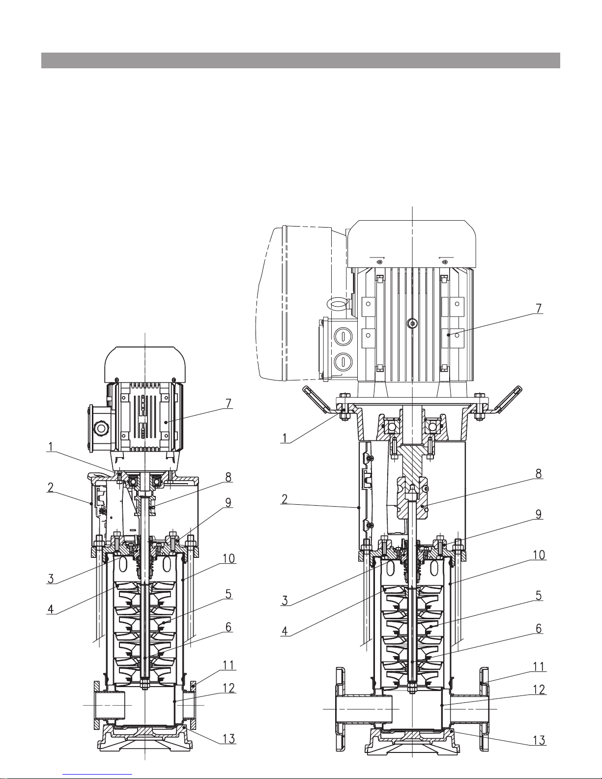
Fig. 1
Page 3
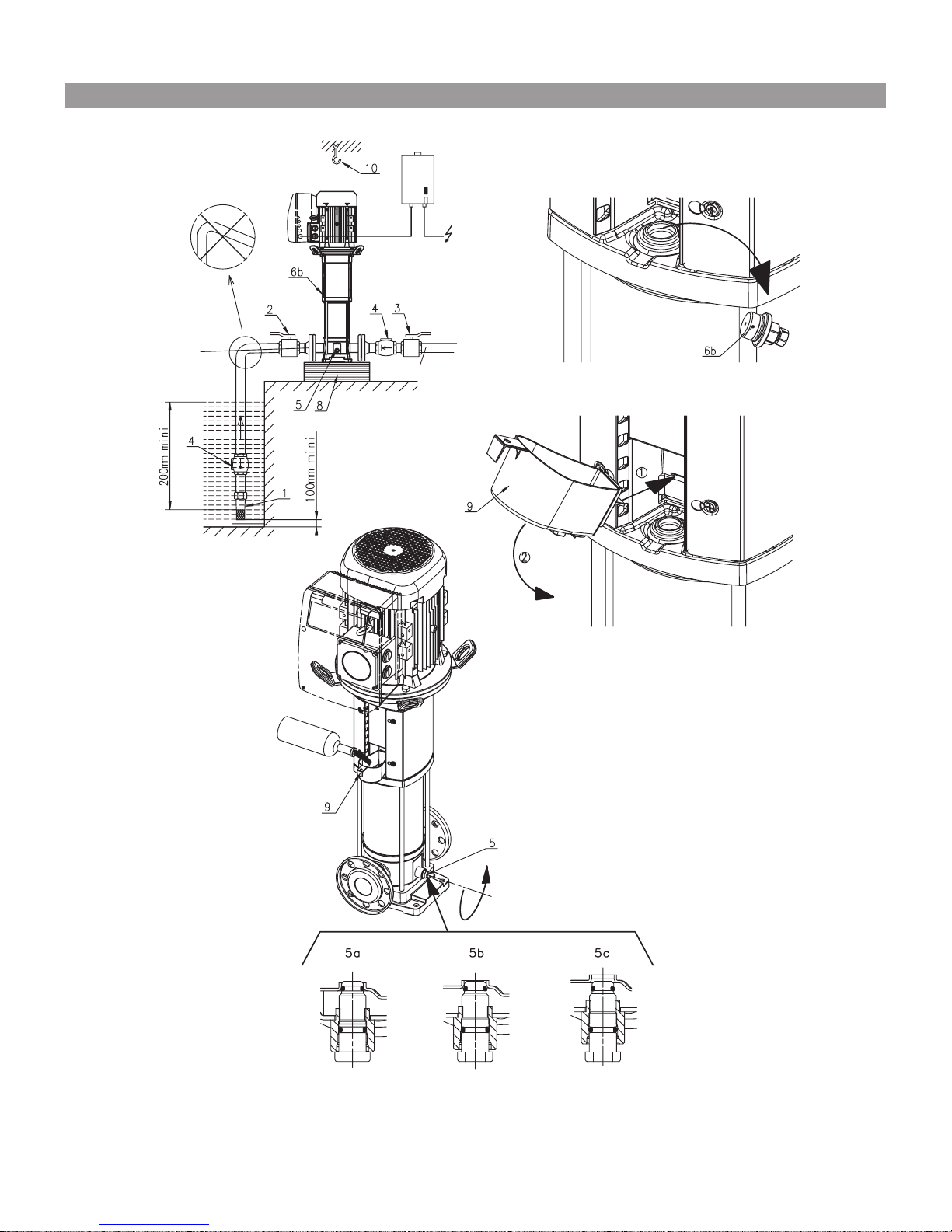
Fig. 2
Page 4
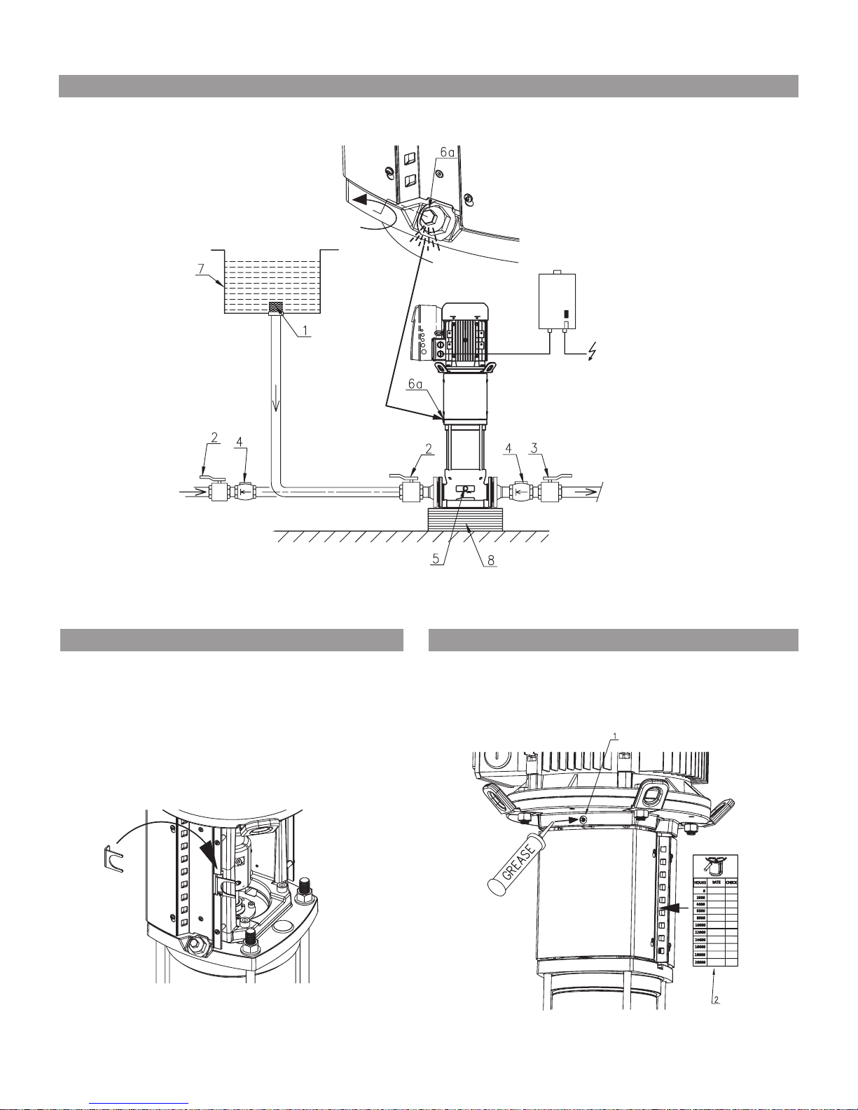
Fig. 3
Fig. 6 Fig. 7
Page 5
D
A
E
FF
DAE
B
C
AK
AJ
AG
AG
AH
AJ
C
B
AK
H
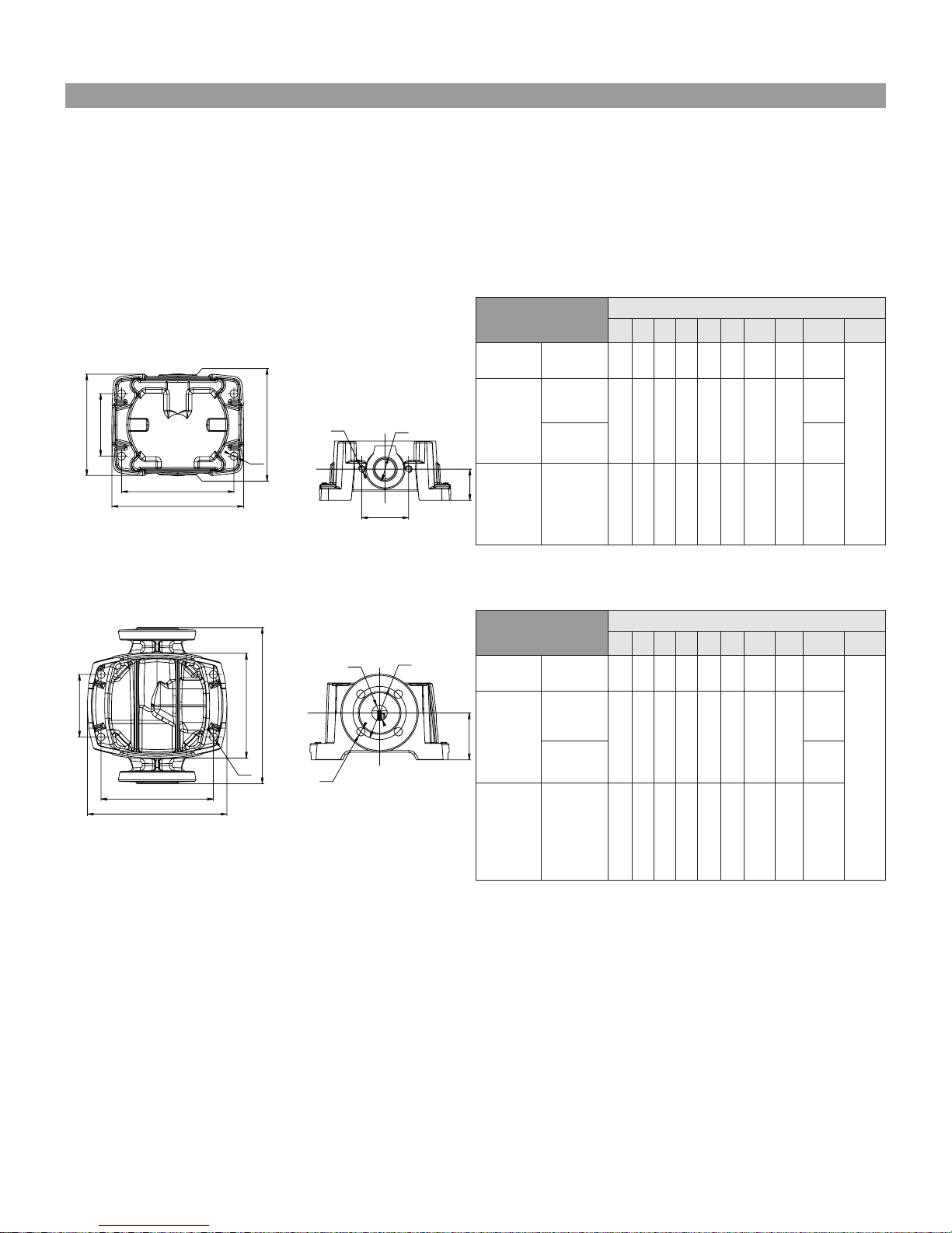
Fig. 4
Type
(mm)
A B C D E F G H J K
Helix VE22
PN16/PN25/
PN30
130 296 215 250 300 90 DN50 125 4 x M16
16 x
Ø14
Helix VE36
PN16
170
or
220
296
240
or
220
250 320 105 DN65 145
4 x M16
PN25/PN30 8 x M16
Helix VE52
PN16/PN25/
PN30
190
or
220
296
266
or
220
250 365 140 DN80 160 8 x M16
Type
(mm)
A B C D E F G H J K
Helix VE22
PN16/PN25 130 255 215 226 300 90 DN50 125 4 x M16
4 x
Ø14
Helix VE36
PN16
170 284 240 230 320 105 DN65 145
4 x M16
PN25 8 x M16
Helix VE52
PN16/PN25
190
or
170
310
266
or
240
234 365 140 DN80 160 8 x M16
-2 -3
-1
Page 6

Fig. 8
;
;
;
Page 7
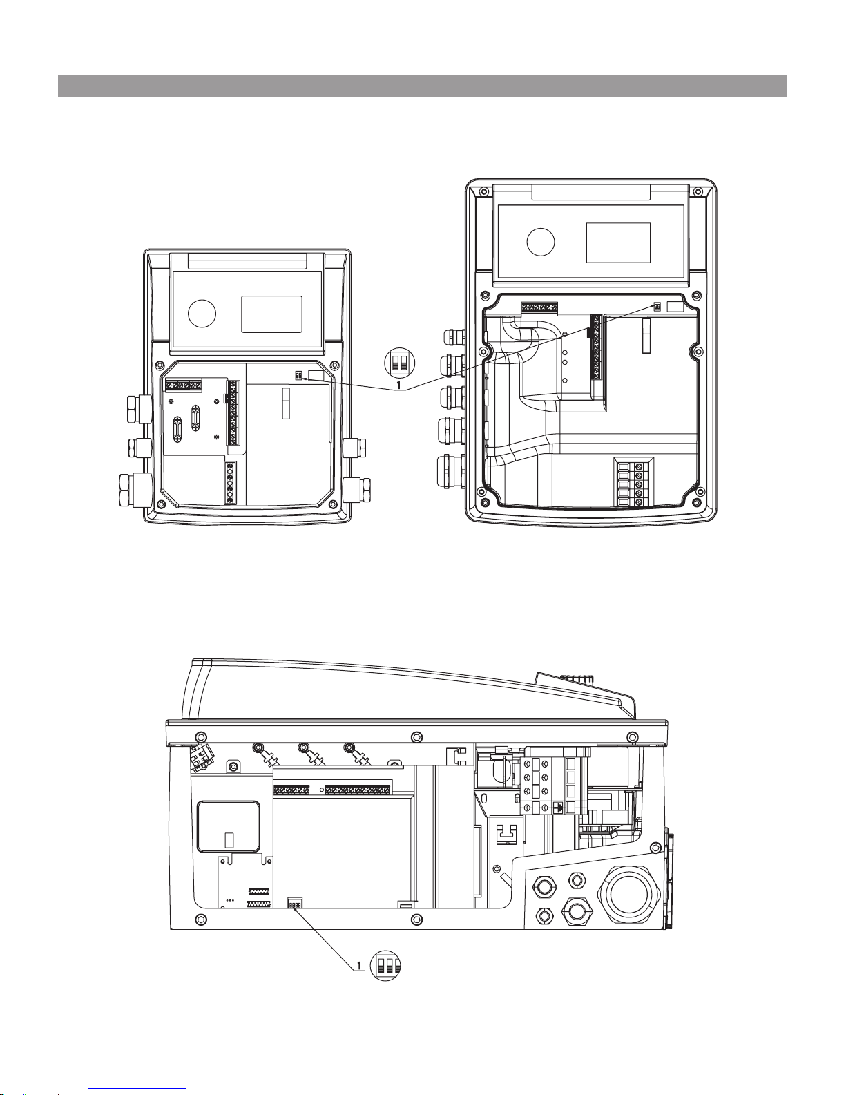
Fig. A1
1
1
Page 8
2
4
3
Fig. A2
Fig. A3
4
3
2
Fig. A4
3
4
2
Page 9

1. General
1.1 About this document
The language of the original operating instructions is English. All other languages of these
instructions are translations of the original operating instructions.
These installation and operating instructions are
an integral part of the product. They must be kept
readily available at the place where the product is
installed. Strict adherence to these instructions
is a precondition for the proper use and correct
operation of the product.
These installation and operating instructions correspond to the relevant version of the product and
the underlying safety standards valid at the time
of going to print.
EC declaration of conformity:
A copy of the EC declaration of conformity is a
component of these operating instructions.
If a technical modification is made on the designs
named there without our agreement, this declaration loses its validity.
2. Safety
These operating instructions contain basic information which must be adhered to during installation,
operation and maintenance. For this reason, these
operating instructions must, without fail, be read by
the service technician and the responsible specialist/operator before installation and commissioning.
It is not only the general safety instructions listed
under the main point “safety” that must be adhered
to but also the special safety instructions with
danger symbols included under the following main
points.
2.1 Indication of instructions in the operating
instructions
Symbols
General danger symbol
Danger due to electrical voltage
Note
Signal words:
DANGER! Acutely dangerous situation. Nonobservance results in death or the most serious
of injuries.
WARNING! The user can suffer (serious) injuries.
‘Warning’ implies that (serious) injury to persons
is probable if this information is disregarded.
CAUTION! There is a risk of damaging the product/
unit. “Caution” implies that damage to the product
is likely if this information is disregarded.
NOTE: Useful information on handling the product. It draws attention to possible problems.
Information that appears directly on the product,
such as
• direction of rotation/flow arrow,
• identifiers for connections,
• name plate,
• warning sticker
must be strictly complied with and kept in legible
condition.
2.2 Personnel qualifications
The installation, operating, and maintenance personnel must have the appropriate qualifications
for this work. Area of responsibility, terms of
reference and monitoring of the personnel are to
be ensured by the operator. If the personnel are
not in possession of the necessary knowledge,
they are to be trained and instructed. This can be
accomplished if necessary by the manufacturer of
the product at the request of the operator.
2.3 Danger in the event of non-observance of the
safety instructions
Non-observance of the safety instructions can
result in risk of injury to persons and damage
to the environment and the product/unit. Non
observance of the safety instructions results in
the loss of any claims to damages.
In detail, non-observance can, for example, result
in the following risks:
• Danger to persons from electrical, mechanical
and bacteriological influences,
• Damage to the environment due to leakage of
hazardous materials.
• Property damage
• Failure of important product/unit functions
• Failure of required maintenance and repair procedures
2.4 Safety consciousness on the job
The safety instructions included in these installation and operating instructions, the existing national regulations for accident prevention together with
any internal working, operating and safety regulations of the operator are to be complied with.
2.5 Safety instructions for the operator
This appliance is not intended for use by persons
(including children) with reduced physical, sensory or mental capabilities, or lack of experience
and knowledge, unless they have been given
supervision or instruction concerning use of the
appliance by a person responsible for their safety.
Children should be supervised to ensure that they
do not play with the appliance.
• If hot or cold components on the product/the
unit lead to hazards, local measures must be
taken to guard them against touching.
• Guards protecting against touching moving
components (such as the coupling) must not be
removed whilst the product is in operation.
• Leakages (e.g. from the shaft seals) of hazardous
fluids (which are explosive, toxic or hot) must be
led away so that no danger to persons or to the
environment arises. National statutory provisions
are to be complied with.
38
English
WILO SE 01/2016
Page 10

• Highly flammable materials are always to be kept
at a safe distance from the product.
• Danger from electrical current must be eliminated. Local directives or general directives [e.g.
IEC, VDE etc.] and local power supply companies
must be adhered to.
2.6 Safety instructions for installation and maintenance work
The operator must ensure that all installation
and maintenance work is carried out by authorised and qualified personnel, who are sufficiently
informed from their own detailed study of the
operating instructions.
Work on the product/unit must only be carried out
when at a standstill. It is mandatory that the procedure described in the installation and operating
instructions for shutting down the product/unit
be complied with.
Immediately on conclusion of the work, all safety
and protective devices must be put back in position and/or recommissioned.
2.7 Unauthorised modification and manufacture of
spare parts
Unauthorised modification and manufacture of
spare parts will impair the safety of the product/
personnel and will make void the manufacturer’s
declarations regarding safety.
Modifications to the product are only permissible
after consultation with the manufacturer. Original
spare parts and accessories authorised by the
manufacturer ensure safety. The use of other
parts will absolve us of liability for consequential
events.
2.8 Improper use
The operating safety of the supplied product is
only guaranteed for conventional use in accordance with Section 4 of the operating instructions.
The limit values must on no account fall under
or exceed those specified in the catalogue/data
sheet.
3. Transport and interim storage
When receiving the material, check that it has not
been damaged during transport. If the material
has been damaged during transport, take all necessary steps with the forwarding agent within the
claim period.
CAUTION! Potential damage due to external
influences.
If the delivered material is to be installed at a later
date, store it in a dry place and protect it from
impacts and any external influences (humidity,
frost etc.).
The product should be cleaned thoroughly before
it is put into temporary storage. The product can
be stored for at least one year.
Handle the pump carefully to avoid any damage prior
to installation.
4. Intended use
This pump has been designed to pump hot or cold
water, water/glycol mixtures or other low-viscosity liquids that are free of mineral oil, solid or
abrasive substances, or materials containing long
fibres. Pumping corrosive chemicals requires the
manufacturer’s approval.
CAUTION! Risk of explosion!
Do not use this pump for any flammable or
explosive liquids.
4.1 Applications areas
- water distribution and pressure boosting,
- industrial circulation systems,
- process fluids,
- cooling-water circuits,
- fire-fighting and washing stations,
- irrigation systems, etc.
39
English
WILO SE 01/2016
Page 11

5. Technical data
5.1 Type key
Exemple: Helix VE2205/2-1/16/E/KS/xxxx
Helix V Vertical high-pressure multistage centrifugal pump in in-line design
E With converter for electronic speed control
22 Nominal ow in m3/h
05 Number of impellers
2 Number of trimmed impellers (if any)
1
Pump material code
1 = Pump housing Stainless steel 1.4308 (AISI 304)
+ Hydraulics 1.4307 (AISI 304)
2 = Modular pump housing Stainless steel 1.4409 (AISI 316L)
+ Hydraulics 1.4404 (AISI 316L)
3 = Modular pump housing Cast Iron EN-GJL-250 (ACS and WRAS approved coating)
+ Hydraulics 1.4307 (AISI 304)
4 = Monobloc Pump housing cast iron EN-GJL-250 (ACS and WRAS approved coating)
+ Hydraulics 1.4307 (AISI 304)
5 = Monobloc Pump housing cast iron EN-GJL-250 (standard coating)
+ Hydraulics 1.4307 (AISI 304)
16
Pipe connection
16 = PN16
25 = PN25
30 = PN40
E
Seal type code
E = EPDM
V = FKM
KS
K = Cartridge seal, versions without “K” are equipped with simple mechanical seal
S = Lantern orientation align with suction pipe
Bare-shaft pump (without motor)
50
60
Motor frequency ( Hz)
-38FF265
Ø motor shaft –
lantern size
xxxx Options code (if any)
40
English
WILO SE 01/2016
Page 12
5.2 Technical data
- Electromagnetic compatibility(*)
• emission in residential areas –
1st environment: PN-EN 61800-3
• electromagnetic immunity in industrial environments –
2nd environment: PN-EN 61800-3
(*) In the frequency range between 600 MHz and 1 GHz,
the display or the pressure indication in the display
might be disturbed in the direct vicinity (< 1 m from the
electronic module) of radio transmission installations,
transmitters or similar devices working in this frequency
range. The function of the pump is not affected at any
time.
Maximum operating pressure
Pump casing 16, 25 or 30 bars depend on the model
Maximum suction pressure
10 bars
Note: real inlet pressure (P Inlet) + pressure at 0 ow delivered by the
pump must be below the maximum operating pressure of the pump. In
case of exceeding maximum operating pressure, the ball bearing and the
mechanical seal could be damaged or lifetime could decrease.
P Inlet + P at 0 ow ≤ Pmax pump
See pump nameplate to know the maximum operating pressure : Pmax
Temperature range
Liquid temperatures
-20°C to +120 °C
-30°C to +120° C (if full stainless steel)
-15°C to + 90°C (Viton version for O’ring and mechanical seal )
Ambient temperature
-15°C to +50 °C
On request for other temperature
Electrical data
Motor efciency Motor according to IEC 60034-30
Motor Protection index IP 55
Insulation class 155 (F)
Frequency See motor plating
Electrical voltage See motor plating
Other data
Humidity < 90% without condensation
Altitude < 1000 m (> 1000m on request)
Maximum suction head according to NPSH of the pump
Sound pressure level dB(A)
0/+3 dB(A)
Power (kW)
0.55 0.75 1.1 1.5 2.2 3 4 5.5 7.5 11 15 18.5 22
61 63 67 71 72 74 78 81
Cross-section of power cable
(cable comprising of 4 wires) mm
2
Power (kW)
0.55 0.75 1.1 1.5 2.2 3 4 5.5 7.5 11 15 18.5 22
1.2 1.5-2.5 2.5 – 4
2.5 – 6
4 – 6
6 – 10
10 – 16
Outline and pipe dimensions (Fig. 4).
5.3 Scope of delivery
• Multistage pump
• Installation and operating instructions
41
English
WILO SE 01/2016
Page 13

5.4 Accessories
The following original accessories are available for
the Helix range:
• IF-module PLR for connecting to PLR/interface
converter.
• IF-module LON for connection to LONWORKS
network. These modules plug directly into the
connection interfaces of the converter
(see fig. below).
• Non-return valves (with tab or spring ring for
operation at constant pressure).
• Protection kit against dry-running.
• Sensor kit for pressure regulation (accuracy:
≤ 1 % ; use between 30 % and 100 % of the
measuring range).
Use only accessories that are new.
6. Description and function
6.1 Description of the product
FIG. 1
1 – Motor connection bolt
2 – Coupling guard
3 – Cartridge seal
4 – Hydraulic stage housing
5 – Impeller
6 – Pump shaft
7 – Motor
8 – Coupling
9 – Lantern
10 – Tube liner
11 – Flange
12 – Pump casing
13 – Base plate
Designation
Article no.
2
Round counterflanges, stainless steel,
1.4404 (PN16 – DN50) 4038587
2
Round counterflanges, stainless steel,
1.4404 (PN25 – DN50) 4038589
2 Round counterflanges, steel,
(PN16 – DN50) 4038585
2 Round counterflanges, steel,
(PN25 – DN50) 4038588
2
Round counterflanges, stainless steel,
1.4404 (PN16 – DN65) 4038592
2
Round counterflanges, stainless steel,
1.4404 (PN25 – DN65) 4038594
2 Round counterflanges, steel,
(PN16 – DN65) 4038591
2 Round counterflanges, steel,
(PN25 – DN65) 4038593
2
Round counterflanges, stainless steel,
1.4404 (PN16 – DN80) 4073797
2
Round counterflanges, stainless steel,
1.4404 (PN25 – DN80) 4073799
2 Round counterflanges, steel,
(PN16 – DN80) 4072534
2 Round counterflanges, steel,
(PN25 – DN80) 4072536
Bypass kit 25 bar
4124994
Bypass kit (with pressure gauge 25 bar)
4124995
Baseplate with dampers for pumps up to 5.5kW
4157154
Power (kW)
0.55 0.75 1.1 1.5 2.2 3 4
Power (kW)
5.5 7.5
5,
57
,5
Power (kW)
11 15 18.5 22
42
English
WILO SE 01/2016
Page 14

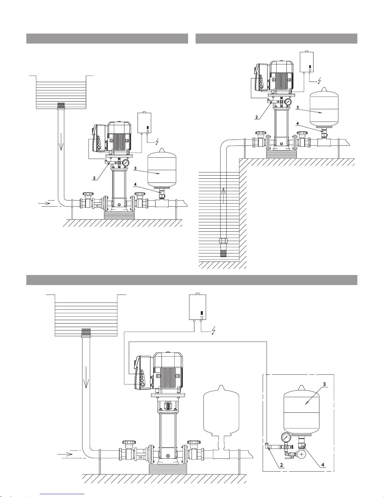
FIG. 2, 3
1 – Strainer
2 – Pump suction valve
3 – Pump discharge valve
4 – Check valve
5 – Drain + priming plug
6 – Venting plug and filling plug
7 – Tank
8 – Foundation block
9 – Option: pressure plugs (a – suction,
b – discharge)
10 – Lifting hook
FIG. A1, A2, A3, A4
1 – Switch block
2 – Pressure sensor
3 – Tank
4 – Insulation valve of the tank
6.2 Function of the product
•
Helix pumps are vertical multistage high-pressure
non-self-priming pumps for in-line connection.
• Helix pumps combine highly efficient hydraulic
systems and motors (if present).
• All metal components in contact with the fluid
are made of stainless steel or grey cast iron.
• Special versions for aggressive liquids exist with
all components in contact with the liquid being
made of stainless steel.
• A cartridge seal is used as standard for all products
of the Helix range to facilitate maintenance.
• For models equipped with the heaviest motor
(>40 kg), a specific coupling allows the seal to
be replaced without removing the motor.
• The Helix lantern design includes an additional
ball bearing that takes up hydraulic axial forces:
this allows the pump to be fitted with an entirely
standard motor.
• Special handling devices are integrated to facilitate pump installation (Fig. 8).
7. Installation and electrical connection
All installation and electrical work may only be
carried out by qualified personnel and in compliance with local codes and regulations!
WARNING! Risk of severe injury!
Ensure that all existing regulations concerning the
prevention of accidents are observed.
WARNING! Risk of electrical shock!
Ensure that any electrical hazard is avoided.
7.1 Commissioning
Unpack the pump and dispose of the packaging
in accordance with all regulations concerning the
protection of the environment.
7.2 Installation
The pump must only be installed in a dry,
well-ventilated and frost-free location.
CAUTION! Risk of damage to the pump!
Contamination and solder residue in to the pump
body may affect pump operation.
• It is recommended to perform any welding and
soldering work before installing the pump.
• Flush the system thoroughly before
installing the pump.
- Install the pump in an easily accessible position to
facilitate inspection or replacement.
-
For heavy pumps, install a lifting hook (Fig.2, Pos.
12) above the pump to facilitate its disassembly.
WARNING! Hot surface! Risk of burns!
Position the pump in such a way that any contact with hot pump surfaces is prevented during
operation.
- Install the pump in a dry and frost-free place on
a flat concrete block using appropriate accessories. If possible, use an insulating material under
the concrete block (cork or reinforced rubber) to
avoid any noise and vibration transmission into
the installation.
WARNING! Risk of tipping!
Ensure that the pump is correctly secured to the
ground.
- The pump must be installed in an easily accessible
location to facilitate inspection and removal work.
The pump must always be installed perfectly
upright on a sufficiently heavy concrete base.
CAUTION! Hazard caused by foreign parts
inside the pump!
Ensure that all blanking plugs are removed from
the pump housing before installation.
NOTE: All pumps are factory-tested for their
hydraulic properties and may therefore contain
small amount of residual water. For hygienic purposes, it is recommended to rinse the pump before
any installing it in any potable water supply.
- For installation and connection dimensions see
section 5.2.
- Lift the pump only with appropriate lifting devices and suitable slings in compliance with lifting
regulations. The integrated lifting hooks must be
used for lifting and the fixation of the pump.
WARNING! Risk of tipping!
There is a high risk of falling due to the high position of the centre of gravity especially for larger
pumps. Take special care to the safe fixation of the
pump during handling.
WARNING! Risk of tipping!
Use integrated lifting hooks only if they are not
damaged (e.g. by corrosion). Replace them, if
required.
WARNING! Risk of tipping!
Never lift the complete pump using the motor
hooks as these are designed to lift the motor only.
- Motors are equipped with drain holes for condensed water that are sealed at the factory by
plastic plugs to ensure IP55 protection. If used in
air-conditioning or cooling systems, remove these
plugs to allow draining.
43
English
WILO SE 01/2016
Page 15

7.3 Pipe connection
- Connect the pump to the pipes by using appropriate counterflanges, bolts, nuts and gaskets.
CAUTION!
Tightening of screws or bolts must not exceed:
The use of an impact wrench is prohibited.
- The flow direction of the pump is indicated on
the rating plate of the pump.
- The pump must be installed so that it does
induce any stress into the pipework. The pipes
must be attached so that the pump does not
bear their weight.
- The installation of insulation valves on the suction and discharge side of the pump is recommended.
- Use expansion joints to mitigate noise and vibration, if required.
- The nominal cross-section of the suction pipe
should be at least as large as that of the pump
connection.
- The installation of a check valve in the discharge
pipe is recommended to protect the pump
against pressure impulses.
- When directly connected to a public drinking
water system, the suction pipe must be fitted
with a check valve and a guard valve.
- When indirectly connected via a tank, the suction pipe must be equipped with a strainer to
protect pump and check valve against impurities.
- In case of half flanges pump design, it is recommended to connect the hydraulic network and
then keep out the plastic fixation links to prevent any leakage risk.
7.4 Motor connection for bare-shaft pump
(without motor)
- Remove the coupling guards.
NOTE: Coupling guards can be removed without
removing the screws completely.
- Attach the motor to the pump using screws (for
FT lantern size – see product designation) or
screws, nuts and handling devices (for FF lantern
size – see product designation) provided with
the pump. Verify motor power and dimensions in
Wilo catalogue.
NOTE: Motor ower can be adjusted in accordance
with the fluid’s characteristics. Contact the Wilo
customer service, if required.
- Close the coupling guards by tightening all
screws provided with the pump.
7.5 Electrical connections
WARNING! Risk of electrical shock!!!
Ensure that any electrical hazard is avoided.
• Electrical work must only be carried out by
qualified electricians!
• Ensure that the power supply is switched off
and secured against unauthorised switching
before making any electrical connections.
• Safe installation and operation requires the
pump to be properly earthed at the power supply’s grounding terminals.
- Check that operating current, voltage and frequency comply with the specifications on the
motor rating plate.
- The pump must be connected to the power
supply by a solid cable equipped with an earthed
plug-connection or a main power switch.
- Three-phase motors must be connected to an
approved motor starter. The set nominal current
must correspond to the electrical data specified
on the pump motor rating plate.
- The supply cable must be routed in such a way
that it does not contact the pipework and/or
pump and motor casing.
- Pump and/or installation must be earthed in
compliance with local regulations. A residual
current device (RCD) may be used for extra protection.
- The power cable (3 phases + earth) must be fed
through the threaded cable connection shown in
black below.
Non-assigned threaded cable connections must
remain sealed with the plugs provided by the
manufacturer.
Power (kW)
0.55 0.75 1.1 1.5 2.2 3 4 5.5 7.5 11 15 18.5 22
M25
M25
M32/M40
Configuration PN16 / PN25
M10 – 20 N.m M12 – 30 N.m
Configuration PN40
M12 – 50 N.m M16 – 80 N.m
44
English
WILO SE 01/2016
Page 16

• The input cables for sensor, external setpoint,
[Ext.off] and [Aux] must be shielded.
Power (kW)
5.5 7.5
1
2
3
4
The metal threaded cable connections of the converter are
prepared for the connection of braided shielding.
Power (kW)
11 15 18.5 22
Cable, shielded
1xM32/40
1xM20
1xM16
2xM12
M12
M16
M16
M20
M25
Power (kW)
0.55 0.75 1.1 1.5 2.2 3 4
Cable, shielded
M20
M12
M25
M12
M16
45
English
WILO SE 01/2016
Page 17

NOTE: Requirements and limits for harmonic currents.
Pumps with the engine-power classes of 11 kW,
15 kW, 18.5 kW and 22 kW are equipment for
professional usage. These pumps are subject to
special connectivity conditions since a short-circuit ratio Rsce of 33 at the connecting point is not
sufficient. The connection to the public low-voltage systems is regulated by the standard IEC
61000-3-12 – the basis for these pumps’ rating
is table 4 for (balanced) three-phase pumps under
specified conditions. For all public connection
points, the short-circuit power Ssc at the interface between the user’s electrical installation and
the public power system must be greater than or
equal to the values in the table below. It is the
responsibility of the installer or of the user of
the pumps to ensure that the pump is operated
properly, consultation the distribution network
operator if necessary. If the pump is used within
an industrial middle-voltage system, the connectivity conditions are the sole responsibility of the
operator.
By installing an appropriate harmonic filter between the pump and the power supply, the harmonic current content will be reduced, if needed.
- The electric characteristics (frequency, voltage,
nominal current) of the frequency converter
are specified on the pump identification label.
Ensure that the frequency converter complies
with the mains supply.
- The electric protection of the motor is integrated
into the converter. The parameters must comply
with the pump characteristics and must ensure
the protection of pump and motor.
- In case of impedance between earth and neutral
point, install a protection device upstream of the
frequency converter.
- Provide a fused isolation switch (type gF) to protect the mains installation.
NOTE: If a residual current device (RCD) is installed
for user protection, it must have a delay effect.
Adjust it according to the current mentioned on
the pump identification label.
NOTE: This pump is equipped with a frequency
converter and may not be protected by a residual
current device. Frequency converters can impair
the function of residual current circuits.
Exception: Residual current devices (RCDs) with
selective and universal-current sensitivity may
be used.
• Labelling: RCD
• Trigger current: > 30 mA.
- Use only power cables complying with applicable
regulations.
- Max. permissible mains side fuse protection:
25 A.
Trigger characteristic of the fuses: B.
As soon as the power supply to the electronic module is established, a 2-second display test is carried
out during which all characters on the display are
shown.
46
English
Motor power [kW] Short circuit power SSC [kVA]
11 1800
15 2400
18,5 3000
22 3500
WILO SE 01/2016
Page 18

Connection terminal assignment.
- Remove the screws and take off the converter
cover.
NOTE: Terminals IN1,IN2, GND and Ext. Off meet the requirements for „safe isolation“ (in acc. with EN61800-5-1) at
the mains terminals as well as at SBM and SSM terminals (and
vice versa).
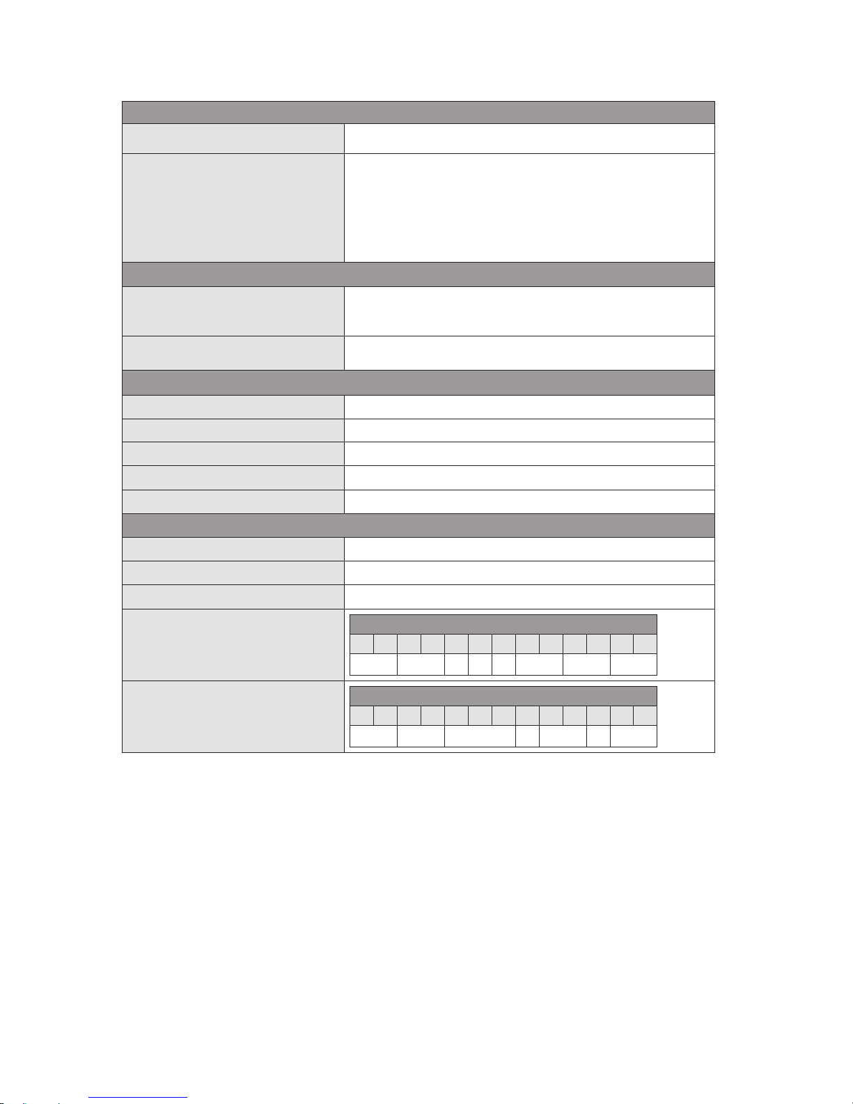
Designation Allocation Notes
L1, L2, L3 Mains connection voltage Three-phase current 3 ~ IEC38
PE Earth connections
IN1 Input sensor
Type of signal: Voltage (0 – 10 V, 2 – 10 V)
Input resistance: Ri ≥ 10 kΩ
Signal type: current (0 – 20 mA, 4 – 20 mA)
Input resistance: Rb = 500 Ω
Can be configured in the „Service“ menu <5.3.0.0>
IN2 External input setpoint Type of signal: Voltage (0 – 10 V, 2 – 10 V)
Input resistance: Ri ≥ 10 kΩ
Signal type: current (0 – 20 mA, 4 – 20 mA)
Input resistance: Rb = 500 Ω
Can be configured in the „Service“ menu <5.4.0.0>
GND (x2) Earth connections For both input IN1 and IN2
+ 24 V DC voltage for sensor Max. load: 60 mA
The terminal is short-circuit-proof.
Aux Control input (Auxiliary)
„Overriding Off“
for external potential-free switch
The pump can be switched on/off using the external
potential-free contact.
This input is provided for auxiliary functions,
e.g. dry-running sensor, etc.
Ext. off
Control input (ON/OFF)
„Overriding Off“
for external potential-free switch
The pump can be switched on/off using the external
potential-free contact.
In systems with a high cycling frequency
(> 20 on/off cycles per day), on/off-cycling must be
performed via „Ext. off“.
SBM „Available transfer“ relay In normal operation, the relay is activated when the
pump is running or in standby.
The relay is deactivated if an initial defect occurs or if the
main power supply is disconnected (pump stops).
Pump availability is signalled to the control box.
Can be configured in the „Service“ menu <5.7.6.0>
Contact load:
Minimum 12 V DC, 10 mA
Maximum: 250 V AC, 1 A
SSM „Failures transfer“ relay If consecutive defects of the same type are detected
(from 1 to 6 according to significance), the pump stops
and this relay is activated (until manual intervention).
Contact load:
Minimum 12 V DC, 10 mA
Maximum: 250 V AC, 1 A
PLR Connection terminals at
PLR
The optional IF-module PLR must be pushed into the
multiplug in the connection area of the converter.
The connection is protected against reversed polarity.
LON Connection terminals at
LON
The optional IF-module LON must be pushed into the
multiplug in the connection area of the converter.
The connection is twist-proof.
0.55 0.75 1.1 1.5 2.2 3 4 5.5 7.5 11 15 18.5 22
x1 x2
47
English
WILO SE 01/2016
Page 19

Connection to mains supply
Power terminals
Connect the 4-wire cable to the power terminals
(phases + earth).
Connection of inputs / outputs Input/output terminals
• The input cables for sensor, external setpoint, [Ext.off]
and [Aux] must be shielded.
• The remote control allows the pump to be switched On
and Off (free contact), this function has priority over other
functions.
• The remote control can be removed by bridging the terminals (3 and 4).
Example: Float switch, pressure gauge for dry-running,
etc.
L1 L2 L3
GND...
In2...
In1...
Remote
control
ON/OFF
External set value
Sensor 20 mA/10 V
Remote
control
AUXILIARY
not used
GND...
+24 V...
1 2 3 4 5 6 7 8 9 10
11
aux:
ext.off
MP
20mA/10
DDS
48
English
WILO SE 01/2016
Page 20

„Speed control“ connection
Setting the frequency manually:
Setting the frequency via external control:
„Constant pressure“ or „Variable pressure“ connection
Control by pressure sensor:
• 2 wires ([20 mA/10 V]/+24 V)
• 3 wires ([20 mA/10 V] / 0 V/+24 V)
and setpoint turning the rotary knob
Control by pressure sensor:
• 2 wires ([20 mA/10 V]/+24 V)
• 3 wires ([20 mA/10 V] / 0 V/+24 V)
and setpoint setting by external set value
„P.I.D. control“ connection
Control by sensor (temperature, flow rate, etc.):
• 2 wires ([20 mA/10 V]/+24 V)
• 3 wires ([20 mA/10 V] / 0 V/+24 V)
and setpoint turning the rotary knob
Control by sensor (temperature, flow rate, etc.):
• 2 wires ([20 mA/10 V]/+24 V)
• 3 wires ([20 mA/10 V] / 0 V/+24 V)
and setpoint setting by external set value
IN
Remote
control
External
set value
IN
External
set value
Remote
control
Auxiliary control
Auxiliary control
Auxiliary control
Auxiliary control
Auxiliary control
IN
pressure
sensor
Remote
control
IN
pressure
sensor
Remote
control
IN
External
set value
IN
pressure
sensor
Remote
control
IN
pressure
sensor
Remote
control
1 2 3 4 5 6 7 8 9 10
11
aux:
ext.off
MP
20mA/10 DDS
1 2 3 4 5 6 7 8 9 10
11
aux:
ext.off
MP
20mA/10 DDS
1 2 3 4 5 6 7 8 9 10
11
aux:
ext.off
MP
20mA/10 DDS
1 2 3 4 5 6 7 8 9 10
11
aux:
ext.off
MP
20mA/10 DDS
1 2 3 4 5 6 7 8 9 10
11
aux:
ext.off
MP
20mA/10 DDS
1 2 3 4 5 6 7 8 9 10
11
aux:
ext.off
MP
20mA/10 DDS
Auxiliary control
49
English
WILO SE 01/2016
Page 21

DANGER! Danger to life!
Hazardous contact voltage due to discharging converter
capacitors.
- Before any intervention on the converter, wait for
5 minutes after disconnecting from the supply voltage.
- Ensure that all electrical connections and contacts are
voltage-free.
- Verify the correct assignment of the connection terminals.
- Verify that pump and installation are properly earthed.
Control curves
IN1: Input signal in modes „Constant pressure“, „Variable pressure“ and „P.I.D. control“
100%
Sensor signal 4 – 20 mA
0 2 4
20
Input current (mA)
Value
in % of the sensor
measurement range
In case of values between 0 and
2 mA, a cable is considered
as broken.
Safety
range
100%
Sensor signal 0 – 10 V
0
10
Input voltage (V)
Value
in % of the sensor
measurement range
100%
Sensor signal 0 – 20 mA
0 2
20
Input current (mA)
Value
in % of the sensor
measurement range
100%
Sensor signal 2 – 10 V
0
10
Input voltage (V)
Value
in % of the sensor
measurement range
50
English
WILO SE 01/2016
Page 22

100%
Set value 4 – 20 mA
0 2 4
20
Input current (mA)
Set value
in % of the sensor
measurement
range
Converter stopping range
Safety
range
100%
Set value 0 – 10 V
0 1 2
10
Input voltage (V)
Set value
in % of the sensor
measurement
range
Converter stopping range
Safety
range
IN2: Input of external set value control in mode „Constant pressure“, „Variable pressure“ and „P.I.D. control“
IN2: Input of external frequency control in mode „Speed control“
100%
~30%
~30%
External signal 0 – 20 mA
0 2 4
6 10
20
Input current (mA)
Frequency
of converter
Converter stopping range
Safety
range
100%
External signal 4 – 20 mA
0
20
Input current (mA)
Frequency
of converter
Converter stopping range
Safety
range
~30%
3 5
100%
External signal 2 – 10 V
0
10
Input voltage (V)
Frequency
of converter
Converter stopping range
Safety
range
100%
~30%
External signal 0 – 10 V
0 1 2
10
Input voltage (V)
Frequency
of converter
Converter stopping range
Safety
range
51
English
WILO SE 01/2016
Page 23

8.2 Starting the pump
CAUTION! Risk of damage to the pump!
Never operate the pump at zero flow (closed discharge valve).
WARNING! Risk of injury!
Coupling guards must be in place and secured by all
relevant fasteners when the pump is running.
WARNING! Harmful noise!
High-power pumps may emit a high noise level.
Use appropriate protection when staying close to
the pump for any extended period.
WARNING!
The installation must be laid out in such a way that
there is no risk of injury in case of liquid leakage
(e.g. caused by mechanical seal failure).
8. Commissioning
8.1 System priming and venting
CAUTION! Risk of damage to the pump!
Never operate the pump in a dry state.
Ensure that the system primed before starting
the pump.
8.1.1 Venting process – Operation with sufficient
supply pressure (Fig. 3)
- Close the two guard valves (2, 3).
- Unscrew the venting plug (6a).
- Slowly open the guard valve on the suction side (2)
and completely fill the pump.
- Tighten the venting plug after the air has
escaped and pumped liquid begins to flow (6a).
WARNING!
If the pumped fluid is hot and under high pressure,
the fluid escaping at the venting plug may cause
burns or other injuries.
- Open the guard valve on the suction side completely (2).
- Start the pump and verify that the flow direction
complies with the specification on the pump rating plate. If this is not the case, interchange two
phases in the terminal box.
CAUTION! An incorrect flow direction will cause
a poor pump performance and may damage the
coupling.
- Open the guard valve on the discharge side (3).
8.1.2 Venting process – Pump in suction mode
(Fig.2)
- Close the guard valve on the discharge side (3).
Open the guard valve on the suction side (2).
- Remove the filling plug (6b).
- Partially open the venting plug (5b).
- Fill pump and suction pipe with water.
- Ensure that there is no air trapped in the pump
and suction pipe. Fill the system until all air is
removed.
- Close the filling plug with the venting plug (6b).
- Start the pump and verify that the flow direction
complies with the specification on the pump rating plate. If this is not the case, interchange two
phases in the terminal box.
CAUTION! An incorrect flow direction will cause
a poor pump performance and may damage the
coupling.
- Slightly open the guard valve on the discharge
side (3).
- Unscrew the venting plug from the filling plug to
remove the air (6a).
- Tighten the venting plug when the air has
escaped and pumped liquid begins to flow.
WARNING!
If the pumped fluid is hot and under high pressure,
the liquid escaping at the venting plug may cause
burns or other injuries.
- Fully open the guard valve on the discharge side(3).
- Close the drain plug (5a).
52
English
WILO SE 01/2016
Page 24

8.3.4 Display
Display status page
• The status page appears as the default page of
the display.
The currently set setpoint is displayed.
Basic settings are displayed by symbols.
Example of display status page
NOTE: If the rotary knob is not activated within
30 seconds in any of the menus, the display
returns to the status page without saving the
change.
Navigation element
• The menu structure allows to call the functions
of the converter. A number is attributed to every
menu and submenu.
• Turn the rotary knob to scroll through any menu
level (e.g. 4000 -> 5000).
• Blinking elements (value, menu number, symbol
or icon) allow the selection of a new value, a new
menu number or a new function.
8.3 Operation with frequency converter
8.3.1 Control elements
The converter is controlled using the following
control elements:
Rotary knob
• Selecting a new parameter only requires
rotating the knob in
direction „+“ to the
right or „-“ to the left.
• A short impulse on the rotary knob confirms this
new setting.
Switches
• This converter has a block with two switches
with two positions (Fig. A1, Pos. 1):
• Switch 1 switches between „OPERATION“ mode
[switch 1->OFF] and „SERVICE“ mode [switch
1->ON]. Position „OPERATION“ enables the
selected mode and prevents access to parameter
input (normal operation). Position „SERVICE“ is
used to enter the parameters for different operations.
• Switch 2 activates or deactivates the
„Accesslock“ (see section 8.5.3).
8.3.2 Display structure
8.3.3
Description of standard symbols
Pos. Description
1 Menu number
2 Value display
3 Units display
4 Standard symbols
5 Icon display
Symbol Description
Operation in „Speed control“ mode.
Operation in „Constant pressure“ or
„P.I.D. control“ mode.
Operation in „Variable pressure“
or „P.I.D. control“ mode.
Access locked.
When this symbol appears, current
settings or measurements cannot be
changed. The information displayed
is for reading purposes only.
BMS (Building Management System)
PLR or LON is active.
Pump is running.
Pump has stopped.
1 2
ON
53
English
WILO SE 01/2016
Page 25

8.3.5 Menu description
List (Fig. A5)
<1.0.0.0>
• Turn the rotary knob to adjust the setpoint.
The display changes to menu <1.0.0.0> and the
setpoint starts flashing. Rotate the rotary knob
further (or use the arrows) to increase or decrease the value.
• Press the rotary knob to confirm the change, the
display returns to the status page.
<2.0.0.0>
• The available operating modes are „Speed cont-
rol“, „Constant pressure“, „Variable pressure“ and
P.I.D control.
<3.0.0.0>
<4.0.0.0>
• Menu „Information“ displays measuring, device
and operating data (Fig. A6).
<5.0.0.0>
• Menu „Service“ provides access to the converter
parameter setting.
<6.0.0.0>
• If one or several defects occur, the defects page
appears.
The letter „E“ followed by a three digit code
appears (see section 11).
<7.0.0.0>
• The „Access lock“ is available when switch 2 is in
the ON position.
CAUTION! Risk of material damage!
Inadequate setting changes may cause pump
operation faults which may lead to material
damage of the pump or installation.
• Settings in „SERVICE“ mode should only be made
during commissioning and by qualified personnel
only.
Symbol Description
When the arrow appears:
• Press the rotary knob to access the
submenu (e.g. 4000 -> 4100).
When the arrow „return“ appears:
• Press the rotary knob to access
the next higher menu (e.g. 4150 ->
4100).
Position Switch 1 Description
OPERATION OFF
Adjustment of the setpoint, possible for both
cases.
SERVICE ON
Position Switch 1 Description
OPERATION OFF
Setting the pump ON/
OFF.
SERVICE ON
Position Switch 1 Description
OPERATION OFF
Reading of operating
modes only.
SERVICE ON
Setting of operating
modes.
Position Switch 1 Description
OPERATION OFF
Read-only display of the
„Information“ menu.
SERVICE ON
Position Switch 1 Description
OPERATION OFF
Read-only display of the
„Service“ menu.
SERVICE ON
Setting for „Service“
menu.
Position Switch 1 Description
OPERATION OFF
Display of the fault page.
SERVICE ON
Position Switch 1 Description
OPERATION OFF
Display of „Access lock“
symbol.
SERVICE ON
54
English
WILO SE 01/2016
Page 26

Fig. A5
55
English
WILO SE 01/2016
Navigation in basic menus in normal operation
(Switch 1 = OFF in „OPERATION“ position)
Setpoint
Control type
Information
Service
Fault
acknowledgement
Pump
Appears when a fault is
triggered
Page 27

Fig. A6
Navigation in menu <4.0.0.0> „Information“
56
English
WILO SE 01/2016
Information
Power
Operating data
Actual conditions
Device data
Operating hours
Consumption
Power-on
counter
SSM relay
Pump name
User controller
software version
Motor controller
software version
SBM relay
Ext. off
Actual values
Pressure
or %
Not displayed if
speed control is active
See section 10 – Menu <5.6.7.0>
Default “Available transfer”
Page 28

Parameterisation of menu <2.0.0.0> and <5.0.0.0>
In „SERVICE“ mode, menu parameters <2.0.0.0> and <5.0.0.0> can be adjusted.
The following two setting modes exist:
• „Easy Mode“: provides quick access to the 3 operating modes.
• „Expert Mode“: provides access to all existing parameters.
• Set switch 1 to the ON position (Fig. A1, Pos. 1).
• „SERVICE“ mode is activated.
This symbol flashes on the status page of the display (Fig. A7).
ON
1
S
Easy Mode
• Press the rotary knob within 2 seconds. The symbol „Easy Mode“ appears (Fig. A7).
• Press the rotary knob to confirm the selection. The display changes to menu <2.0.0.0>.
„Easy Mode“ facilitates the quick setting of the 3 operating modes (Fig. A8)
• Speed control“
• „Constant pressure“/“Variable pressure“
• „P.I.D. control“
• After setting, set switch 1 to the OFF position (Fig. A1, Pos. 1).
Expert Mode
• Press the rotary knob within 2 seconds. Go to Expert Mode, the symbol „Expert Mode“ appears (Fig.A7).
• Press the rotary knob to confirm the selection. The display changes to menu <2.0.0.0>.
First, select the operating mode in menu <2.0.0.0>.
• „Speed control“
• „Constant pressure“/“Variable pressure“
• „P.I.D. control“
Then, in menu <5.0.0.0>, the Expert Mode provides access to all converter parameters (Fig. A9).
• After setting, set switch 1 to the OFF position (Fig. A1, Pos. 1).
Fig. A7
Easy Mode
Expert Mode
Control type
Easy Mode
Control type
Expert Mode
Pump
Information
Service
Setpoint
SERVICE
OPERATION
1 2
ON
1 2
ON
57
English
WILO SE 01/2016
Page 29

Fig. A8
EASY
MENU
External setpoint input – IN2
Selection of signal type
External setpoint input – IN2
Selection of signal type
Variable pressure
58
English
WILO SE 01/2016
Speed control
With internal setpoint
External setpoint input – IN2
disabled – Selection OFF
External setpoint input – IN2
enabled – Selection ON
With external setpoint
With internal setpoint
With external setpoint
With internal setpoint
With external setpoint
Constant pressure
P.I.D. control
Sensor input – IN1
Selection of pressure sensor
Sensor input – IN1
Selection of signal type
Sensor input – IN1
Selection of signal type
External setpoint input – IN2
disabled – Selection OFF
External setpoint input – IN2
disabled – Selection OFF
External setpoint input – IN2
enabled – Selection ON
External setpoint input – IN2
Selection of signal type
Parameterisation P.I.D.
Selection value „P“ (0.0-300.0)
Parameterisation P.I.D.
Selection value „I“ (10 ms – 300 s)
Parameterisation P.I.D.
Selection value „D“ (0 ms – 300 s)
Parameterisation P.I.D.
Selection value „P“ (0.0-300.0)
Parameterisation P.I.D.
Selection value „I“ (10 ms – 300 s)
Parameterisation P.I.D.
Selection value „D“ (0 ms – 300 s)
External setpoint input – IN2
enabled – Selection ON
Page 30

Fig. A9
EXPERT
MENU
59
English
WILO SE 01/2016
Service
BMS – Building Management System
IN1 – „Sensor input“
IN2 – External setpoint input
PID – parameters
Other settings
Only displayed when BMS is active.
See instructions for this product
Not shown when „Speed control“
is enabled
Not shown when „IN2“ is disabled
Not shown when „PID Control“ is
enabled
Only displayed when „PID Control“
is enabled
Only displayed when
„Constant Pressure“ or „Variable
Pressure“ is enabled
Sensor range
Selection of signal type
Selection
Selection
parameters „P“
Selection
parameters „I“
Selection
parameters „D“
Zero flow delay
period
Selection of
reduced frequency
Selection of
SBM relay
Factory settings
Selection of signal type
Page 31

Access lock
Function „Access lock“ can be used to lock the
pump settings.
To activate or deactivate this function, proceed
as follows:
• Set switch 2 to the ON position (Fig. A1, Pos. 1).
Menu <7.0.0.0> is called up.
• Turn the rotary knob to enable or disable the
locking function. The current state of the locking
function is indicated by the following symbols:
Lock enabled: Parameters are locked,
menus are accessible in read-only
mode only.
Lock disabled: Parameters can be
changed, access to menus is allowed
to make setting.
• Return switch 2 to the OFF position (Fig. A1,
Pos.1). The display returns to the status page.
8.3.6 Configurations
NOTE: If the pump is supplied as separate part
and as an integral part of a system assembled by
us, the standard configuration mode is „Speed
control“.
„Speed control“ mode (Fig. 2, 3)
Setting the frequency manually or by external
control:
• For starting up, we recommend to set the motor
speed to 2400 RPM.
„Constant pressure“ and
„Variable pressure“ mode (Fig. A2, A3, A7)
Regulation by pressure sensor and setpoint (internal or external).
In case of variable pressure mode put off the zero
flow delay time in menu 5.7.3.0.
• The addition of a pressure sensor (with tank;
sensor kit supplied as accessory) allows the
pump to be pressure-controlled (with no water
in the tank, pressurise the tank to a pressure of
0.3 bar below the pressure control value of the
pump).
• The accuracy of the sensor shall be ≤ 1 %, and it
should be used between 30 % and 100 % of the
measuring range. The tank must have a usable
volume of at least 8 litres.
• For starting up, we recommend a pressure set
value of 60 % of the maximum pressure.
„P.I.D. control“ mode
Control by a sensor (temperature, flow rate, etc.)
by P.I.D. control and setpoint (internal or external).
9. Maintenance
All servicing must be performed by an authorized service representative only!
WARNING! Risk of electrical shock!
Ensure that any electrical hazard is avoided.
Ensure that the power supply is switched off and
secured against unauthorised switching before
performing any work on the electric system.
WARNING! Risk of scalding!
In case of high water temperatures and high system pressures, close the insulating valves upstream
and downstream of the pump.
First, allow pump to cool down.
- These pumps are maintenance free. Nevertheless
a regular check is recommended every 15 000
hours.
- Optionally, the mechanical seal for certain
models can be replaced easily thanks to its cartridge design.
- In case of pump with half flanges design and installation again after maintenance operation, it is
suggested to add plastic link to maintain in easy
way the half flanges together.
- For pumps equipped with one grease feeder (Fig.
7, pos. 1), respect lubrication frequences mentioned on sticker glued on lantern part (2).
- Insert its adjusting wedge in its housing (Fig. 6)
once mechanical seal position is set.
- Always keep the pump perfectly clean.
- Pumps which are not being used during periods
of frost should be drained to avoid damage:
Close the guard valves, open completely the
drain-priming plug and the air bleed screw.
- Service life: 10 years depending on the operating
conditions and whether all requirements described in the operation manual have been met.
60
English
WILO SE 01/2016
Page 32

10. Faults, causes and remedies
WARNING! Risk of electrical shock!
Ensure that any electrical hazard is avoided.
Ensure that the power supply is switched off and
secured against unauthorised switching before
performing any work on the electric system.
WARNING! Risk of scalding!
In case of high water temperatures and high system pressures, close the insulating valves upstream
and downstream of the pump.
First, allow pump to cool down.
If the fault cannot be resolved, please
contact the Wilo customer service.
Fault Possible causes Remedies
Pump does not operate No current Check fuses, wiring and connectors
Thermistor tripping device has tripped,
cutting off power
Eliminate any cause of overloading of the
motor
Pumps is running but output is insufficient
Incorrect direction of rotation Check the direction of rotation of the
motor and correct it if necessary
Parts of the pump are obstructed by foreign bodies
Check and clean the pipe
Air in suction pipe Seal the suction pipe so that it is airtight
Suction pipe too narrow Install a larger suction pipe
Valve opening is insufficient Open the valve properly
Pump output is erratic Air inside the pump Vent the pump; check that the sucti-
on pipe is airtight. If required, start the
pump for 20 – 30 s – open the venting
plug to remove air – close the venting
plug and repeat the procedure several
times until no more air escapes from the
pump
Pump vibrates or is noisy Foreign bodies inside the pump Remove the foreign bodies
Pump is not correctly attached to ground
Retighten the screws
Bearing damaged Call Wilo customer service
Motor overheats, motor protection trips Open circuit in one of the phases Check fuses, wiring and connectors
Ambient temperature too high Provide cooling
Mechanical seal leaks Mechanical seal is damaged Replace the mechanical seal
Flow is erratic In „Constant pressure“ or „Variable pres-
sure“ mode, the pressure sensor is not
adequate
Replace with a sensor with matching
pressure range and accuracy
In „Constant pressure“ mode, the pump
does not stop if the flow is zero
The non-return valve is not tight Clean it or replace it
The non-return valve is not adequate Replace it by an adequate non-return
valve
Low tank capacity due to installation Change it or add a tank to the installation
61
English
WILO SE 01/2016
Page 33

Faults must be remedied by qualified personnel
only!
Observe the safety instructions in section 9
Maintenance!
Relays
The converter is fitted with 2 output relays serving
as interface with the centralized control, e.g.: control
box, pump control.
SBM relay:
This relay can be configured in „Service“ menu <
5.7.6.0 > in 3 operating states.
State: 1 (set by default)
„Available transfer“ relay (normal operation of this
pump type).
The relay is activated when the pump is running
or in standby.
The relay is deactivated if an initial defect occurs
or if the main power supply is disconnected
(pump stops). Pump availability is signalled to the
control box.
State: 2
„Run transfer“ relay.
The relay is activated when the pump is running.
State: 3
„Power on transfer“ relay.
The relay is activated when the pump is connected to the network.
SSM relay:
„Failures transfer“ relay.
If consecutive defects of the same type are detected
(from 1 to 6 according to significance), the pump
stops, and the relay is activated (until manual intervention).
Example: 6 defects with a variable time limit within
24 hours.
State of SBM relay is „Available transfer“.
24-hour period
Faults
Active
relay
SBM
Relay in
relay
Active
relay
SSM
Relay in
relay
1 2 3 4 5
6
62
English
WILO SE 01/2016
Page 34

10.1 Faults table
All incidents hereafter mentioned will have the following effect:
• Deactivation of the SBM relay (when parameterised in „available transfer“ mode).
• Activation of the SSM relay „failure transfer“ when the maximum quantity of one fault type is reached
within a 24-hour period.
• Lighting of a red LED.
Error
number
Response
time before
fault signal-
ling
Time before
consideration
of fault, after
signalling
Waiting period before
automatic restart
Max.
faults
within
24 hours
Faults
Possible causes
Remedies
Waiting
period
before reset
E001 60 s Immediately 60 s 6
Pump is in overload condition,
defective
Density and/or viscosity of the conveyed liquid is too high
300 s
Pump is obstructed by particles
Dismantle the pump and replace or
clean the defective components
E004
(E032)
~ 5 s 300 s
Immediately if defective deleted
6
Converter supply experiences
undervoltage
Check the converter terminals:
• Fault if network < 330 V
0s
E005
(E033)
~ 5 s 300 s
Immediately if defective deleted
6
Converter supply experiences
overvoltage
Check the converter terminals:
• Fault if network > 480 V (0.55 to 7.5 kW)
• Fault if network > 506V (11 to 22kW)
0
E006 ~ 5 s 300 s
Immediately if defective deleted
6 A supply phase is missing Check the supply 0s
E007 Immediately Immediately
Immediately if defective deleted
No limit
The converter runs like a generator. Warning signal, pump is not
stopped
Pump veers, check tightness of the
non-return valve
0s
E010 ~ 5 s Immediately No restart 1 Pump is locked
Dismantle the pump, clean it and replace
defective parts. It may be a mechanical
failure of the motor (bearings)
60 s
E011 60 s Immediately 60 s 6
Pump is no longer primed or is
running dry
Prime the pump by filling it (see section
9.3)
Check the tightness of the foot valve
300 s
E020 ~ 5 s Immediately 300 s 6
Motor overheats Clean the cooling ribs of the motor
300 s
Ambient temperature exceeds
+50 °C.
The motor is designed for operation at
an ambient temperature of +50 °C
E023 Immediately Immediately 60 s 6 Motor has short-circuit
Dismantle the frequency converter
of the pump, check and replace it, if
required
60 s
E025 Immediately Immediately No restart 1 Missing phase at the motor
Check the connection between motor
and converter
60 s
E026 ~ 5 s Immediately 300 s 6
The thermal sensor of the motor
is defective or is not correctly
connected
Dismantle the frequency converter
of the pump, check and replace it, if
required
300 s
E030
E031
~ 5 s Immediately 300 s 6
Converter overheats
Clean the cooling ribs at the rear and
under the converter as well as the fan
cover
300 s
Ambient temperature exceeds
+50 °C.
The converter is design to operate at an
ambient temperature of +50 °C
E042 ~ 5 s Immediately No restart 1
The sensor cable (4 – 20 mA) is
interrupted
Check the correct supply and the cable
connection of the sensor
60 s
E050 300 s Immediately
Immediately if defective deleted
No limit BMS communication time-out Check the connection 0s
E070 Immediately Immediately No restart 1 Internal communication fault Contact after-sales technician 60 s
E071 Immediately Immediately No restart 1 EEPROM error Contact after-sales technician 60 s
E072 Immediately Immediately No restart 1 Problem inside converter Contact after-sales technician 60 s
E075 Immediately Immediately No restart 1 Inrush-current relay defective Contact after-sales technician 60 s
E076 Immediately Immediately No restart 1 Current sensor defective Contact after-sales technician 60 s
E099 Immediately Immediately No restar 1 Unknown pump type Contact after-sales technician
Power
off/on
63
English
WILO SE 01/2016
Page 35

10.2 Acknowledging faults
CAUTION! Material damage!
Only acknowledge faults after they have been
resolved.
• Faults may be resolved by qualified technicians
only.
• When in doubt, contact the manufacturer.
• In case of a fault, the fault page is displayed instead of the status page.
To acknowledge a fault, proceed as follows.
• Press the rotary knob.
The following information appears in the display:
• Menu number <6.0.0.0> .
• Fault number and maximum number during the
24 hours of the fault occurrence (e.g.: 1/6).
• The time remaining until the fault is reset automatically in seconds.
• Wait for the auto reset time to elapse.
A timer runs inside the system. The remaining
time (in seconds) until the fault is automatically
acknowledged is displayed.
• When the maximum number of faults is reached
and the last timer has elapsed, press the rotary
knob to acknowledge.
The display returns to the status page.
NOTE: If time for the resolution of the defect
remains after the fault signal (e.g. 300 s), then
the fault must always be acknowledged manually.
The auto reset timer is inactive and „- - -“ is
displayed.
Example of fault
page
Example of status
page
64
English
WILO SE 01/2016
Page 36

11. Spare parts
All spare parts must be ordered through the
Wilo customer service.
Please state all data shown on the rating plate
with each order to avoid queries and incorrect
orders.
The spare parts catalogue is available at www.
wilo.com.
12. Safe disposal
Proper disposal and recycling of this product
prevents damage to the environment and risks
to personal health.
Disposal in accordance with the regulations
requires the product to be drained and cleaned.
Lubricants must be collected. The pump components are to be separated according to material (metal, plastic, electronics).
1. Use public or private disposal organizations
when disposing of all or part of the product.
2. For more information on proper disposal,
please contact your local
council or waste disposal office or the supplier
from whom you obtained the product.
NOTE: The pump must not be disposed of along
with household waste. Further information on recycling can be found at www.wilo-recycling.com.
Subject to change without prior notice.
65
English
WILO SE 01/2016
Page 37

Page 38

Wilo – International (Subsidiaries)
Argentina
WILO SALMSON
ArgentinaS.A.
C1295ABI Ciudad
Autónoma de Buenos Aires
T+ 54 11 4361 5929
info@salmson.com.ar
Australia
WILO Australia Pty Limited
Murrarrie, Queensland,
4172
T +61 7 3907 6900
chris.dayton@wilo.com.au
Austria
WILO Pumpen
ÖsterreichGmbH
2351 Wiener Neudorf
T +43 507 507-0
office@wilo.at
Azerbaijan
WILO Caspian LLC
1014 Baku
T +994 12 5962372
info@wilo.az
Belarus
WILO Bel OOO
220035 Minsk
T +375 17 2535363
wilo@wilo.by
Belgium
WILO SA/NV
1083Ganshoren
T +32 2 4823333
info@wilo.be
Bulgaria
WILOBulgariaLtd.
1125 Sofia
T +359 2 9701970
info@wilo.bg
Brazil
WILO Brasil Ltda
Jundiaí – São Paulo – Brasil
ZIPCode:13.213-105
T +55 11 2923 (WILO)
9456
wilo@wilo-brasil.com.br
Canada
WILOCanadaInc.
Calgary, Alberta T2A 5L4
T +1 403 2769456
bill.lowe@wilo-na.com
China
WILOChinaLtd.
101300 Beijing
T +86 10 58041888
wilobj@wilo.com.cn
Croatia
WiloHrvatskad.o.o.
10430 Samobor
T +38 51 3430914
wilo-hrvatska@wilo.hr
Czech Republic
WILOCS,s.r.o.
25101Cestlice
T +420 234 098711
info@wilo.cz
Denmark
WILO Danmark A/S
2690 Karlslunde
T +45 70 253312
wilo@wilo.dk
Estonia
WILO Eesti OÜ
12618 Tallinn
T +372 6 509780
info@wilo.ee
Finland
WILO Finland OY
02330 Espoo
T +358 207401540
wilo@wilo.fi
France
WILOS.A.S.
78390Boisd‘Arcy
T +33 1 30050930
info@wilo.fr
Great Britain
WILO(U.K.)Ltd.
Burton Upon Trent
DE14 2WJ
T +44 1283 523000
sales@wilo.co.uk
Greece
WILOHellasAG
14569 Anixi (Attika)
T +302 10 6248300
wilo.info@wilo.gr
Hungary
WILOMagyarországKft
2045Törökbálint
(Budapest)
T +36 23 889500
wilo@wilo.hu
India
WILOIndiaMatherand
PlattPumpsLtd.
Pune 411019
T +91 20 27442100
services@matherplatt.com
Indonesia
WILO Pumps Indonesia
Jakarta Selatan 12140
T +62 21 7247676
citrawilo@cbn.net.id
Ireland
WILO Ireland
Limerick
T +353 61 227566
sales@wilo.ie
Italy
WILOItalias.r.l.
20068Peschiera
Borromeo (Milano)
T +39 25538351
wilo.italia@wilo.it
Kazakhstan
WILO Central Asia
050002 Almaty
T +7 727 2785961
info@wilo.kz
Korea
WILOPumpsLtd.
618-220Gangseo,Busan
T +82 51 950 8000
wilo@wilo.co.kr
Latvia
WILOBalticSIA
1019 Riga
T +371 6714-5229
info@wilo.lv
Lebanon
WILO LEBANON SARL
Jdeideh12022030
Lebanon
T +961 1 888910
info@wilo.com.lb
Lithuania
WILOLietuvaUAB
03202 Vilnius
T +370 5 2136495
mail@wilo.lt
Morocco
WILO MAROC SARL
20600 CASABLANCA
T + 212 (0) 5 22 66 09
24/28
contact@wilo.ma
The Netherlands
WILONederlandb.v.
1551NAWestzaan
T +31 88 9456 000
info@wilo.nl
Norway
WILO Norge AS
0975 Oslo
T +47 22 804570
wilo@wilo.no
Poland
WILOPolskaSp.z.o.o.
05-506Lesznowola
T +48 22 7026161
wilo@wilo.pl
Portugal
Bombas Wilo-Salmson
PortugalLda.
4050-040 Porto
T +351 22 2080350
bombas@wilo.pt
Romania
WILORomanias.r.l.
077040Com.Chiajna
Jud.Ilfov
T +40 21 3170164
wilo@wilo.ro
Russia
WILO Rus ooo
123592Moscow
T +7 495 7810690
wilo@wilo.ru
Saudi Arabia
WILOME-Riyadh
Riyadh11465
T +966 1 4624430
wshoula@wataniaind.com
Serbia and Montenegro
WILOBeogradd.o.o.
11000 Beograd
T +381 11 2851278
office@wilo.rs
Slovakia
WILOCSs.r.o.,org.Zložka
83106Bratislava
T +421 2 33014511
info@wilo.sk
Slovenia
WILOAdriaticd.o.o.
1000 Ljubljana
T +386 1 5838130
wilo.adriatic@wilo.si
South Africa
SalmsonSouthAfrica
1610Edenvale
T +27 11 6082780
errol.cornelius@
salmson.co.za
Spain
WILOIbéricaS.A.
28806AlcaládeHenares
(Madrid)
T +34 91 8797100
wilo.iberica@wilo.es
Sweden
WILOSverigeAB
35246 Växjö
T +46 470 727600
wilo@wilo.se
Switzerland
EMBPumpenAG
4310Rheinfelden
T +41 61 83680-20
info@emb-pumpen.ch
Taiwan
WILOTaiwanCompanyLtd.
SanchongDist.,NewTaipei
City 24159
T +886 2 2999 8676
nelson.wu@wilo.com.tw
Turkey
WILO Pompa Sistemleri
San.veTic.A.S¸.
34956İstanbul
T +90 216 2509400
wilo@wilo.com.tr
Ukraina
WILOUkrainat.o.w.
01033Kiew
T +38 044 2011870
wilo@wilo.ua
United Arab Emirates
WILO Middle East FZE
JebelAliFreeZone–South
PO Box 262720 Dubai
T +971 4 880 91 77
info@wilo.ae
USA
WILO USA LLC
Rosemont, IL 60018
T +1 866 945 6872
info@wilo-usa.com
Vietnam
WILOVietnamCoLtd.
HoChiMinhCity,Vietnam
T +84 8 38109975
nkminh@wilo.vn
May 2013Furthersubsidiaries,representationandsalesofficesonwww.wilo.com
Page 39

156
Pioneering for You
WILO SE
Nortkirchenstraße 100
D-44263 Dortmund
Germany
T +49(0)231 4102-0
F +49(0)231 4102-7363
wilo@wilo.com
www.wilo.com
 Loading...