

Page 1
Wilo-Fluidcontrol / - EK
D Montageanleitung
GB Assembly Instructions
F Notice de montage
NL Inbouw- en gebruikshandleiding
E Instrucciones de instalación y funcionamiento
I Istruzioni di montaggio, uso e manutenzione
2 049 542 / ed04-0804
H Beépítési és üzemeltetési útmutató
GR Οδηγίες εγκατάστασης και λειτουργίας
Page 2
6
5
3
2
4
1
12
Fig. 1
10 11 9 8
Page 3
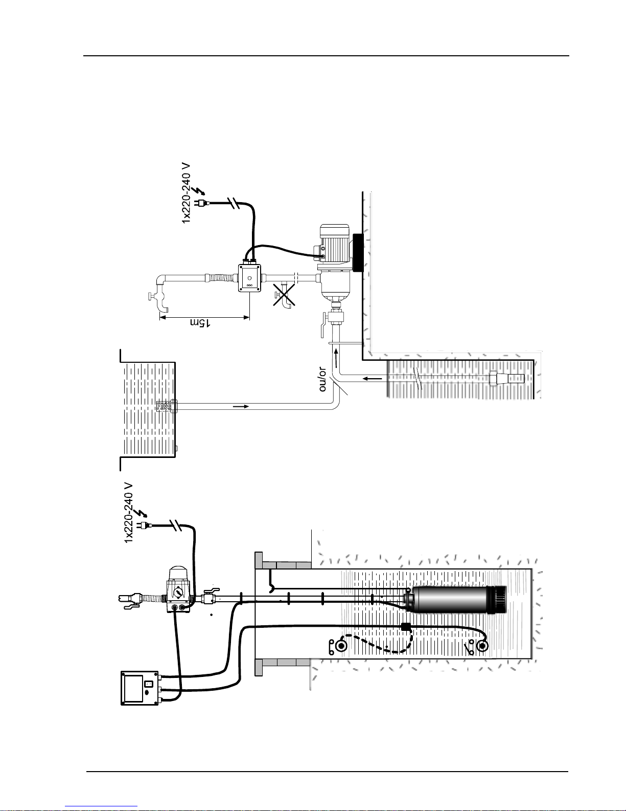
Fig. 2
Fig. 2
Page 4
220-240 V
50 - 60 Hz
M
1
L1
Fig. 4
N
U
V
Fig. 5
7
Page 5

Einbau- und
Betriebsanleitung
Installation and
operating instructions
Notice de montage et
de mise en service
Inbouw- en
gebruikshandleiding
……..6
……12
……18
……24
D
GB
F
NL
Instrucciones de instalación y
funcionamiento
Istruzioni di montaggio, uso e
manutenzione
Beépítési és
üzemeltetési útmutató
Οδηγίες εγκατάστασης
και λειτουργίας
……30
……36
……42
……48
E
I
H
GR
Page 6

ENGLISH
1 General
Installation and service by qualified personnel only!
1.1 Application
The electronic control system Wilo-Fluidcontrol (... EK) can be screw-attached
to water supply and pressure booster pumps. It enables the automatic
operation of these pumps without use of a separate pressure vessel.
Product Information
1.2
1.2.1 Technical Data
Flow medium
Max. capacity
Max. working pressure
Switch on pressure
Max. water temperature:
Power supply:
F.L.C.
Enclosure:
Connections suction/discharge
clean water free of suspended matter
10 m3/h
10 bar
1.5 - 2.7 bar
60° C
Single phase
max. 10 A
IP 65
1" BSP
1~ 220-250V,
50-60 Hz
The shut-off head generated by the applicable pump must be approx. 0.5 bar
higher than the 2.2 bar switch-off pressure.
State all name plate data when ordering spare parts.
2 Safety Notes
These instructions contain basic rules on safety which must be strictly adhered
to on installation and operation. It is therefore imperative for the Installer and
the Operator to read these instructions prior to installation and commissioning.
Please observe, not only the general safety references listed under the main
heading SAFETY NOTES, but also those added to and specially highlighted
under the ensuing headers.
12 (55)
Page 7

ENGLISH
2.1 Safety symbols contained herein
Safety notes contained herein which, if not strictly adhered to, may cause injury
to persons are specially highlighted by general danger symbol:
Warnings from electrical causes by the special symbol:
Safety references which, if not complied with, may result in damage to the plant
or its function are marked by the word:
ATTENTION!
2.2 Trade Qualifications
Only suitably qualified personnel may work on this equipment.
2.3 Hazards arising from non-compliance with safety notes
Non compliance with safety notes may cause bodily harm to persons or
damage to the plant. Failure to comply with safety notes may invalidate any
damage claims. Non-compliance may, for example, lead to the following
hazardous consequences:
● failure of vital plant functions,
● hazards to persons due to electrical and/or mechanical causes.
2.4 Safety notes for the Operator
Local regulations regarding the prevention of accidents must be observed.
Hazards from electrical energy must be excluded (conforming to local or
general regulations such as EC, BSI, UL, VDE, etc.).
2.5 Safety rules for inspections and installation work.
It is the Operator's responsibility to ensure that inspection and installation
works are carried out by authorized and qualified personnel only, after
having made themselves fully conversant with these instructions.
Work on this plant must on principle be carried out with the plant switched off
and completely pressure-relieved.
The safety valve must not be removed.
2.6 Arbitrary alterations and spare part procurement
Any alterations to the plant are only permitted with the manufacturers' consent.
Original and manufacturer authorized spare parts serve safety. The use of
other parts can invalidate any claims for consequential damages.
13 (55)
Page 8

ENGLISH
2.7 Non-permissible operating conditions
Operational safety of the plant is conditional on it being used in accordance
with Chapter 1 of these instructions. Operational criteria must not exceed or
fall short of the limits stated in catalogue/data sheets.
3 Transport and Storage
ATTENTION!
During transport and intermediate storage it is necessary
to protect the WILO-Fluidcontrol from moisture and
mechanical damage.
The stock location must be dry and be frost-free.
4 Description of the Product
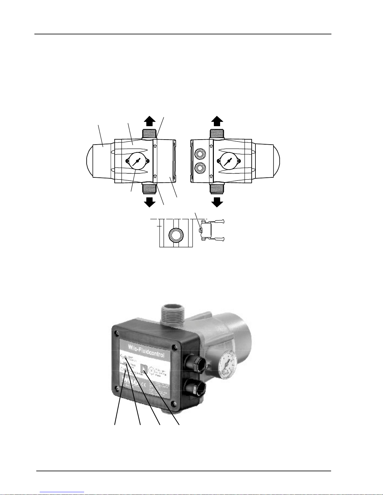
4.1 Description of the Device (Fig. 1 & 2)
1. Suction port with integrated non-return valve
2. Delivery port
3. Pressure gauge (0-10 bars) for control – possible mounting on right or left
side.
4. Electric box with electronic board including a protection against dry
running with motor stop and connection box for pump and network.
5. Hydraulic chamber with diaphragm.
6. Compensating chamber with spring.
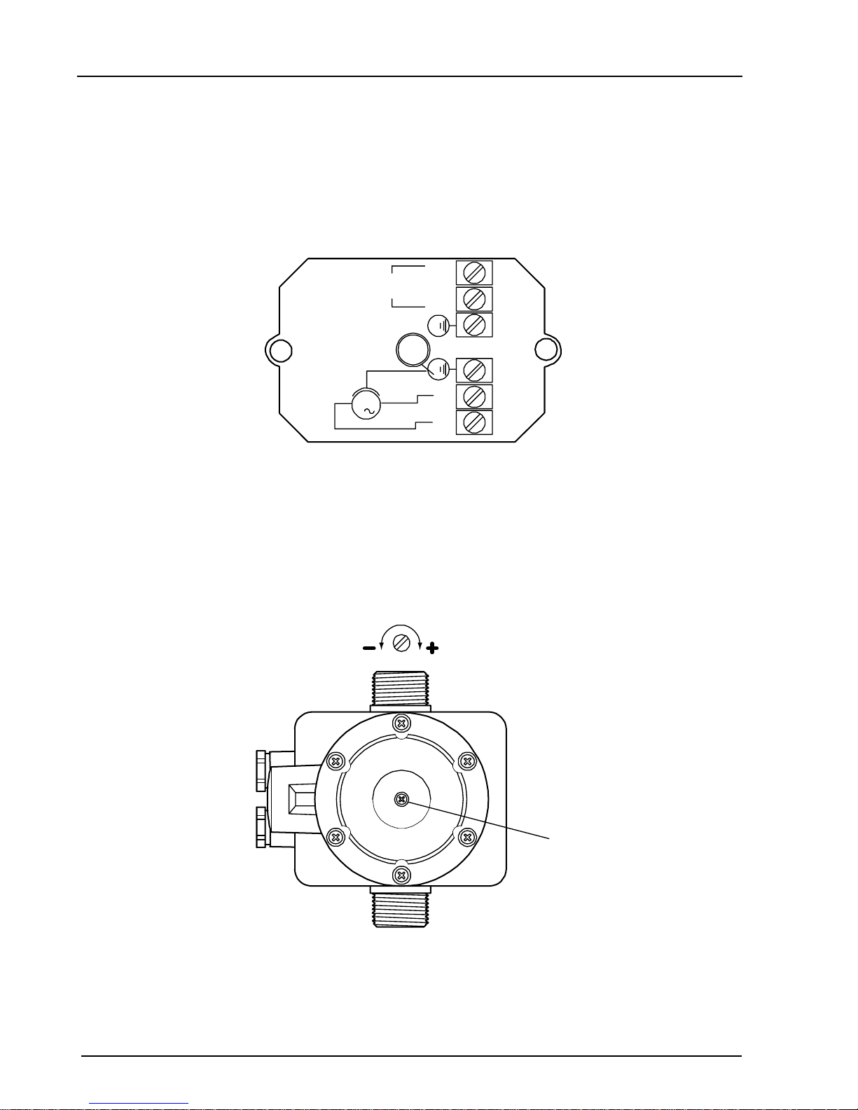
7. Adjusting screw for starting pressure of the pump.
8. Reset button (Störungs-quittierung/Reset).
9. Indicator light of the voltage (Netz/Power on).
10. Indicator light for pump running (Pumpe in Betrieb/Pump on).
11. Indicator light for activating the safety device (Störung/Failure)
12. Pressure gauge axis
The WILO-Fluidcontrol is offered as ancilliary equipment for WILO water
supply pumps.
The unit must be screwed onto the pump or into the discharge pipe. It is of
Inline design, with both connections axially in line.
On ready standby, with all outlet fitting closed and under max. system pressure,
the yellow LED is on (pos. 9).
The unit contains a small buffer space filled with water which can be varied by
means of a spring-tensioned diaphragm. If an outlet tap in the system is
opened water will flow out of the small buffer volume into the discharge pipe,
lifting the float.
14 (55)
Page 9

ENGLISH
The green diode (pos. 10) indicates normal pump operation.
The switch unit contains the electronic as well as the terminal block for power
supply and pump motor. The signal/operating elements at the switchbox cover
are (Fig. 2)
● Yellow LED: Mains power is on, the pump is on ready standby, (pos. 9)
● Green LED: Pump runs, (pos. 10)
● Red LED: Any fault leading to pressure loss in the
pipe system, (pos. 11)
● Reset button: After fault rectification the reset button (pos. 8) must be kept
pushed until the system is fully pressurized. This is also valid for renewed
start-up, otherwise the pump will again fail due to insufficient system
pressure.
4.2 Scope of Supply
● Wilo-Fluidcontrol (EK-series + integrated socket + 1.5 m connecting
cable).
● Installation and Operating Instructions.
5 Siting/Installation
5.1 Installation
For installation and mounting requirements refer to the pump installation and
operating instructions.
The arrow at the housing indicates direction of flow.
The WILO-Fluidcontrol must only be mounted into a vertically run discharge
pipe.
● The WILO-Fluidcontrol to be screwed onto the discharge port of the pump
using
suitable connecting fittings, to be sealed with hemp or Teflon band.
● If the water column between pump and highest outlet tap exceeds 15 m,
the unit must be installed at a higher level in the discharge pipe ensuring
a maximum vertical head onto the unit of not more than 15 m. In such
case no outlet tap must be located at a level below that of the WILOFluidcontrol (Fig. 3).
● In order to avoid noise transmission from the pump onto the pipe system
it is recommended to provide and install a flexible connector at the
discharge side of theWILO-Fluidcontrol.
15 (55)
Page 10

ENGLISH
5.2 Electrical Wiring
All electrical site works to be carried out by qualified and
locally licenced electricians strictly in accordance with locally
● Check available power supply,
● take note of pump name plate data requirements,
● power wiring 3 x 1.5 mm". (Minimum cable size 6 mm, maximum 9 mm
OD).
● To ensure water tightness and pull-force relief from the cable glands the
power
cable must be of sufficient outside diameter (e.g. 05 VV-F 3 (7) G 1,5
oder AVMH-I 3 (7) x 1,5).
● All electrical wiring to be executed according to Fig.4.
● Supply side fuse: see as for pump; maximum however 10 A, inert.
ruling regulations.
● Strictly adhere to local earthing regulations.
● If required (see VDE 0100), a ground fault circuit interruptor (GFCI)switch
must be provided and installed by others.
6 Commissioning
For possibly required prestart and commissioning procedures for the pump
refer to the separate installation and Operating Instruction for the pump.
Before initial start-up it must be ensured that sufficient suction capability is
available and that the pump is primed and filled.
On initial start-up the pump will run for 8 seconds, after that a renewed start-up
can be effected by keeping the reset button pushed.
7 Maintenance
Warning!
Electrical Shock Hazard!
Prior to maintenance or repair work turn off the pump and
ensure that it is not turned on by unauthorised personnel.
16 (55)
Page 11

ENGLISH
8 Faults, Causes
Fault Unit-related Cause Unit-unrelated Cause
Pump does not start - defect printed circuit board
- defect diaphragm
Pump does not stop - defect printed circuit board
- jammed flow controller - stuck
reset button
- Pump does not generate sufficient
pressure
Pump runs irregularly - defekt printed circuit board
- Pump does not generate sufficient
pressure (air)
Pump is jammed - defect printed circuit board
- pump generates pressure < start
pressure
- defect diaphragm
- refer to Installation & Maintenance
Instr. of the pump
- Power failure
- Pump capacity too low
- Pump mechanically jammed
- WILO-Fluidcontrol wrongly
connected
- Lack of water at suction side
- Leakage loss greater than 0.6
l/min
- Leakage loss greater than 0.6
l/min
- Lack of water at suction side
- Pump capacity too low
If the fault cannot be located or rectified, please contact your nearest
Wilo representative.
Technical modifications reserved!
17 (55)
Page 12

WILO AG
Nortkirchenstraße 100
44263 Dortmund
Germany
T +49 231 4102-0
F +49 231 4102-7363
www.wilo.com
Algeria
Bad Ezzouar, Dar El
Beida
T +213 21 247979
chabane.hamdad@
salmson.fr
Armenia
375001 Yerevan
T +374 10 544336
info@wilo.am
Bosnia and
Herzegovina
71000 Sarajevo
T +387 33 714510
zeljko.cvjetkovic@
wilo.ba
Georgia
0177 Tbilisi
T +995 32317813
info@wilo.ge
Macedonia
1000 Skopje
T +389 2 3122058
valerij.vojneski@
wilo.com.mk
Moldova
2012 Chisinau
T +373 2 223501
sergiu.zagurean@wilo.md
Rep. Mongolia
Ulaanbaatar
T +976 11 314843
wilo@magicnet.mn
Tajikistan
734025 Dushanbe
T +992 37 2232908
farhod.rahimov@wilo.tj
Turkmenistan
744000 Ashgabad
T +993 12 345838
wilo@wilo-tm.info
Uzbekistan
700046 Taschkent
sergej.arakelov@wilo.uz
January 2008
Wilo – International (Subsidiaries)
Wilo – International (Representation offices)
Argentina
WILO SALMSON
Argentina S.A.
C1270ABE Ciudad
Autónoma de Buenos
Aires
T +54 11 43015955
info@salmon.com.ar
Austria
WILO Handelsges.
m.b.H.
1230 Wien
T +43 5 07507-0
office@wilo.at
Azerbaijan
WILO Caspian LLC
1065 Baku
T +994 12 5962372
info@wilo.az
Belarus
WILO Bel OOO
220035 Minsk
T +375 17 2503393
wilobel@wilo.by
Belgium
WILO SA/NV
1083 Ganshoren
T +32 2 4823333
info@wilo.be
Bulgaria
WILO Bulgaria Ltd.
1125 Sofia
T +359 2 9701970
info@wilo.bg
Canada
WILO Canada Inc.
Calgary, Alberta T2A 5L4
T +1 403 2769456
bill.lowe@wilo-na.com
China
WILO China Ltd.
101300 Beijing
T +86 10 80493900
wilobj@wilo.com.cn
Croatia
WILO Hrvatska d.o.o.
10090 Zagreb
T +38 51 3430914
wilo-hrvatska@wilo.hr
Czech Republic
WILO Praha s.r.o.
25101 Cestlice
T +420 234 098711
info@wilo.cz
Denmark
WILO Danmark A/S
2690 Karlslunde
T +45 70 253312
wilo@wilo.dk
Estonia
WILO Eesti OÜ
12618 Tallinn
T +372 6509780
info@wilo.ee
Finland
WILO Finland OY
02330 Espoo
T +358 207401540
wilo@wilo.fi
France
WILO S.A.S.
78390 Bois d'Arcy
T +33 1 30050930
info@wilo.fr
Great Britain
WILO (U.K.) Ltd.
DE14 2WJ BurtonUpon-Trent
T +44 1283 523000
sales@wilo.co.uk
Greece
WILO Hellas AG
14569 Anixi (Attika)
T +302 10 6248300
wilo.info@wilo.gr
Hungary
WILO Magyarország
Kft
2045 Törökbálint
(Budapest)
T +36 23 889500
wilo@wilo.hu
Ireland
WILO Engineering Ltd.
Limerick
T +353 61 227566
sales@wilo.ie
Italy
WILO Italia s.r.l.
20068 Peschiera
Borromeo (Milano)
T +39 25538351
wilo.italia@wilo.it
Kazakhstan
WILO Central Asia
050002 Almaty
T +7 3272 785961
in.pak@wilo.kz
Korea
WILO Pumps Ltd.
621-807 Gimhae
Gyeongnam
T +82 55 3405800
wilo@wilo.co.kr
Latvia
WILO Baltic SIA
1019 Riga
T +371 7 145229
mail@wilo.lv
Lebanon
WILO SALMSON
Lebanon
12022030 El Metn
T +961 4 722280
wsl@cyberia.net.lb
Lithuania
WILO Lietuva UAB
03202 Vilnius
T +370 5 2136495
mail@wilo.lt
The Netherlands
WILO Nederland b.v.
1948 RC Beverwijk
T +31 251 220844
info@wilo.nl
Norway
WILO Norge AS
0901 Oslo
T +47 22 804570
wilo@wilo.no
Poland
WILO Polska Sp. z.o.o.
05-090 Raszyn
T +48 22 7026161
wilo@wilo.pl
Portugal
Bombas Wilo-Salmson
Portugal Lda.
4050-040 Porto
T +351 22 2080350
bombas@wilo.pt
Romania
WILO Romania s.r.l.
077040 Com. Chiajna
Jud. Ilfov
T +40 21 3170164
wilo@wilo.ro
Russia
WILO Rus ooo
123592 Moscow
T +7 495 7810690
wilo@orc.ru
Saudi Arabia
WILO ME - Riyadh
Riyadh 11465
T +966 1 4624430
wshoula@wataniaind.com
Serbia and
Montenegro
WILO Beograd d.o.o.
11000 Beograd
T +381 11 2850242
office@wilo.co.yu
Slovakia
WILO Slovakia s.r.o.
82008 Bratislava 28
T +421 2 45520122
wilo@wilo.sk
Slovenia
WILO Adriatic d.o.o.
1000 Ljubljana
T +386 1 5838130
wilo.adriatic@wilo.si
South Africa
Salmson South Africa
1610 Edenvale
T +27 11 6082780
errol.cornelius@
salmson.co.za
Spain
WILO Ibérica S.A.
28806 Alcalá de
Henares (Madrid)
T +34 91 8797100
wilo.iberica@wilo.es
Sweden
WILO Sverige AB
35246 Växjö
T +46 470 727600
wilo@wilo.se
Switzerland
EMB Pumpen AG
4310 Rheinfelden
T +41 61 8368020
info@emb-pumpen.ch
Taiwan
WILO-EMU
Taiwan Co. Ltd.
110 Taipeh
T +886 227 391655
nelson.wu@
wiloemutaiwan.com.tw
Turkey
WILO Pompa Sistemleri
San. ve Tic. A.S¸.
34530 Istanbul
T +90 216 6610211
wilo@wilo.com.tr
Ukraina
WILO Ukraina t.o.w.
01033 Kiew
T +38 044 2011870
wilo@wilo.ua
Vietnam
Pompes Salmson
Vietnam
Ho Chi Minh-Ville
Vietnam
T +84 8 8109975
nkm@salmson.com.vn
United Arab Emirates
WILO ME - Dubai
Dubai
T +971 4 3453633
info@wilo.com.sa
USA
WILO-EMU USA LLC
Thomasville,
Georgia 31792
T +1 229 5840097
info@wilo-emu.com
USA
WILO USA LLC
Melrose Park,
Illinois 60160
T +1 708 3389456
mike.easterley@
wilo-na.com
Page 13

WILO AG
Nortkirchenstraße 100
44263 Dortmund
Germany
T 0231 4102-0
F 0231 4102-7363
wilo@wilo.de
www.wilo.de
G1 Nord
WILO AG
Vertriebsbüro Hamburg
Beim Strohhause 27
20097 Hamburg
T 040 5559490
F 040 55594949
hamburg.anfragen@wilo.de
G2 Ost
WILO AG
Vertriebsbüro Berlin
Juliusstraße 52–53
12051 Berlin-Neukölln
T 030 6289370
F 030 62893770
berlin.anfragen@wilo.de
G3 Sachsen/Thüringen
WILO AG
Vertriebsbüro Dresden
Frankenring 8
01723 Kesselsdorf
T 035204 7050
F 035204 70570
dresden.anfragen@wilo.de
G4 Südost
WILO AG
Vertriebsbüro München
Landshuter Straße 20
85716 Unterschleißheim
T 089 4200090
F 089 42000944
muenchen.anfragen@wilo.de
G5 Südwest
WILO AG
Vertriebsbüro Stuttgart
Hertichstraße 10
71229 Leonberg
T 07152 94710
F 07152 947141
stuttgart.anfragen@wilo.de
G6 Rhein-Main
WILO AG
Vertriebsbüro Frankfurt
An den drei Hasen 31
61440 Oberursel/Ts.
T 06171 70460
F 06171 704665
frankfurt.anfragen@wilo.de
G7 West
WILO AG
Vertriebsbüro Düsseldorf
Westring 19
40721 Hilden
T 02103 90920
F 02103 909215
duesseldorf.anfragen@wilo.de
Kompetenz-Team
Gebäudetechnik
WILO AG
Nortkirchenstraße 100
44263 Dortmund
T 0231 4102-7516
T 01805 R•U•F•W•I•L•O*
7•8•3•9•4•5•6
F 0231 4102-7666
Kompetenz-Team
Kommune
Bau + Bergbau
WILO EMU GmbH
Heimgartenstraße 1
95030 Hof
T 09281 974-550
F 09281 974-551
Werkskundendienst
Gebäudetechnik
Kommune
Bau + Bergbau
Industrie
WILO AG
Nortkirchenstraße 100
44263 Dortmund
T 0231 4102-7900
T 01805 W•I•L•O•K•D*
9•4•5•6•5•3
F 0231 4102-7126
Erreichbar Mo–Fr von
7–17 Uhr.
Wochenende und feiertags 9–14 Uhr elektronische Bereitschaft mit
Rückruf-Garantie!
– Kundendienst-
Anforderung
– Werksreparaturen
– Ersatzteilfragen
– Inbetriebnahme
– Inspektion
– Technische Service-
Beratung
– Qualitätsanalyse
Wilo-International
Österreich
Zentrale Wien:
WILO
Handelsgesellschaft mbH
Eitnergasse 13
1230 Wien
T +43 5 07507-0
F +43 5 07507-15
Vertriebsbüro Salzburg:
Gnigler Straße 56
5020 Salzburg
T +43 5 07507-13
F +43 5 07507-15
Vertriebsbüro
Oberösterreich:
Trattnachtalstraße 7
4710 Grieskirchen
T +43 5 07507-26
F +43 5 07507-15
Schweiz
EMB Pumpen AG
Gerstenweg 7
4310 Rheinfelden
T +41 61 8368020
F +41 61 8368021
Standorte weiterer
Tochtergesellschaften
Argentinien, Aserbaidschan,
Belarus, Belgien, Bulgarien,
China, Dänemark, Estland,
Finnland, Frankreich,
Griechenland, Großbritannien,
Irland, Italien, Kanada,
Kasachstan, Korea, Kroatien,
Lettland, Libanon, Litauen,
Niederlande, Norwegen,
Polen, Portugal, Rumänien,
Russland, Saudi-Arabien,
Schweden, Serbien und
Montenegro, Slowakei,
Slowenien, Spanien,
Südafrika, Taiwan,
Tschechien, Türkei, Ukraine,
Ungarn, Vereinigte Arabische
Emirate, Vietnam, USA
Die Adressen finden Sie
unter www.wilo.de oder
www.wilo.com.
Stand Januar 2008
Wilo-Vertriebsbüros in Deutschland
Erreichbar Mo–Fr von 7–18 Uhr.
– Antworten auf
– Produkt- und Anwendungsfragen
– Liefertermine und Lieferzeiten
– Informationen über Ansprechpartner vor Ort
– Versand von Informationsunterlagen
* 14 Cent pro Minute aus dem deutschen Festnetz
der T-Com. Bei Anrufen aus Mobilfunknetzen
sind Preisabweichungen möglich.
 Loading...