

Page 1
Einbau- und Betriebsanleitung
Installation and Operating Instructions
Notice de montage et de mise en service
Onderhouds- en bedieningsvoorschrift
Wilo-FilTec FBS
D
GB
F
NL
2018538/2000.09.DDD
Page 2
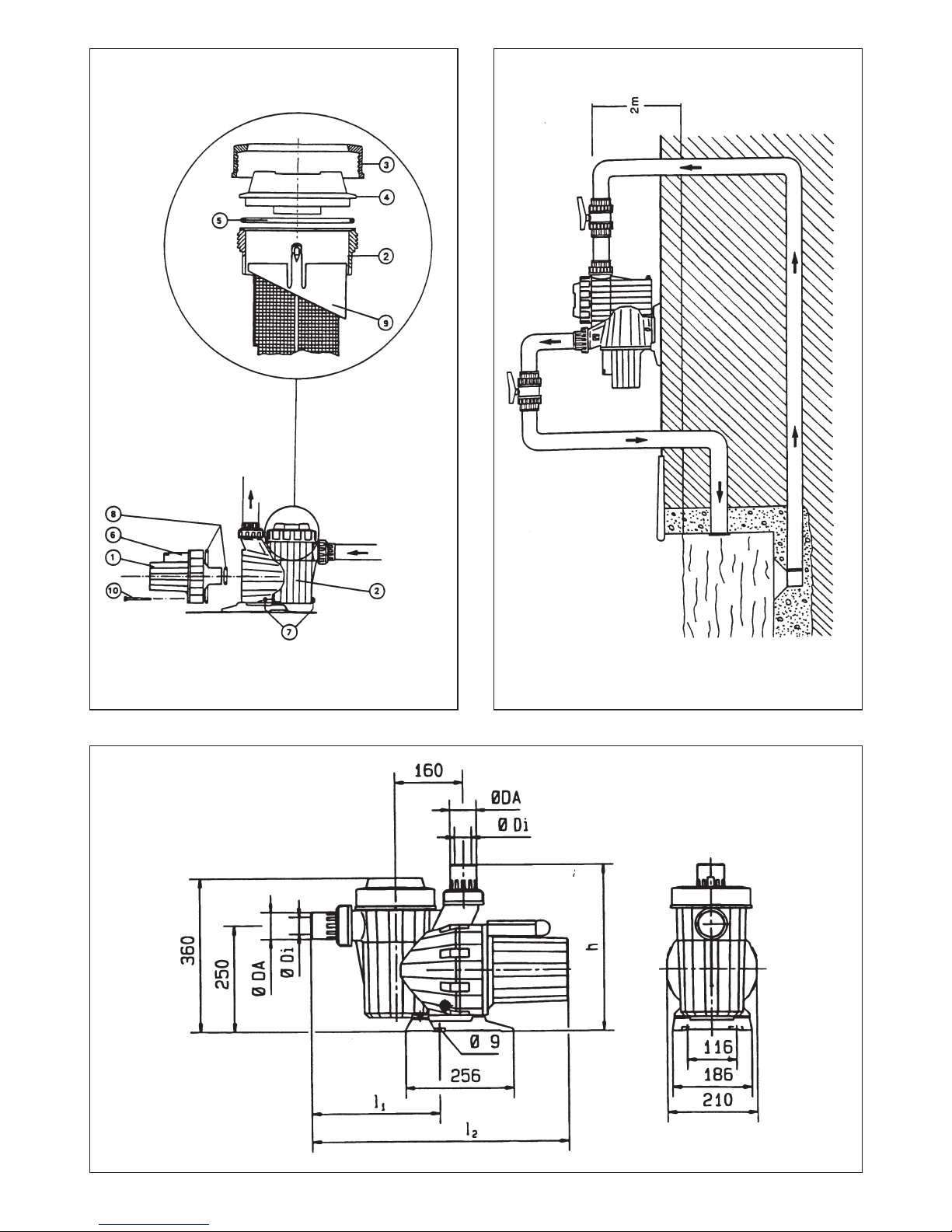
Fig. 1
Fig. 2
Fig. 2a
Page 3
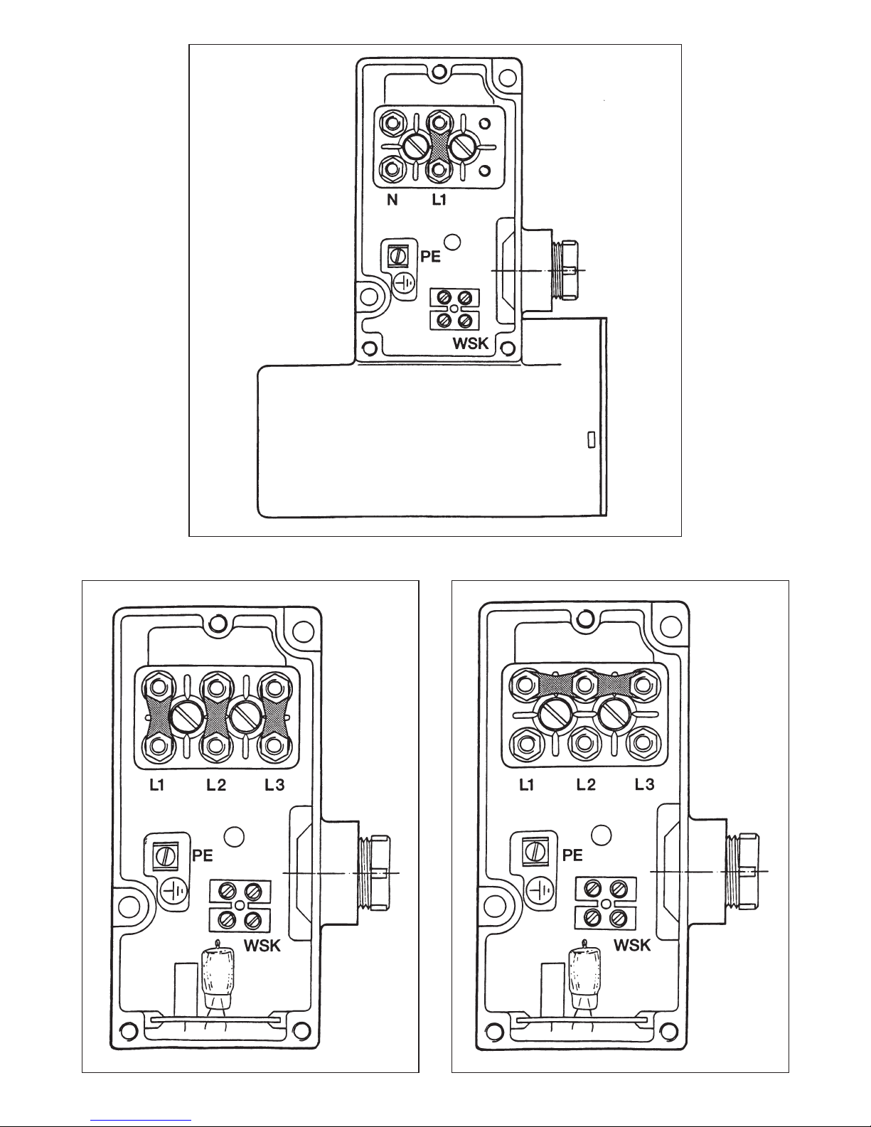
Fig. 5Fig. 4
Fig. 3
Page 4

Bei Sicherheitshinweisen, deren Nichtbeachtung
Gefahren für die Maschine und deren Funktion hervorrufen können, ist das Wort
eingefügt.
2.2 Personalqualifikation
Das Personal für die Montage muß die entsprechende Qualifikation für diese Arbeiten aufweisen.
2.3 Gefahren bei Nichtbeachtung der
Sicherheitshinweise
Die Nichtbeachtung der Sicherheitshinweise kann
eine Gefährdung für Personen und Filterpumpe zur
Folge haben. Die Nichtbeachtung der Sicherheitshinweise kann zum Verlust jeglicher Schadenersatzansprüche führen.
Im einzelnen kann Nichtbeachtung beispielsweise
folgende Gefährdungen nach sich ziehen:
– Versagen wichtiger Funktionen der Pumpe/
Anlage,
– Gefährdungen von Personen durch elektrische
und mechanische Einwirkungen.
2.4 Sicherheitshinweise für den Betreiber
Die bestehenden Vorschriften zur Unfallverhütung
sind zu beachten.
Gefährdungen durch elektrische Energie sind auszuschließen. Vorschriften des VDE und der örtlichen Energieversorgungsunternehmen beachten.
2.5 Sicherheitshinweise für Inspektions- und
Montagearbeiten
Der Betreiber hat dafür zu sorgen, daß alle
Inspektions- und Montagearbeiten von autorisiertem und qualifiziertem Fachpersonal ausgeführt
werden, das sich durch eingehendes Studium der
Betriebsanleitung ausreichend informiert hat.
Grundsätzlich dürfen Arbeiten an der Filterpumpe
nur im Stillstand durchgeführt werden.
2.6 Eigenmächtiger Umbau und
Ersatzteilherstellung
Veränderungen der Filterpumpe sind nur nach
Absprache mit dem Hersteller zulässig. Originalersatzteile und vom Hersteller autorisiertes
Zubehör dienen der Sicherheit. Die Verwendung
anderer Teile kann die Haftung für die daraus entstehenden Folgen aufheben.
2.7 Unzulässige Betriebsweisen
Die Betriebssicherheit der gelieferten Filterpumpe
ist nur bei bestimmungsgemäßer Verwendung
entsprechend Abschnitt 1 der Betriebsanleitung
gewährleistet. Die im Datenblatt angegebenen
Grenzwerte dürfen auf keinen Fall überschritten
werden.
3 Transport und Zwischenlagerung
Die Filterpumpe ist von außen gegen
Feuchtigkeit zu schützen!
4 Beschreibung des Erzeugnisses
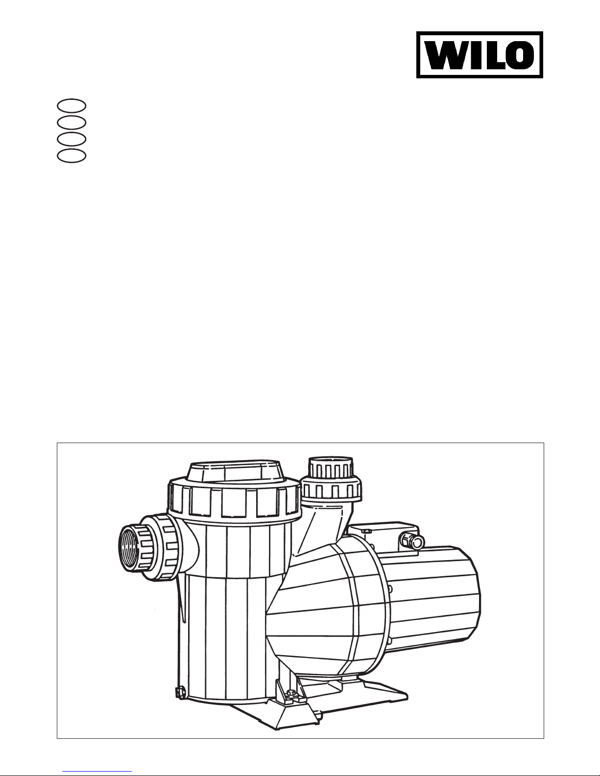
4.1 Beschreibung der Filterpumpe (Bild 1)
Das Pumpengehäuse besteht aus einem glasfaserverstärkten Kunststoff für den Einsatz im
Schwimmbad. Die Pumpe ist mit einem Naßläufermotor in Wechsel- oder Drehstromausführung ausgerüstet und ist selbstansaugend.
Vor der Pumpe ist ein Grobfilter angeordnet, der
sicherstellt, daß die Pumpe nicht durch grobe
Verunreinigungen verstopft wird. Ein serienmäßiger
Wicklungsschutzkontakt (WSK) bewahrt die Pumpe vor Beschädigung bei Überlastung. Der WSK ist
aber nur in Verbindung mit einem entsprechenden
Schaltgerät/-kasten wirksam.
Die Pumpe saugt das Schwimmbadwasser z.B.
über den Oberflächen-Absauger (Skimmer) an und
pumpt es über den Filter gereinigt wieder ins
Schwimmbecken zurück. Oberflächen-Absauger
(Skimmer) und Filter sind bauseitig beizustellen.
4.2 Lieferumfang
– Filterpumpe
– 2 Übergangsstücke mit Überwurfmuttern und
Flachdichtungen:
für FBS 10 und 15: l 50 x 40 mm,
für FBS 20 und 25: l 63 x 74 mm
– vorgeschalteter integrierter Vorfilter
– Filterkorb im Vorfilter
– Ringschlüssel zum Lösen des Grobfilterdeckels
– Einbau- und Betriebsanleitung
5 Aufstellung/Einbau
– Typenschilddaten beachten.
5.1 Montage
– Die Filterpumpe ist waagerecht einzubauen.
– Vor und hinter der Pumpe sollten Absperr-
armaturen eingebaut werden, um einen evtl.
Pumpenaustausch zu erleichtern. Dabei ist die
Montage so durchzuführen, daß evtl. Leckwasser
nicht auf die Pumpe tropfen kann.
– Saug- und Druckleitung aus PVC mit den Über-
gangsstücken der Pumpe verkleben:
für FBS 10 und 15: Rohrleitung wird in das Über-
gangsstück gesteckt,
ACHTUNG!
ACHTUNG!
DEUTSCH
4
Page 5

für FBS 20 und 25: Rohrleitung wird über das
Übergangsstück geschoben.
– Anschließend die Anschlußleitungen mit der
Pumpe verschrauben (Flachdichtungen einlegen).
Die Überwurfmuttern haben ein Sondergewinde. Keine anderen Verschraubungen benutzen!
– Die Anschlußrohre müssen spannungsfrei mit
der Pumpe verbunden sein.
5.1.1 Aufstellungshinweise
- Einbaumaße und Anschlußgrößen sind der
Tabelle 2 im Absatz 1.2.1 und Maßzeichnung zu
Tabelle 2 zu entnehmen.
– Die Pumpe kann, vom Sauganschluß gemessen,
bis 5 m unter und bis 2 m über dem Wasserspiegel aufgestellt werden (Bild 2).
– Das zweckmäßigste Aufstellungsniveau ist unter-
halb der Wasseroberfläche. Die Pumpe kann
dann im Zulaufbetrieb arbeiten (sie braucht
keine Saugarbeit zu leisten).
– Grundsätzlich sind die Saugleitungen so kurz
wie möglich auszuführen.
– Muß die Pumpe oberhalb des Wasserspiegels
aufgestellt werden, sollte die Saugleitung (vom
Becken zur Pumpe) möglichst in voller Länge
unterhalb des Wasserspiegels verlegt und erst
an der Filterpumpe nach oben geführt werden,
damit die Saugleitung beim Stillstand der
Filterpumpe möglichst wenig leerläuft.
– Steht die Filteranlage über dem Wasserspiegel,
und die Saugleitung ist außerdem noch lang, ist
es sinnvoll, die Umwälzpumpe getrennt von der
Filteranlage in Beckennähe und unterhalb des
Wasserspiegels aufzustellen.
– Bei Saugbetrieb sind leichte, aber gut dichtende
Rückschlagklappen im tiefsten Punkt der Saugleitung einzubauen. Sie helfen, den Wasserstand
im Saugrohr bei abgeschalteter Filteranlage zu
halten. Diese Klappen müssen jedoch zugänglich und ausbaubar sein, damit sie gereinigt werden können.
– Maximal zulässige Länge der gesamten Ring-
leitung beträgt 30 m.
5.2 Elektrischer Anschluß
5.2.1Sicherheitshinweise
Als wirksamer Schutz gegen Elektrounfälle ist der Einbau eines Fehlerstromschutzschalters (FI-Schalter) für
die gesamte Installation im Schwimm-
badbereich erforderlich. Auslösestrom
30 mA.
Die Zuleitung ist mit einem allpoligen Hauptschalter
(Kontaktöffnungsweite min. 3 mm) zu versehen.
Zur Sicherung gegen zu hohe Berührungsspannung sind alle metallischen Teile am Boden
oder am Becken mit einer Potentialausgleichsleitung (LPA) zu verbinden. Diese Leitung, Mindestquerschnitt 10 mm
2
Cu, sollte mit einer eigens
angelegten Potentialausgleichsschiene verbunden
und diese wiederum geerdet werden, z. B. mit einem Banderder, Plattenerder o.a. Separat ist diese
Ausgleichsschiene mit dem vom Netz kommenden
Schutzleiter zu verbinden.
Der Erdwiderstand der Potentialausgleichsleitung
muß kleiner sein als 800 Ohm, damit im Fehlerfall
keine höhere Berührungsspannung als 24 V auftritt.
Um die Funktion des Wicklungsschutzkontaktes
(WSK) sicherzustellen, ist bauseits ein Schaltgerät/-kasten beizustellen (Wilo-Lieferprogramm).
5.2.2 Allgemeine Hinweise
– Der elektrische Anschluß ist von einem
beim örtlichen EVU zugelassenen
Elektroinstallateur und entsprechend
den geltenden VDE-Vorschriften (VDE
0100, Teil 702) auszuführen.
– Stromart und Spannung des Netzanschlusses
überprüfen
– Typenschilddaten des anzusteuernden Pumpen-
motors beachten
– Netzseitige Absicherung: 10 A, träge
– Bodenplatte (nicht im Lieferumfang enthalten) an
der dafür vorgesehenen Erdungsschraube er-
den
– Schutzart IP 54
– Der Pumpenmotor ist mit einem Wicklungs-
schutzkontakt (WSK) ausgerüstet. Im Schalt-
gerät/-kasten der Filteranlage muß eine entspre-
chende Anschlußmöglichkeit vorhanden sein.
5.2.3 Klemmenleisten
Elektrischen Anschluß entsprechend den
Klemmenanschlußbildern ausführen.
Bild 3: Motorklemmenbrett für EM 1 Ù 230 V
Bild 4: Motorklemmenbrett für DM 3 Ù 230 V (V)
Bild 5: Motorklemmenbrett für DM 3 Ù 400V (Y)
6 Inbetriebnahme
– Schwimmbecken und, falls vorhanden, Schwall-
wasserbehälter müssen gefüllt sein.
– Alle Absperrarmaturen schließen.
ACHTUNG!
DEUTSCH
5
Page 6

– Überwurfmutter (Bild 1, Pos.3) des Grobfilter-
behälters (Bild1, Pos.2).mit dem mitgelieferten
Ringschlüssel lösen und Filterdeckel (Bild 1,
Pos.4) abnehmen.
Bei jeder Inbetriebnahme nach einer
Entleerung des Systems Grobfilterbehälter mit Wasser füllen! Im Falle
der Aufstellung der Filteranlage oberhalb des Wasserspiegels wird damit
die Selbstansaugfähigkeit der Pumpe
sichergestellt.
– Deckel mit der dazu vorgesehenen O-Ring-
Dichtung wieder auflegen und Überwurfmutter
mit dem Schlüssel handfest anziehen.
Pumpe nie ohne Grobfilter (Bild 1,
Pos.9) in Betrieb nehmen!
– Absperrarmaturen wieder öffnen.
– Pumpe bzw. Schaltgerät einschalten
– Drehrichtungskontrolle: nur bei Drehstrommotor
erforderlich. Pumpe kurz einschalten. Die auf
dem Klemmenkasten (Bild 1, Pos.6) des Motors
sichtbare Leuchtanzeige darf nicht brennen.
Leuchtet sie, so läuft der Motor in falscher
Drehrichtung. Zwei beliebige Phasen des Netzanschlusses vertauschen.
– Ist im Steuergerät eine elektronische Ab-
sicherung gegen Motorüberlastung eingebaut,
so muß das Gerät auf den Nennstrom des Motors
eingestellt werden.
– Kurzzeitiger Trockenlauf schadet der Pumpe
nicht. Sie sollte aber nicht längere Zeit ohne
Wasser laufen.
– Die weiteren Inbetriebnahme-Schritte sind der
Einbau- und Betriebsanleitung der Filteranlage
zu entnehmen.
7 Wartung / Instandhaltung
– Bei nicht frostsicher aufgestellten Filteranlagen
z.B. für Freibäder muß auch die Filterpumpe im
Winter entleert werden. Dazu sind die
Entleerungsschrauben an der Pumpe (Bild 1,
Pos.7) mit einem geeigneten Werkzeug zu öffnen. Die PVC-Schrauben können leicht beschädigt werden. Entleerungsschrauben nur handfest anziehen.
– Der Grobfilter ist von Zeit zu Zeit zu kontrollieren
und zu reinigen. Dabei die O-Ring-Dichtung und
deren Sitzfläche sauber halten (Bild 1, Pos.5).
Den Grobfilter wieder so einsetzen, daß die vorhandene Aussparung im Einsatzrand in die Nase
der Sitzfläche des Gehäuses greift. (Abschnitt 6
Inbetriebnahme beachten!)
– Bei einem Pumpendefekt: Pumpe zuerst ab-
schalten, dann kann der Motorblock (Bild1,
Pos.1) vom Pumpengehäuse durch Lösen der
acht Schrauben (Bild 1, Pos.10) getrennt werden.
Bei der Wiedermontage ist auf korrekten Sitz der
beiden O-Ring-Dichtungen (Bild 1, Pos.8) zu
achten. Schrauben über Kreuz gleichmäßig anziehen. Der Motorblock darf nur von qualifiziertem Personal demontiert und montiert werden.
Zur Aufrechterhaltung von Garantieansprüchen dürfen Reparaturarbeiten nur durch den Kundendienst des
Herstellers ausgeführt werden.
ACHTUNG!
ACHTUNG!
ACHTUNG!
DEUTSCH
6
Page 7

DEUTSCH
7
8 Störungen, Ursachen und Beseitigung
Störung Ursache Beseitigung
Pumpe füllt sich nicht Lufteintritt am Ansaugrohr Zustand der Anschlüsse, Verbindungen und
Dichtungen überprüfen
Grobfilterdeckel Grobfilterdeckel reinigen und Zustand der Oschließt nicht dicht Ring-Dichtung prüfen
Falsche Drehrichtung des 2 Phasen des Netzanschlusses vertauschen
Motors (DM-Ausführung)
Pumpe fördert zu Lufteintritt am Ansaugrohr Zustand der Anschlüsse, Verbindungen und
wenig Wasser Dichtungen überprüfen
Falsche Drehrichtung des 2 Phasen des Netzanschlusses vertauschen
Motors (DM-Ausführung)
Druckverlust beim Ansaugen Elemente, die Druckverluste verursachen,
vermeiden
Falsche Spannung Prüfen, ob Netzspannung mit der auf dem
Typenschild übereinstimmt.
Grobfilter verstopft Grobfilter reinigen
Hauptfilter verstopft Rückspülvorgang einleiten
Ausfall des Motors Phasenausfall Bei Rückkehr der Spannung stellt sich
vorheriger Betriebszusand wieder ein.
WSK des Pumpenmotors Motor abkühlen lassen, Störung am Schalt-
hat ausgelöst gerät/-kasten quittieren, Pumpe läuft wieder
an. Bei wiederholtem Auslösen des WSK muß
die Pumpe elektrisch und mechanisch über-
prüft werden.
Falls die Störung bzw. der Fehler nicht behoben werden kann, wenden Sie sich bitte an den WiloKundendienst.
Technische Änderungen vorbehalten!
Page 8

1 General
Installation and service by qualified personnel
only!
1.1 Applications
The pool circulating pumps are used in conjunctions with highrate sand filter plants for private
swimming pools. They are resistant to chemicals
normally used for pool maintenance, but not to sea
or salt water.
ENGLISH
8
1.2 Technical data
1.2.1Performance and electrical data (Table 1)
Max. permissible pressure 2,3 bar
Main voltages 1 Ù 230 V ± 10 % , 50 Hz
3 Ù 400 V ± 10 % , 50 Hz
Speed see rating plate
Capacity and current see rating plate
Flow rate and -heat see rating plate
Protective system IP 54
Haupt- und Anschlußmaße, Tabelle 2
Types dimensions [mm]
FBS DA DI h l1 l2
10 – 50 366 265 525
15 – 50 366 265 560
20 and 25 63 – 400 300 595
Resistance to chemicals are limited by the following limits:
– Max. water temperature: 40°C
– pH-value: min. 6, max. 7,8
– Free chlorine: 0.2 up to max. 2.0 mg/l (or ppm),
Short term limit e.g. for reconditioning of pool
water max. 20 ppm.
– Free chlorides: max. 250 mg/l
– The pump is not suitable to handle sea or salt
water
– Pump must not be used to handle water condi-
tioned by Sodium Hypochlorit (by electrolysis).
– Pump must not run dry.
2 Safety Notes
These instructions contain basic reference which
must be strictly adhered to. It is therefore imperative for the installer and the Operator to carefully
read these instructions prior to installation and
commissioning.
Please observe, not only the safty directions under
the main heading SAFTY RULES, but also those
added and specially marked under the ensuing headers.
2.1 Safty marks contained in these instructions
Safaty references contained here in which, if not
complied with, may cause death or severe personal injury from electrical causes are specially highlighted by the following danger symbol:
Safty refernces which, if not complied with, may result in damage to the plant or its function are highlighted by the word:
ATTENTION!
Page 9

2.2 Trade qualifications
Only qualified personnel may work on this equipment.
2.3 Dangers from non- oberservance of safety
references
Non- oberservance of safety references may cause
bodily harm to persons or damage to the filter
pump. Failure to comply with safety references
could invalidate warranty and/or damage claims. In
detail, non-compliance may, for example, cause
the following dangerous possibilities:
– failure of vital plant functions or damage to plant,
– causing personal injury due to electrical and/or
mechanical causes.
2.4 Safety refernce for the Operator
It is the Operator´s responsibility to ensure that inspections and installation work are carried out by
authorized and qualified personnel only, having
themselves made fully conversant with these instructions.
Work must principally be carried out only with the
plant switched off and at complete standstill.
2.5 Safety reference for inspections
and installation work
It is the Operator´s responsibility to ensure that inspections and installation work are carried out by
authorized and qualified personnel only, having
themselves made fully conversant with these instructions.
Work must principally be carried out only with the
plant switched off and at complete standstill.
2.6 Arbitrary alterations and spare
part procurement
Any alterations to the plant are only permitted in
agreement with the manufacturers. Original spare
parts and authorized accessories serve safety and
reliability. The use of unauthorized parts could invalidate any claims for consequential damages.
2.7 Abnormal operating conditions
Operational safety of the plant is only ensured if
used in accordance with chapter 1 of these instructions. The limits stated there must not be exceeded under any circumstances.
3 Transport and Storage
The filter pump must be externally
protected from moisture.
4 Description of Product and
Accessories
4.1 Description of the pool circulating pump
(Fig. 1)
The pump housing is constructed of glas fibre reinforced plastics for use in swimming pools. The
pump is of the canned- rotor type, self-priming and
optionally available with single or three phase motors. The inlet port is equipped with a lint strainer in
order to prevent coarse impurities entering and
jamming the pump. Standard thermal overload
contacts (WKS) prevent damage to the pump due
to excess current draw. The WSK is, however, only
effective in conjunction with an appropiate switchbox.
The pump draws water from the pool, e.g. via a
skimmer and pumps it back to the pool via the filter.
4.2 Scope of supply
– Pool circulating pump
– Two (2) connectors with union nuts, inserts and
washers
Size FBS 10 and 15: 50 diam.x40 mm,
Size FBS 20 and 25: 63 diam.x74mm
– connected integrated preliminary filter
– filter cartridge in the preliminary filter
– Ring spanner for handling the coarse strainer
cover
– Installation and Operating Instructions.
5 Siting/Installation
– observe data on the motor rating plate
5.1 Installation
– Install the pool circulating pump with the shaft in
the hotizontal plane
– Glue PVC suction and disharge pipes to pump
union connections
Size FBS 10 and 15:Pipes to be pushed into the
inside of the union inserts
Size FBS 20 and 25:Pipes to be pushed onto the
outside of the union inserts
– Screw connecting pipes onto the pump after in-
serting the washers
The union nuts have special threads.
Do not use any other kind of union
nuts.
– Connections to the pump to be done such that it
is not stressed by the pipework.
ATTENTION!
ATTENTION!
ENGLISH
9
Page 10

5.1.1 Mounting instructions
– Dimensions for installation and conections are
given in table 2 paragragh 1.2.1 and fig. 2a
– The pump can be mounted up to 5 metres below
and up to 2 metres above pool water level, measured from suction inlet connection (Fig.2).
– The most suitable mounting level is below the
pool water level. The pump then operates under
flooded suction (without suction lift).
– On priciple, suction lines should be as short as
possible.
– If it is necessary to mount the pump above pool
water level, the suction pipe (from pool to the
pump) should preferably be run full-length horizontally below water level and only rise directly
at the pump. The suction line will then, on shutdown of filter pump, only slightly be emptied.
– If the sand filter is placed above water level and
with an additionally long suction run, the circulating pump should preferably be mounted seperate from the filter close to the pool below water
level.
– When operating with a suction lift, light-weight
but positively sealing non-return valve should be
fitted at the lowest point of the suction line. They
will assist in maintaining the water level in the
suction line during standstill of the filter plant.
These checkvalves must, for the ease of cleaning, be easily accessible and removable.
– Total lengths of the circulating pipework must not
exceed 30 metres.
5.2 Electrical wiring
5.2.1 Safety information
As an effective protection against disastrous effects of earth fault currents it is
required to install an earth fault circuit
interruptor (Fl-switch) for the total electrical circutery of the pool system. Trip
current 30mA.
An all-pole isolation switch (min.contact gap 3mm)
must be installed in the power supply cable.
As an protection from excessively high shock voltage it is required to connect all metallic parts at
pool bottom and walls with a potential compensation wiring. This copper wire, minimum size 10 mm
2
CU, should be conncted to a specially set and earthed potential compensating busbar, which is to be
seperately connected to the earth wire of the power
supply.
The earthing resistance of the potential compensating wire must be less than 800 ohms in order to
restrict the shock voltage to less than 24 V in case
of a fault.
A switchbox must be provided on site by others to
ensure the thermall overload contacts (WSK) of the
pump motor to be effective.
5.2.2 General information
– Electrical work to be carried out by
qualified and licensed electricians in
strict conformity to ruling national stan-
dards and local regulations..
– Check available power supply data
– Observe pump name plate data
– Power supply fuses: 10A, inert action
– Baseplate (on site by others) to be earthed
– Degree of protection: IP 54
– The pump motor is internally equipped with ther-
mal overload contacts (WSK). Ensure that repective terminals are available in the filter switchbox.
5.2.3 Terminals
Effect on-site wiring according to the wiring diagrams:
Fig. 3: Motor terminal block for single phase230/240V
Fig. 4: Motor terminal block for three phase- 230V
(V)
Fig. 5: Motor terminal block for three phase400/415V (Y)
6 Commissioning (Fig.1)
– Pool and balance tank (if applicable) must be fil-
led
– Close all insolating valves
– Undo cover nut (Item 3) of the lint strainer (Item
2) with the aid of the ring spanner provided and
remove strainer cover (Item 4).
Lint strainer must be filled with after
draining the pipe system. This ensures priming ability of the pump in
case of filter plant installation above
pool water level.
– Reposition of lint strainer cover and secure by
tightening with the ring spanner.
Pump must never be run without the
lint strainer (Item 9)!
– Open isolating valves.
– Switch on pump or switchbox respectively.
– Direction of rotation check: Only required in the
case of three phase motors. Briefly switch-on
pump. The pilot light on the terminal box (Item 6)
must be off. If it is on, the pump rotates in the
ATTENTION!
ATTENTION!
ENGLISH
10
Page 11

wrong direction. Then, change any two phases
wires of the power supply.
– If using switchgear with integral electronic over-
load control, it must be adjusted to the full load
current value of the motor.
– Short- term dry- running does not damage the
pump; prolonged dry- running must, however, be
avoided.
– Further steps on plant commissioning in accor-
dance with the Operating Instructions of the
sand filter plant.
7 Maintenance (Fig. 1)
– If not located in a frost- free location (e.g. open-
air pools), ensure that circulating pumps are
drained during winter together with the filter
plant. This is done by undoing the drain plugs at
the pump (Item 7) with the aid of a suitable tool.
The PVC screws are prone to damage. Drain
plugs to be fastened hand-tight only.
– The lint strainer must be checked and cleaned
from time to time. The O-ring gasket and its seat
must be kept clean (Item 5). The filter basket
must be repositioned such that the groove at the
top ring fits the locating knob in the seating of the
strainer housing (obseve Chapter 6, Commissioning).
– In the case of a pump failure, first switch-off the
motor; the stator housing (Item 1) can then be separated from the pump housing by undoing and
removing the eight (8) holding -down screws
(Item 10). When re-assembling, ensure correct
seating of the two (2) O-ring washers (Item 8).
Screws to be tightened cross- wise. Removal
and re- assembly of the stator housing must only
be done by qualified personnel.
In order to maintain warranty claims,
repairs must only be effected by
WILO- authorized service.
ATTENTION!
ENGLISH
11
Page 12

ENGLISH
12
8 Fault finding- Causes and Remedies
If the faults cannot be located and rectified, please contact your nearest Wilo representative.
Technical modifications reserved!
Fault Cause Remedy
Pump does not fill Air entry in suction pipe Check condition of pipe, connections,
and seals.
Cover of lint strainer does Clean strainer cover and check condition
not seal tight of O-ring washer.
Wrong direction of motor Change any two phase wires.
rotation (3-phase motor)
Insufficient pump Air entry in suction pipe Check condition of pipe , connections,
performance and seals.
Wrong direction of motor Change any two phase wires.
rotation (3-phase motor)
Pressure loss in suction Eliminate any element causing excessive
pipe resistance.
Wrong voltage Check that available voltage corresponds
with name plate data.
Chocked lint strainer Clean lint strainer
Chocked main sand filter Start backwash cycle.
Motor failure Loss of phase The original operating conditions are
automatically restored on power restoration.
WSK of pump motor has Let motor cool down, reset fault at switchbox,
tripped pump will restart. On repeated tripping of the
WSK it will be necessary to check pump
electrically and mechanically.
 Loading...