

Wilmont Grinders TAG 101 Assembly Manual
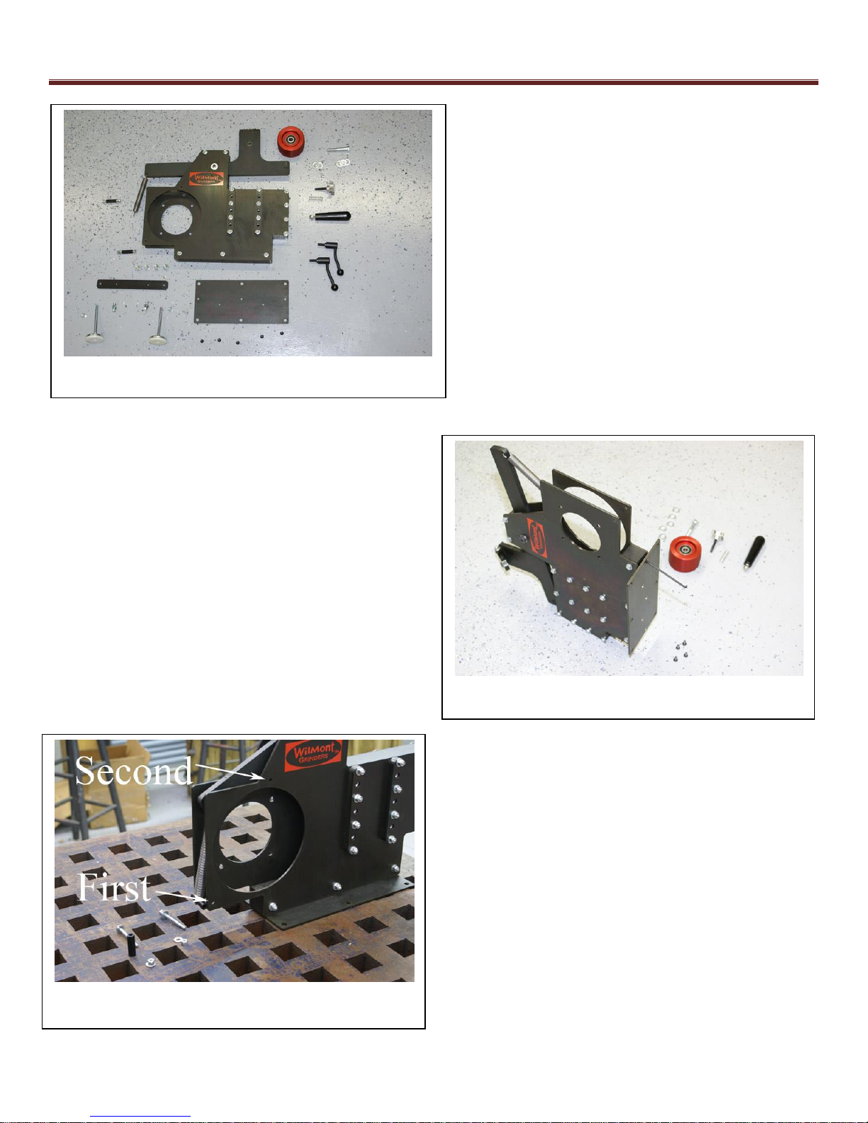
Photo 2 – Base Plate assembly
Photo 3 – Rod Spacer installation
Photo 1 – Wilmont Grinder Parts
5 Bolts as in Photo 2.
Wilmont Grinder Assembly Manual – TAG 101
In order to assemble your Wilmont Grinder you
will need a few basic hand tools:
o 7/16 wrench
o 7/16 Socket wrench
o 5/32 Allen wrench
o 7/32 Allen wrench
o 9/16 wrench
o 3/4 wrench
o 5/8 wrench
Step one: Bolt the bottom plate to the Grinder
body using the enclosed 5ea - ¼-20 x 5/8 long flat
headed Bolts. Using a 5/32 Allen wrench tighten all
Step two: Attach the two black round Rod Spacers
between the two Vertical Plates on your Grinder. Use
2ea – ¼ x 20 x 2 ½ inch Bolts with ¼ inch Washers &
Nyloc Nuts. It is important that you do this in the
correct order so that you are not fighting the spring
needlessly. The first one to connect is the one that
attaches through the end of the Spring, as seen in
Photo 3. If you have any issues with getting the
spacers between the two plates just loosen the closest
¼ x 20 Bolts to allow easier insertion.
Push down gently on the Pivoting Arm while inserting
the second Rod Spacer. When you have the Rod
Spacers in place, tighten all the ¼ inch Bolts that are
holding the Grinder body together. At this point, the
Grinder should be upright and sturdy. The Base Plate
has predrilled holes available for mounting to your
work surface. Alternately, you can mount the Grinder
to a board and then clamp the board to the work
surface.
1
Wilmont Grinder Assembly Manual – TAG 101
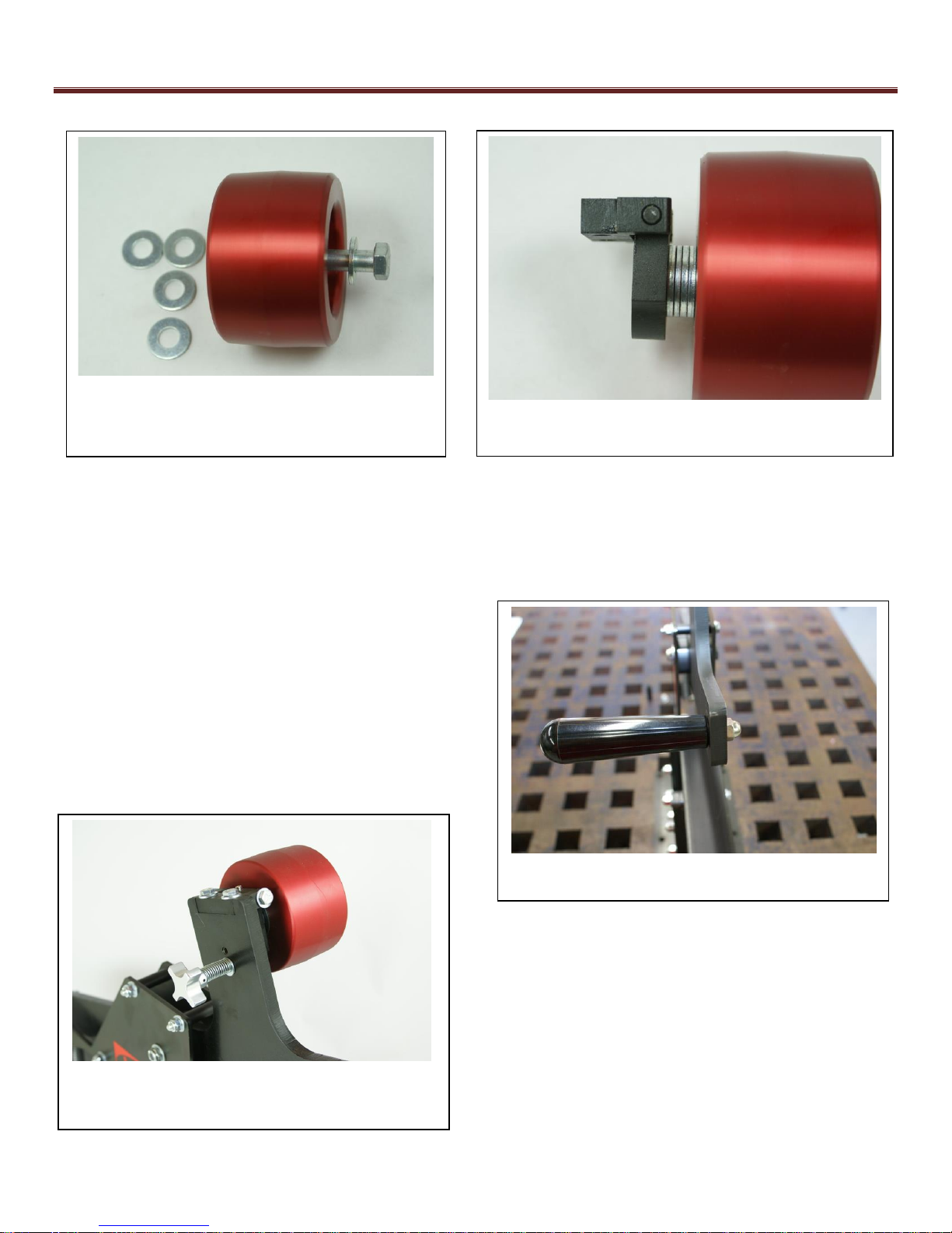
Photo 4 – Tracking Wheel
Photo 6 – Tapered Handle
Photo 7 – Tracking Control Knob
Step three: Install the red Tracking Wheel using the included ½-13 x 3” inch Hex Bolt. Placement of the 5ea -
½ Washers is crucial to proper tracking. 1 Washers go under the head of the Hex Bolt, as seen in Photo 4, and
4 between the Tracking Wheel and the Grinder, as seen in Photo 5. Tighten the Bolt with a ¾ wrench.
Step four: Thread the Tapered Handle onto the left
side of the Pivoting Arm and lock it down with the
Acorn Nut using a 5/8 wrench. Photo 6 shows the
proper installation of this Handle.
Step five: Thread the four star 5/8-16 Tracking Control
Knob (spring & washer) into the upper portion of the
Pivoting Arm, bottom hole, until you contact the hinged
Tracking Plate. Continue threading in until this Plate is
parallel with the sides of your Wilmont Grinder. See
Photo 7.
2
 Loading...