

Page 1
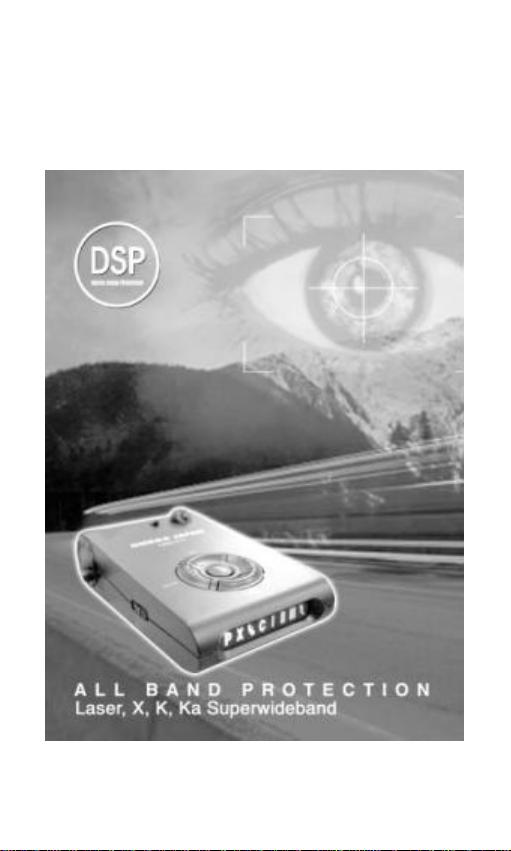
WILLTRONICS
D
etection system
WT1010
OWNER’S MANUAL
Page 2

FCC Information
Note: This equipment has been tested and found to comply with the limit for a
Class B digital device,pursuant to part 15 of the FCC Rules. These limits are
designed to provide reasonable protection against harmful interference in a
residential Installation. This equipment generates, uses, and can radiate radio
frequency energy and, if not installed and used in accordance with the
instructions. may cause harmful interference to radio communications.
However, there is no guarantee that interference will not occur in a particular
installation. If this equipment does cause harmful interference to radio or
television reception, which can be determined by turning the equi pment off and
on, the user is encourage to try to correct the interference by one or more of
the following measures:
- Reorient or relocate the receiving antenna.
- Increase the separation between the equipment and receiver.
- Connect the equipment into an outlet on a circuit different from that to
which the receiver is connected
- Consult the dealer or an experience radio/TV technician for help
Change or modification not expressly approved by the party responsible for
Compliance could void the user’s authority to operate the equipment
Page 3

CONTENTS
Ⅰ. MODEL FEATURES AND CONTROLS
Ⅱ. ACCESSORIES INCLUDED WITH RADAR DETECTOR
Owner’s Manual
Power Cord
Mounting kit
Hook & Loop Fasteners
Spare Fuse
Ⅲ. MOUNTING INSTALLATION
Windshield Mounting
Dash Board Mounting
Power connection
Ⅳ. OPERATION GUIDE
Power on & Self-Test
Feature Engaged Confirmation
Mute Mode
City/City1 Modes
Dim/Dark Modes
VG-2 Mode
Tutorial Mode
Memory Retention
Ⅴ. RADAR/ LASER/ VG- 2 ALERTS
Speed Radar Visual /Audio Alerts
Laser Visual /Audio Alerts
VG-2 Visual /Audio Alerts
Instant Visual/Audio Alerts
Safety Radar Visual/Audio Alerts
Ⅵ. TROUBLESHOOTING GUIDE
Factory setting
Ⅶ. SPEED MONITORING DEVICES
Radar speed gun
Laser speed gun
Radar Detector Detectors
Ⅷ. MAINTENANCE
Care and Maintenance
Fuse Replacement
Ⅸ. SPECIFICATIONS
Page 4

Ⅰ. MODEL FEATURES AND CONTROLS
X, K, Ka Super Wideband Detection
All Laser Detection
360° Laser Detectability
Safety Radar System (SA, SWS) Detection
VG2 (Radar Detector Detector) Detection
VG2 Undetectability
Instant On /Pulsed Radar Alert
Smart ICON Display (Bar LED:8 Cell)
Memory Retention
Bar-graph Signal Strength meter
Visual & Audible Alarms
External Laser Jack (Option)
Power On/Off with Volume Control
Mute Mode
Dim/Dark Modes
City/City1 Modes
VG2 Mode
Tutorial Mode
Page 5

1. Bracket Lock/Release Button
bracket.
2. Power Jack
3. Speaker
and the VG-2
4. Power/Volume Control
5. High Visibility ICON Display
signals strength, signal band identification and indicates engaged modes
of operation.
Connection for the power cord.
Provides distinct audio alarms for X, K, Ka band radar, laser
Easy lock/release of the mounting
Turns unit on/off and adjusts audio level.
Provides distinct visual confirmation of
Page 6
6. MUTE Button
audio alerts.
7. CITY Button
encountered in urban driving areas.
8. DARK Button
settings.
9. VG2 Button
10. T Button
11. Laser Lens (Rear)
detection of laser signals transmitted from behind
Pressing MUTE during a radar/laser encounter silences
Reduces the annoyance of false alerts typically
Reduces illumination of display to “dim” or “dark”
Pressing VG2 to engage or disengage VG-2.
Tutorial mode engage button
An integrated optical waveguide provides superior
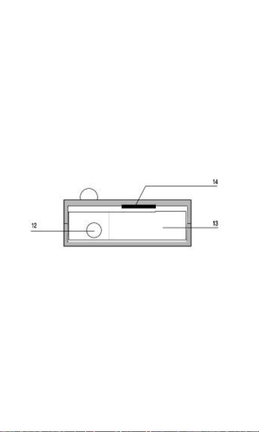
12. Laser Lens (Front)
sensitivity and field of view for leading edge laser detection.
13. Radar Antenna
signals.
14. Mounting Bracket Location
15. EXT
Port for external laser connection (Option Laser Module)
High gain optical lens array provides increased
Compact, high-efficiency antenna receives radar
Slot holds mounting bracket firmly.
Page 7
Ⅱ. ACCESSORIES INCLUDED WITH RADAR DETECTOR
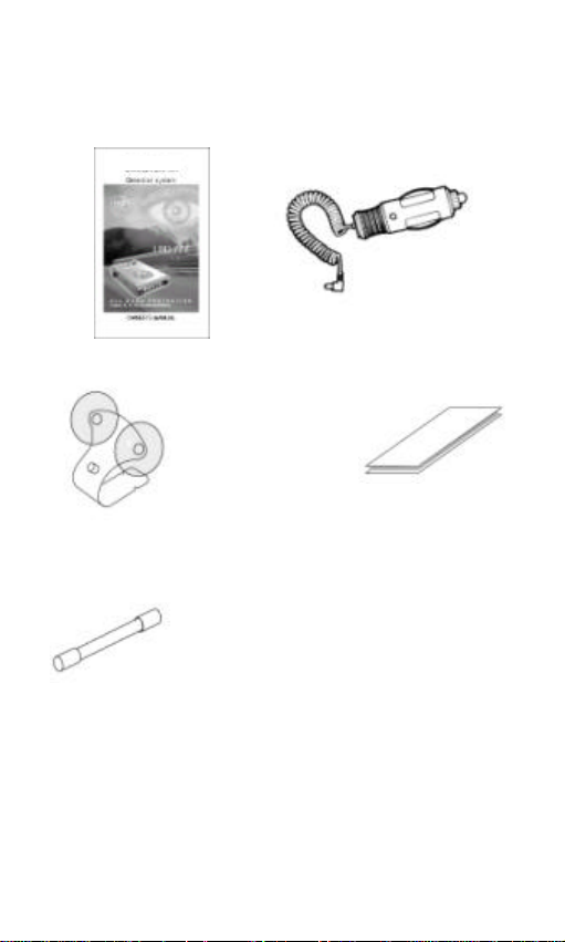
1. Owner’s Manual 2. Power Cord
3. Mounting kit 4. Hook & Loop Fasteners
5. Spare Fuse 2A 250V
Page 8
Ⅲ. MOUNTING INSTALLATION
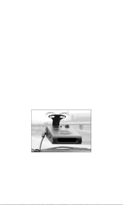
Mount the unit as low as possible near the center of the windshield.
Do not mount your unit behind wipers, ornaments, mirrored sunscreens,
etc. These obstructions have metal surfaces which can affect radar and
laser signals and reduce critical warning time. (Regular tinted glass does
not affect reception.)
Some newer windshields have an lnstaclear™ or Electriclear™ type
coating, which affect radar signals.
Avoid placing unit in direct contact with windshield.
To reduce the possibility of theft, conceal your unit when not in use.
Windshield Mounting
Install the mounting kit at the windshield as it follows.
IMPORTANT: Some newer cars have a plastic safety coating on the inside
of the windshield. The windshield bracket may leave permanent marks on
this type of surface. We recommend that you do not leave the suction
cup bracket on the window in direct sunlight. If the detector is removed,
this may cause blistering of the dash in some vehicles.
Slide the detector onto the bracket and get it locked with switch.
If necessary, the unit may be leveled by bending the windshield bracket.
Push the bracket release switch and remove the detector before bending.
Page 9
Dashboard Mounting
Make sure the mounting location you have chosen is relatively level and
is clean and dry. Clean with isopropyl alcohol if necessary to remove any
waxes or polishes.
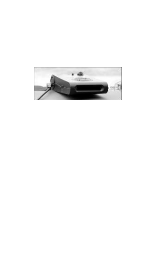
Separate the fastener strips. Peel the paper ba cking off each strip and
adhere one piece to the dash and the other piece to the bottom of the
unit, taking care
not to cover the serial number.
Be careful not to place the fastener strip over the unit’s serial number. If
the fastener strip is removed, the serial number may be pulled off the unit.
Units without serial numbers are not covered under warranty.
Power Connection
Plug the small end of the power cord into the unit’s power jack.
Plug the large end into the vehicle’s cigarette lighter.
Page 10
Ⅳ.OPERATION GUIDE
Power On And Self- Test
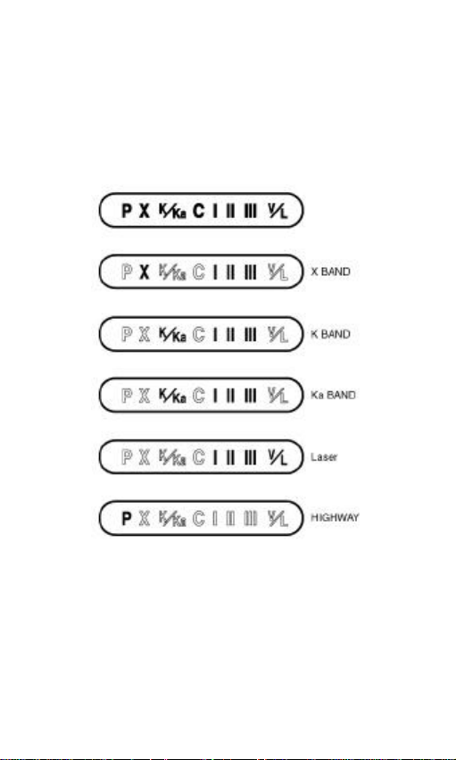
Each time your WT1010 detector is turned on, an automatic self-test
sequence confirms that the speaker and visual displays are functional and
displays the engaged features.
Turn Power/Volume control clockwise. Display reads:
Feature Engaged Confirmation
Each time a button is pressed one beep confirms feature “on”, two beeps
confirm feature “
off
”.
Page 11
Mute Mode
Press “MUTE” to cancel the audio when signal is detected.
City/ City 1 Modes
Two levels of City Mode are designed to reduce the annoyance of
automatic door openers for X band detecting sensitivity, intrusion alarms
and other devices which share frequencies with police radar.
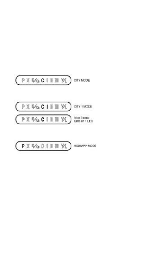
Press City to engage City, reduce X band sensitivity. Display reads:
Press City a second time engages City 1, which could be unable to
detect X band speed gun. Display reads:
Pressing City third time cancels City, City 1. Display reads:
In City Mode, weak speed/safety radar signals give an initial alarm of two
beeps, and then the unit remains quiet unless the signal becomes very
strong. When the signal strength increases, two additional beeps are
provided. In City 1 X-band is not detected.
cities may still be using X band radar.
CAUTION:
Some towns/small
Page 12
Dim/Dark Modes
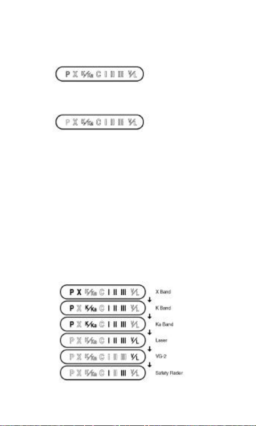
Dim/Dark Mode reduces the illumination of the display.
Press and hold “DARK” to reduce illumination to a Dim setting.
Press and hold the “DARK” button a second time for 2 seconds
engages Dark Mode.
Dim or dark can be engaged during an alert. In Dark Mode, the display
goes dark for as long as a signal is being detected and for 20 seconds
after, then the display returns to the dimmer setting.
Pressing and holding the “DARK” button a third time restores full
illumination to the display.
VG- 2 Mode
Press “VG-2” button to turn this feature on. Press “VG-2” button once
again to turn off.
Tutorial Mode
Provide simulated alerts for each type of signal.
Press “T” button for 2 sec to go tutorial mode.
Press “T” button again to exit.
Page 13
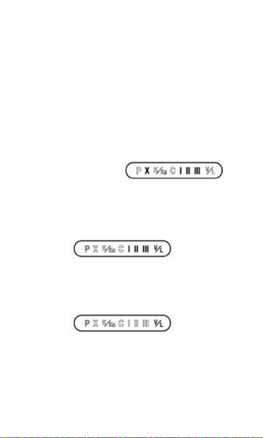
Memory Retention
Electronically remembers all your own settings for a certain period of time
after power-off.
Ⅴ. RADAR/ LASER/ VG- 2 ALERTS
Speed Radar Visual /Audio Alerts
When X, K or Ka is detected, the band ID and signal strength is displayed
with an audible alert.
. Signal strength ICON blinking Example: X band strong signal
I -> weak signal
I II -> middle signal
I II III -> strong signal
Laser Visual /Audio Alerts
When a laser signal is detected, the V/L ICON is on with signal strength,
the audio alert is continuous for a minimum of 3 seconds. Example:
VG- 2 Visual /Audio Alerts
When a VG-2 signal is detected, the detector “hides” its own radiated
signal and becomes undetectable by the VG-2. The ‘V/L’ ICON is only
blinking.
Every 30 seconds, the detector checks for a VG-2 signal. If a VG-2 signal
is still present, the unit continues to hide and repeats the VG-2 alert. If no
signal is detected, two beeps are provided, indicating an “all clear”
condition. During VG-2 Alert X, K, and Ka band signals cannot be
received
Page 14

Instant Visual/ Audio Alert
When a instant signal (strong signal) is detected, an urgent 3 second
audio warning is sounded and the display shows:
After 3 seconds standard alert pattern continues.
Safety radar Visual/ Audio Alert
The WT1010 detects the new Safety Warning system . This provides
advanced warning of various road hazards including accident sites,
highway construction, emergency vehicles and enables you to respond
more appropriately to potentially dangerous conditions. It provides a
distinct audio tone and illuminates the first strength bar and the last bar in
the display.
Page 15

Ⅵ. TROUBLESHOOTING GUIDE
PROBLEM:
Check fuse in the plug and replace if necessary with a 2 amp 3AG type.
Check fuse for lighter socket; replace if necessary.
Make sure lighter socket is clean.
PROBLEM:
Check for loose lighter socket; tighten and clean.
Check connections at both ends of power cord. Substitute another cord
to determine if cord is defective. Return defective cord to the factory.
PROBLEM:
accessories (brakes, power mirrors/windows, directionals, horn, etc.).
Vehicle’s electrical system, including battery and alternator, may have
electrical noise. Install a filter capacitor (470mfd. 25 volt or larger
capacitance value) on the back of the lighter socket.
No display or audio.
Unit alarms when vehicle hits bumps.
Unit alarms when using vehicle equipment or electrical
Factory setting
All user features can be reset to factory settings. Please follow below
steps for reset.
1. Unplug Power Cord from unit
2. Press and hold City and Mute.
3. Plug Power Cord into unit.
4. Wait for 2 beeps.
5. Release City and Mute button. Unit is now reset
- Factory reset Highway Mode ON.
Dim/Dark Mode to full illumination of display.
VG-2 Detection Mode OFF
Page 16

Ⅶ. SPEED MONITORING DEVICES
Radar speed gun
A radar gun operates by transmitting radio waves at certain frequencies
which reflect off objects and are then picked up by the radar gun’s
receiving section. When a radar beam reflects off a moving target, a
measurable frequency shift occurs. The radar unit converts this shift into
miles per hour to determine your vehicle’s speed.
Currently, the FCC (Federal Communications Commission) permits
operation of traffic radar guns at X Band(10.500 10.550 GHz), K Band
(24.050 24.250 GHz), and Ka Band (33.400 36.000 GHz).
Laser speed gun
It’s well documented that many radar guns cannot reliably provide the
speed of a targeted vehicle that is traveling in a group of vehicles. In
contrast, a laser gun can target a specific vehicle out of a line of traffic
and determine its speed.
The advantage of laser over radar in terms of target identification is the
result of the laser gun’s narrow beam. A radar transmission can cover
more than a four-lane highway at a distance of 1,000 feet, compared with
a laser transmission which covers about 6 feet at the same distance.
For best protection, keep these points in mind:
Because your vehicle’s license plate or headlights are the laser gun’s
primary targets, mounting your detector on the dashboard can improve
laser detection at short range.
Do not follow closely behind any vehicle you cannot see through. If you
can’t see past a vehicle ahead of you, chances are your detector won’t
either.
The receiving range of your laser dete ctor will not be the same as a
radar detector. Laser guns are most often used at short range.
Page 17

Radar Detector Detectors
The Interceptor VG-2, or simply VG-2, is a microwave receiver used by
police to detect signals radiated by the local oscillator of a radar detector.
Because its purpose is to identify persons driving with radar detectors,
the VG-2 is known as a “radar detector detector”.
Care And Maintenance
During the summer months, avoid prolonged exposure to direct sunlight
by removing your unit from the dash when your vehicle is parked for an
extended period of time.
Do not spray water, cleaners or polishes directly onto the unit. The spray
may penetrate through the openings and damage the unit. Also, do not
use any abrasive cleaners on the unit’s exterior.
Fuse Replacement
The lighter socket plug is equipped with a replaceable 2 amp 3AG fuse
located behind the silver tip. To replace the fuse, carefully unscrew the tip
of the plug. (
which may fly out when disassembling.) Insert the new fuse with the
spring and screw on the tip.
Ⅷ. MAINTENANCE
IMPORTANT:
Unscrew slowly. The tip contains a spring
With use, screw cap on plug may loosen. Retighten occasionally.
Page 18

Ⅸ. SPECIFICATIONS
General
Dimensions: 65mm(W) x 118mm(L) x 32mm(H)
Weight: 148 g
Power Requirement: 12- 15V DC
Temperature Range: Operating -20°C to +80°C
Storage -40°C to +100°C
Laser Detector
Receiver Type Pulse Laser Signal Receiver
Sensor Front End Convex Condenser Lens
Detector Type Pulse Width Discriminator
Receiver Bandwidth 30 MHz
Spectral Response 800- 1100 nm
Radar Detector
Receiver Type Double Conversion Superheterodyne
Detector Type Scanning Frequency Discriminator
Antenna Type Linear Polarization
Frequency of 10.525 GHz ± 50 MHz (X Band)
Operation
Specifications are subject to change without notice.
24.150 GHz ± 100 MHz (K Band)
34.700 GHz ± 1300 MHz (Ka Band)
Page 19

MEMO
 Loading...