

Page 1
Series
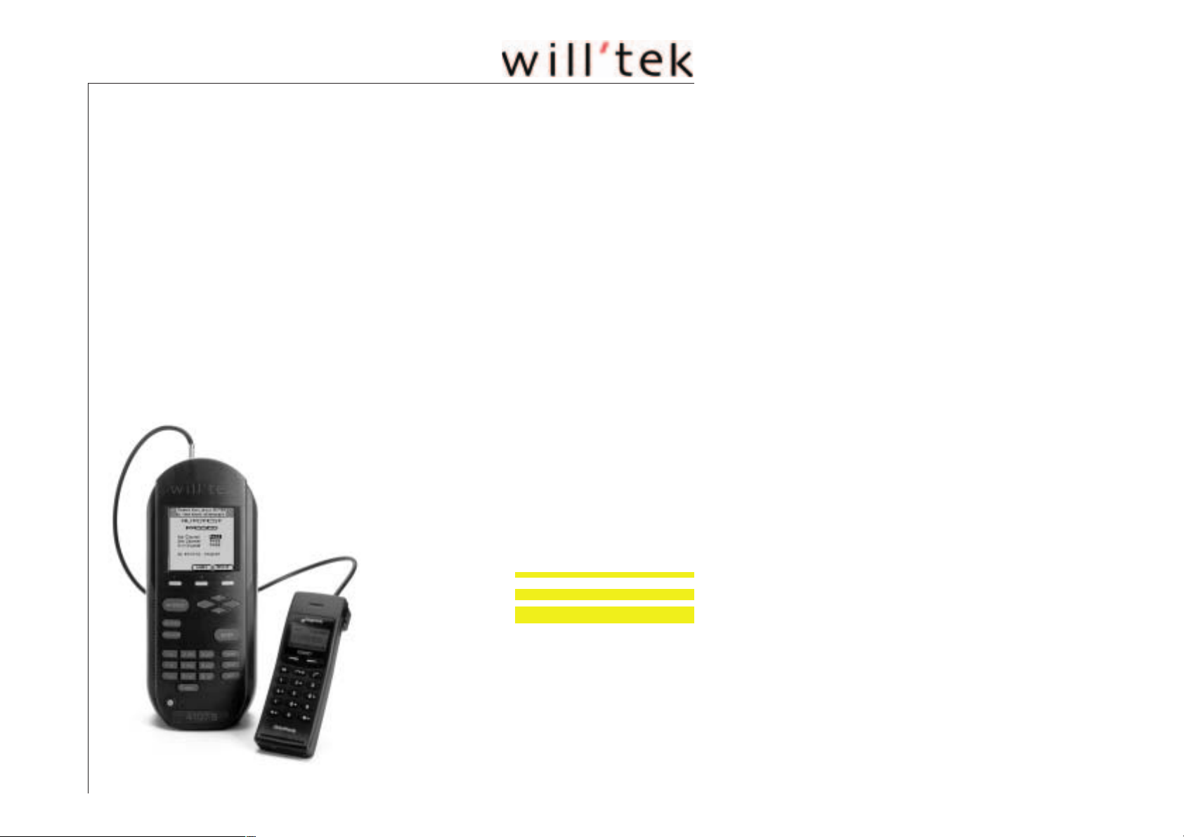
Willtek 4100
Mobile Phone Tester
GSM 900 n E-GSM n GSM 1800 (PCN) n GSM 1900 (PCS)
Dual band GSM 900+1800
Multiband GSM 900+1800+1900
n GSM 900+1900
User Guide
Manual Version: 0312-341-A
Page 2

Willtek 4100
Designations such as utility names, company names and trade names are not
specially indicated in this manual, as they are all widely known. Such names
may, however, be the property of companies or other such bodies.
This manual is subject to change at any time without notice. Errors and omis
sions excepted.
© 1997 - 2003 Willtek Communications GmbH. All rights reserved. No part of
this manual may be reproduced or transmitted in any form or by any means
(printing, photocopying or any other method) without the express written per
mission of Willtek.
Manual layout and text: Redaktion Interpreta, Munich, Germany
-
-
1-2
Page 3

Willtek 4100
Contents
Chapter 1: GETTING STARTED
Preface ............................1-10
Operating modes ......................1-10
Important instructions ...................1-12
Proper operation ......................1-12
After unpacking .......................1-13
Key functions ........................1-14
Initial startup.........................1-16
Attaching the power supply unit ..............1-16
Start menu .........................1-16
Chapter 2: SETUP
Basic settings.........................2-2
Contrast ...........................2-2
Language ..........................2-3
Printer ............................2-4
Date and time ........................2-5
Header ............................2-6
PC interface .........................2-7
Choose the protocol .....................2-8
Sound ............................2-9
Self check..........................2-10
Accessing the menus ....................2-10
System information .....................2-10
Printer test .........................2-11
Keyboard test ........................2-12
Display test .........................2-12
Internal test .........................2-13
Preparing the tests .....................2-14
Installing the test SIM....................2-14
Background information: SIM................2-15
Attaching the test unit....................2-16
Connection via antenna ..................2-16
Points in favor .......................2-16
Points to note .......................2-16
Connection .........................2-17
Connection via the Universal Antenna Coupler ......2-18
Points to note ........................2-18
Connection .........................2-18
Cable-based connection ..................2-19
Points to note .......................2-19
Connection .........................2-19
1-3
Page 4

Willtek 4100
Chapter 3: AUTOTEST
Overview ............................3-2
The influence of the user...................3-2
Running an AUTOTEST ...................3-3
A Standard AUTOTEST is carried out as follows ......3-4
Be prepared for input breaks.................3-4
When an AUTOTEST aborts.................3-4
The input breaks of a Standard AUTOTEST.........3-5
Lifting a tester block .....................3-6
Results of the AUTOTEST .................3-7
AUTOTEST PASSED ....................3-7
What to do if you are in doubt ................3-7
Softkey functions.......................3-7
AUTOTEST FAILED .....................3-8
Fault analysis ........................3-8
Sample AUTOTEST log (excerpt) .............3-10
Evaluating stored AUTOTESTs..............3-11
Selecting a stored log....................3-11
Softkey functions ......................3-12
Available capacity for storing AUTOTESTs ........3-12
Downloading logs to a PC .................3-12
Entering test parameters .................3-13
1. Assigning a name to a record ..............3-14
2. Selecting the radio system ................3-15
3. Selecting the connection type ..............3-15
4. Selecting the AUTOTEST ................3-16
At least one AUTOTEST ..................3-16
Background: AUTOTEST..................3-17
Standard AUTOTESTs ...................3-17
User-defined AUTOTESTs .................3-18
5. Channel selection ....................3-19
6. Entering compensation values ..............3-20
Background: signal attenuation...............3-20
Effect of the connection type ................3-21
Determining compensation values .............3-22
Cable-based connection ..................3-22
Universal Antenna Coupler .................3-22
Copying records ......................3-24
1-4
Chapter 4: FAULT FIND
Overview ............................4-2
The mode for experts ....................4-2
Accessing FAULT FIND mode ................4-3
Access with the Willtek 4107S ................4-3
Page 5

Willtek 4100
FAULT FIND test preparation ...............4-4
Selecting the radio system .................4-4
Special considerations for dual-band systems........4-5
Special features of multiband systems............4-6
Testing multiband mobile phones ..............4-6
Selecting channels/RF power ................4-7
Entering channel numbers ..................4-7
Setting the RF power ....................4-8
Compensating for signal attenuation.............4-9
Compensation values ....................4-9
Installing the test SIM....................4-10
Connecting the mobile phone ...............4-10
This is what is tested ....................4-11
Test 1.0: Network identification and registration .....4-12
Problems with registration .................4-13
Problem solving.......................4-13
Test 2.0: MS CALL connection setup ..........4-14
Test 3.0: BS CALL connection setup ..........4-15
Test 4.0: Messages and measurements ........4-16
Test 4.1: Changing the voice channel ...........4-22
Test 4.2: Reducing the RF power (from the tester) ....4-23
Test 4.3: Changing power levels ..............4-24
Test 4.4: Clear down on the mobile phone ........4-25
Test 4.5: Clear down on the tester .............4-26
Test 5.0: Measuring the bit and frame error rate ......4-27
Test 6.0: Checking mobile phone identification .....4-29
Test 7.0: Speech testing ..................4-32
Test 8.0: Cell Broadcast test ...............4-34
Chapter 5: Additional Features
Introduction ..........................5-2
Additional features ......................5-2
Asynchronous Mode ....................5-3
Preparation and starting ...................5-4
Changing bands on multiband devices ..........5-5
Emission of a carrier signal .................5-5
Test results in Asynchronous Mode .............5-6
Remote Control........................5-8
Preparation..........................5-8
Starting remote mode ....................5-8
Special characters in SCPI .................5-9
SCPI syntax .........................5-9
Abbreviations ........................5-9
Command indicators .....................5-9
1-5
Page 6

Willtek 4100
Composite commands ...................5-10
Parameters .........................5-10
Text .............................5-10
Numeric...........................5-10
Boolean ...........................5-11
Queries ...........................5-11
Result formats .......................5-11
Query ............................5-11
Settings and queries ....................5-12
Multiple measurement ...................5-12
Compatibility ........................5-12
SCPI command sets ....................5-13
Sample program ......................5-52
Quick reference .......................5-54
Chapter 6: APPENDIX
Technical data ........................6-2
Interfaces ...........................6-3
HD sub-26 socket ......................6-3
Mini-DIN socket .......................6-4
TNC socket .........................6-4
Printing.............................6-5
This is what you can print ..................6-5
Printer requirements .....................6-5
Connecting a printer .....................6-5
Testing the printer ......................6-6
Troubleshooting .......................6-6
Data transfer between the tester and the PC ......6-8
Where can I get the software? ................6-8
Installing the software ....................6-8
Preparation..........................6-9
The Program window ....................6-10
No data transfer? ......................6-11
Error messages.......................6-11
Performing a firmware update ...............6-12
Abortion during an update .................6-13
Copying MS TYPE records .................6-14
Exporting an MS TYPE list to PC..............6-14
Importing an MS TYPE list from the PC ..........6-15
Exporting test logs .....................6-16
Export options .......................6-16
Examples of exported test logs ...............6-20
Importing AUTOTESTs ...................6-21
Command line parameters .................6-23
General notes........................6-24
1-6
Page 7

Willtek 4100
Upgrading your model ..................6-25
On-site upgrade or service centre?.............6-25
Updating the firmware ...................6-26
This is how to get your update package ..........6-26
To update you will need these ...............6-27
Contents of the update package ..............6-27
Performing the update ...................6-27
The code used in log listings ...............6-28
Troubleshooting ......................6-33
Willtek 4100 Timeline....................6-35
Accessories and options .................6-38
Standard accessories ...................6-38
Extra accessories .....................6-38
Options ...........................6-39
RF adapters ........................6-40
Overview GSM threshold values .............6-41
1-7
Page 8

Willtek 4100
1-8
Page 9

Willtek 4100
!
GETTING
STARTED
1-9
Page 10
Preface Willtek 4100
Preface
Thank you for choosing a model in the Willtek 4100
series. The equipment will give you valuable assistance
in functional testing and troubleshooting on GSM
mobile phones.
Model Frequency band Network
GSM 900/1800/1900 Single band
Willtek 4107
Willtek 4107L
Willtek 4107S
0,9/1,8/1,9 GHz
Willtek 4107S The Willtek 4107S offers a number of additional
features compared with the Willtek 4107 (see chapter 5
for details). The S version can be identified by the type
label and the model name in the start menu.
Willtek 4107L Special inexpensive model only available bundled with
other products (eg 4192 GSM Phone Checker
software). The same range of functions as the
Willtek 4107, except that FAULT FIND mode is not
available. This model can, however, be remotely
controlled (see chapter 5). Please contact our Sales
department for details.
E-GSM Single band
GSM 900+1800 Dual band
GSM 900+1900 Dual band
GSM 900+1800+1900 Multiband
1-10
n
Operating modes
[AUTOTEST] Fast and accurate full testing of a mobile phone with an
overall assessment of PASSED (mobile phone OK) or
FAILED (mobile phone defective). Largely automatic
testing requiring no system expertise on the part of the
user.
[FAULT_FIND] Operating mode for error location on defective mobile
phones (not available for Willtek 4107L). Selective
performance of individual tests. Displays
measurements for assessment by experienced users.
Page 11

Willtek 4100 Preface
This User Guide is applicable to all models in the
Willtek 4100 series. The generic name 4100 is used
&
Do you speak English? The testers have a display which can show text either
whenever the Guide refers to features which are not
specific to a particular model.
in English or in some other language. This Guide
assumes that you have selected English, in which case
the illustrations and instructions will match up with what
you see on your tester's display.
If some other language is selected, the Guide and the
display no longer match up. In that case either translate
what the Guide says into the other language or switch
the language to English for a short period (see also
page 2-3).
1-11
Page 12

Important instructions Willtek 4100
Important instructions
Proper operation
AC power Permissible line voltage: 100 V through 240 V
(AC voltage; 47 Hz through 63 Hz). The power supply
unit automatically adapts to the line voltage.
Use for intended purpose only Use your Willtek 4100 only for its intended purpose for
function testing and repairs on the radio telephones of
a GSM mobile radio system.
Ambient conditions Store and operate your Willtek 4100 only in a dry and
dust-free environment.
Operate your Willtek 4100 only in the permissible
temperature range of 15 °C through 35 °C. Observe the
permissible storage temperatures (see Appendix:
Technical data).
Breakable display Do not press down on the display.
Air circulation Keep the air vents free of obstruction.
Electromagnetic compatibility The device emits RF radiation. For this reason, do not
operate it in EMC-sensitive environments if this might
result in danger (e.g. when traveling in automobiles or
during flights). The EMC and Safety directives to which
the device conforms are listed in the Declaration of EU
Conformity (see Chapter 6).
Do not open Do not make technical modifications to the device or its
accessories. Do not open the device. There are no
parts inside it which require maintenance or disposal.
Do not open the device, otherwise you will lose your
claim to warranty.
Original accessories only Use original accessories only.
No solvents Do not use agents which contain solvents to clean the
equipment casing.
1-12
Page 13
Willtek 4100 Important instructions
Handling Avoid the following during operation and storage:
- strong direct sunlight
- vibrations, heavy impacts
- ingress of liquids or small objects into the device
- bending of the RF adapter cable
- contamination of the electrical contacts
After unpacking
Do not throw the packaging of your Willtek 4100 away.
l
It will make shipment easier if you want to have your
model upgraded later (see also page 6-25).
Check that the delivery is complete:
l
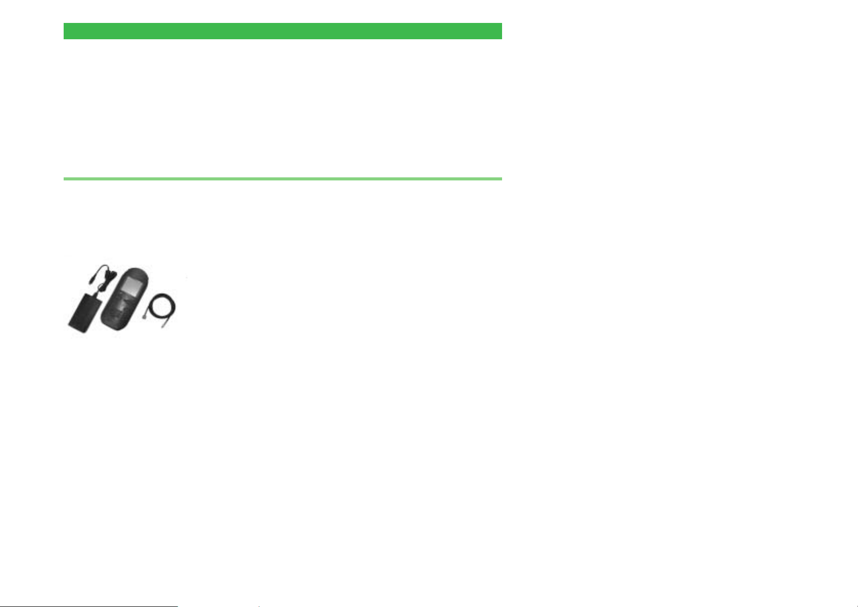
Standard items supplied
M 101 2XX 1x
M 860 188 1 x Test SIM, plug-in format
M 295 012 1 x Getting Started manual
M 897 055 1 x CD with User Guide in PDF format
M 860 105 1 x Power supply unit with power cord and connecting
M 860 409 1 x RF adapter cable
Willtek 4100
cable
Options/extra accessories For a list of useful options and extra accessories refer
to Chapter 6.
l
Check that the unit is undamaged:
Do not attempt to operate a WIlltek 4100 if there
is obvious damage to the device, the power
w
supply unit or the accessories. Retain the
packaging and contact the office who supplied
the equipment.
1-13
Page 14

Important instructions Willtek 4100
Key functions
The cursor keys have two functions:
selecting menu items
l
when entering numbers/letters: moving to the required
l
location
{F1} {F2} {F3} Softkeys: The current function of a key is assigned by
the currently visible menu. If no such assignment has
been made, the softkey is irrelevant.
1-14
Page 15
Willtek 4100 Important instructions
[AUTOTEST] Switches to AUTOTEST mode (quick test of mobile
phones)
[FAULT_FIND] Switches to FAULT FIND mode (troubleshooting – not
available for Willtek 4107L)
[TEST_RESULTS] Displays a list of AUTOTEST logs you have stored (e.g.
if you want to print a certain log)
[ENTER] The [ENTER] key has three functions:
confirming input
l
opening a submenu
l
launching a program
l
{1abc]...[9__yz} The number-and-letter keys have the following
functions:
entering the numbers 1 through 9 (e.g. phone numbers)
l
l entering the letters A through Z (e.g. comments)
[0_space_] Enters the digit 0 or a space
[ESCAPE] The [ESCAPE] key has two functions:
l
returning to the next menu up
l
aborting the current test
[SETUP] Calls the setup menu (for basic parameter settings
such as language and contrast)
[HELP] Calls up brief explanations of the currently visible menu
On/off button
1-15
Page 16
Initial startup Willtek 4100
Initial startup
All you need to do to start up your Willtek 4100 the first
time round is connect it to the power via the
accompanying power supply unit.
Attaching the power supply unit
n
! Plug the 8-pin connector coming from the power supply
unit into the matching socket on your Willtek 4100.
When plugging the connector into the socket, be
sure to observe the mechanical coding on the
w
socket and the connector. If these do not match,
the connector will not fit into the socket. Do not
use force! Use only the original power supply unit.
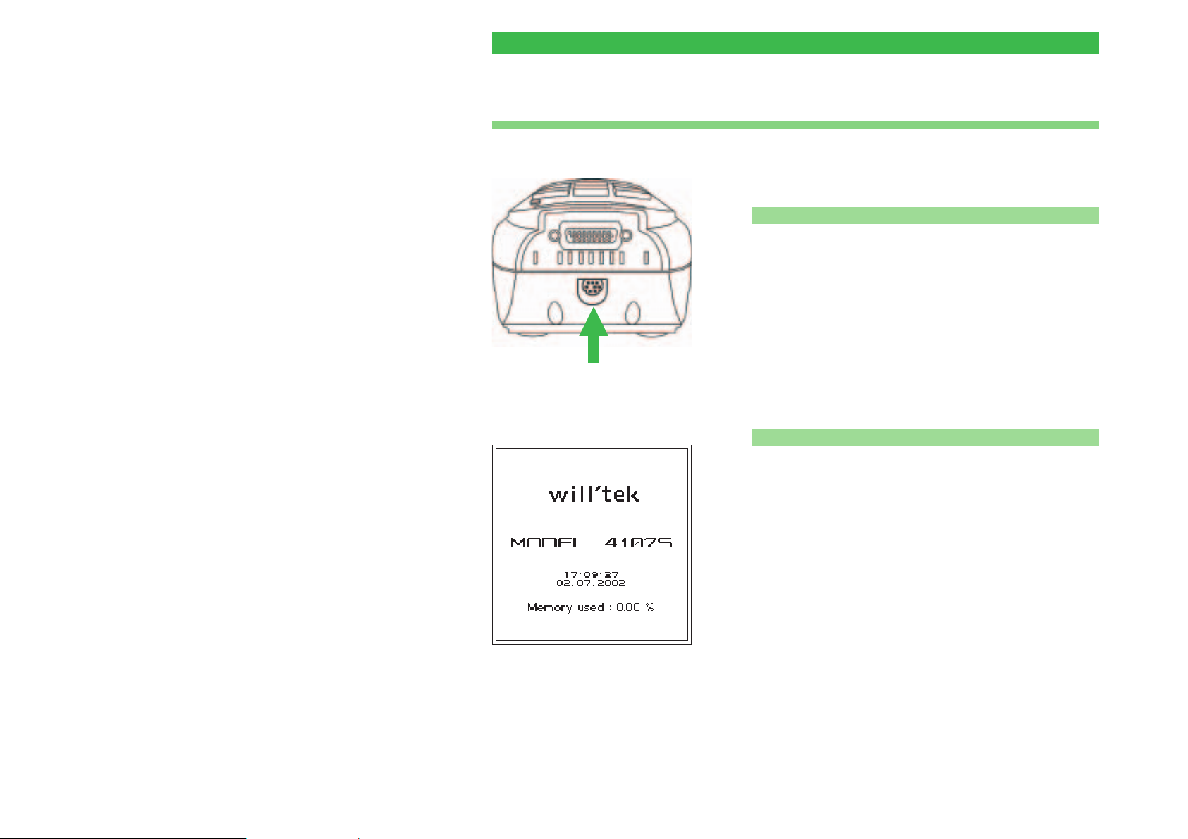
Attach power supply unit here
Start menu of the Willtek 4107S.
" Connect the power supply unit to the wall power outlet.
§ Press the on/off button to switch your Willtek 4100 on.
n Start menu
Immediately after being switched on, the Willtek 4100
briefly displays an initialization menu (in this period
among other things the operability of the device is
checked).
The tester is fitted with a maintenance-free fan in order
to keep the semiconductor components cool. The level
of noise produced by the fan is normal.
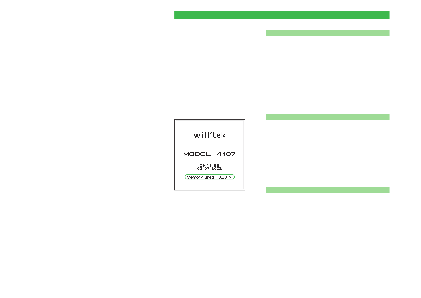
Once you see the start menu (picture on left), the
device is ready for use.
The first time you start up the device, you should at this
point press the [SETUP] key to adapt the basic
configuration of your Willtek 4100 to match your
specific requirements (see Chapter 2).
1-16
Page 17

Willtek 4100
"
SETUP
2-1
Page 18
Basic settings Willtek 4100
Basic settings
Contrast
ï
ï
[SETUP]
As a rule, the basic settings need only be configured
once during initial startup. A powerful capacitor ensures
that the settings and the stored test result are
preserved when your Willtek 4100 is off.
The tester should be on for about 4 hours at
+
least every 14 days (for capacitor charging) to
ensure that no data is lost.
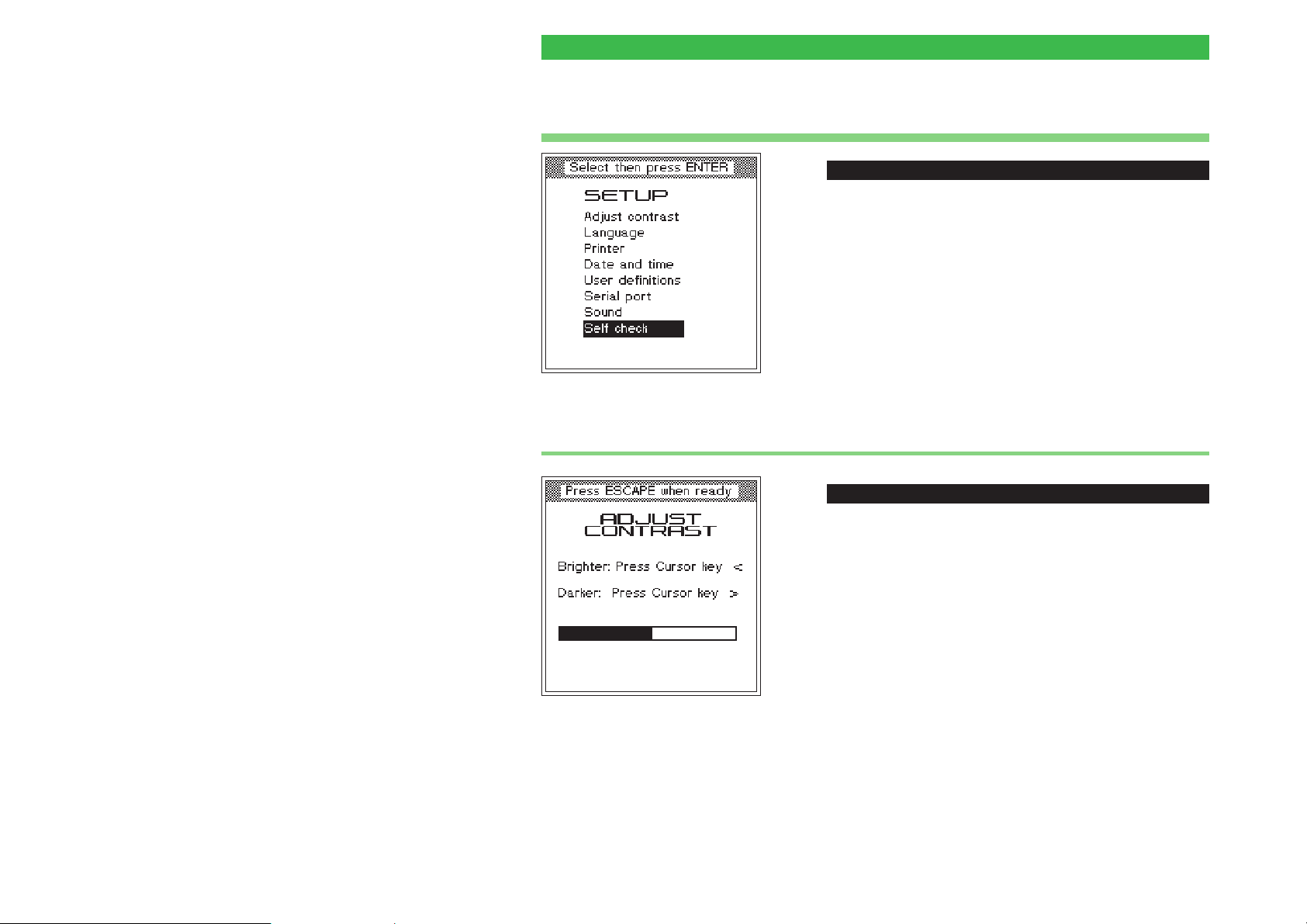
[SETUP] + Adjust contrast + [ENTER]
To adjust the readability of the display to the ambient
conditions.
! Using the cursor keys, alter the contrast to produce
optimum readability from the normal viewing angle.
" Return with [ESCAPE].
2-2
Page 19
Willtek 4100 Basic settings
Language
ï
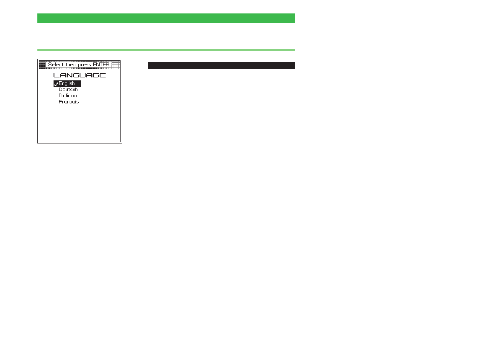
[SETUP] + Language + [ENTER]
To select the language in which the display shows text.
! Select one of the languages offered using the cursor
keys.
" Confirm your selection with [ENTER].
§ Return with [ESCAPE].
The languages currently offered are English,
+
German, Italian and French. Other languages
are being prepared, and these will be made
available in the form of a firmware update (see
page 6-26).
2-3
Page 20
Basic settings Willtek 4100
Printer
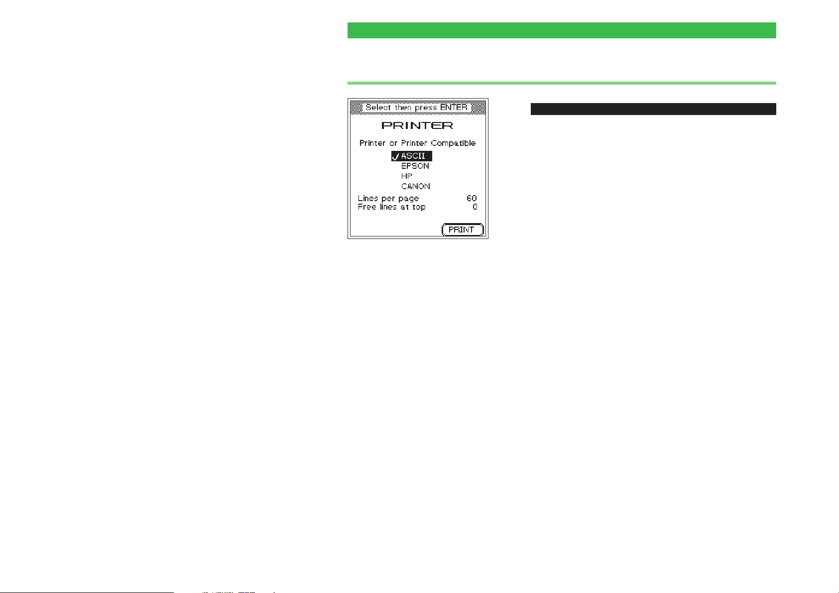
Press the {PRINT} key to print a test
page using the current settings
(see also page 6-6).
Example of page length
Lines per page = 59
Free lines at top = 9
Nine lines will remain blank at the top
of the page. This means that a total of
50 lines will be available on each
page for the test results (59 - 9).
Whether these will fill the entire page
or not depends to a large extent on
the font settings on the printer, since
the Willtek 4100 just outputs the
characters.
The way in which the characters
appear on the paper (font, size, line
feeds) is determined by the printer
on the basis of the settings made
on the printer. This means that you
can only change the appearance of
the test results by changing the
printer's settings.
ï
[SETUP] + Printer + [ENTER]
To select a printer for outputting test results.
! Using the cursor keys, select the manufacturer of your
printer (EPSON or HP). Printers from other
manufacturers can also be used, provided that they
have an HP or Epson emulation available. Select ASCII
if your printer is neither Epson nor HP-compatible.
All printers which do not require the use of a
+
driver under DOS can be used directly. More
recent Windows printers are therefore generally
unsuitable. Printers of this type can, however, be
used to print exported test logs from the PC (see
page 6-16).
" Confirm your selection with [ENTER].
Setting the page length
The value you specify for Lines per page determines
the number of printed lines per page (including blank
lines at the top of the page) when you print test results.
Once this number of lines is reached on the printout,
the tester issues a form feed. The specification you
make for Free lines at top sets the number of blank
lines at the top of the page (if, for instance you want to
avoid overwriting a letter header).
! Move to the entry fields with the cursor keys, enter the
required value and confirm every entry with [ENTER].
" Return with [ESCAPE].
For information on connecting a printer to your
+
Willtek 4100 and on printing test results, refer to
page 6-5.
2-4
Page 21
Willtek 4100 Basic settings
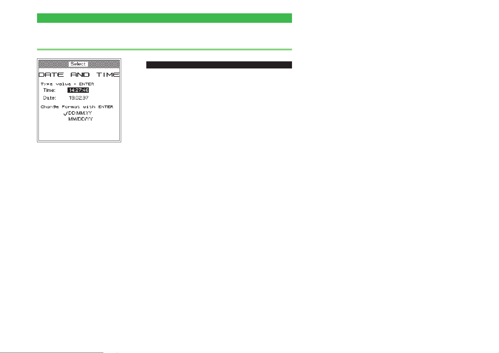
Date and time
Changes to the date format are
reflected by swapping of the first
two values in the "Date" line.
Each time you confirm a setting
you can either go on to configure
another setting or press [ESCAPE]
to quit the menu.
ï
[SETUP] + Date and time + [ENTER]
To set the date and time (shown on the start menu and
printed on test results).
Date format
! Using the cursor keys, select the date format you
require (shown at the bottom of the display):
DD/MM/YY = day/month/year
MM/DD/YY = month/day/year
" Confirm your selection with [ENTER].
Time
! Using the cursor keys, select the "Time" line.
" Enter the current time in 24-hour format (comparable to
entering a 6-digit number on a pocket calculator).
Example: 10:32
Input: 103200
§ Confirm your input with [ENTER].
Date
! Using the cursor keys, select the "Date" line.
" Enter the current date in the selected date format
(comparable to entering a 6-digit number on a pocket
calculator).
Example: June 14, 1997
Input: 140697 or 061497
§ Confirm your input with [ENTER].
Return with [ESCAPE].
2-5
Page 22
Basic settings Willtek 4100
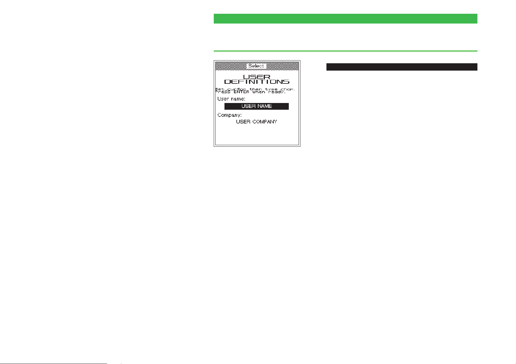
Header
Example {1_abc]
Repeated pressing of the {1_abc]
key causes the following characters to be entered at the cursor position:
1st press = A
2nd press = B
3rd press = C
4th press = 1
5th press = A
6th press = B
etc.
ï
[SETUP] + User definitions + [ENTER]
To enter the text that you want to appear in the header
on printed tested reports (e.g. user/company).
! Using the cursor keys, select the required input line.
" Enter text letter by letter (digits are also acceptable)
using the keys on the numeric keypad. Repeated
pressing of a number key first displays all the letters
assigned to that key and then the digit:
Automatic text entry: Avoid pauses between
–
selecting characters. If you pause for more than
approx. 1 second between selecting two characters,
the character currently visible is used and the cursor
moves to the next entry position.
– Corrections: Use the left or right cursor key to
position onto the incorrect character and then
overwrite the character.
–
Use the [0_space] key to enter spaces.
§ Confirm your input with [ENTER].
$ Using the cursor keys, move to the second input line
and enter text – or return with [ESCAPE].
2-6
Page 23
Willtek 4100 Basic settings
PC interface
Why data communication?
Setting up a data communication link
between a PC and your Willtek 4100 is
not difficult, but it can be really useful!
For example, you are able to
download the latest firmware versions
from the Internet, and feed them into
your Willtek 4100, or selectively
upload user-specific AUTOTESTs and
limit values that are geared to specific
models of mobile phone. Willtek also
has the right software for your data
communication requirements (some of
which are optionally available).
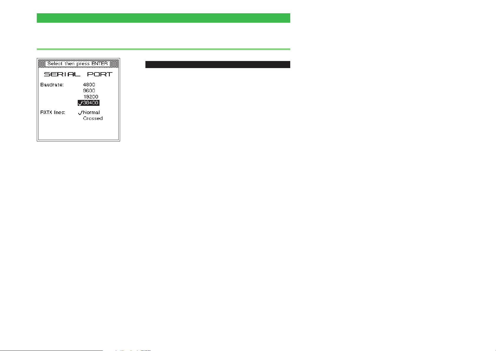
ï
[SETUP] + Serial port + [ENTER]
To set the baud rate (bit/s) for serial data
communication between PC and Willtek 4100, and to
select the type of communication line.
! Using the cursor keys, select the required baud rate.
The higher the baud rate, the shorter the transmission
time. On older PCs it may be necessary to select one
of the lower rates to ensure error-free data
transmission. Further data communication parameters
are permanently set (in the background) to:
8 data bits – no parity – 1 stop bit
" Confirm your selection with [ENTER].
§ If you are using one of the original cables for serial data
communications (extra accessories: Serial adapter
cable or Universal adapter cable), please select the
entry Normal under RXTX lines using the cursor keys.
If you are using other cables (e.g. extension cables),
lines RXD and TXD can be crossed (Pin 2 and Pin 3,
see also page 6-3). In this case, please select Crossed.
$ Confirm your selection with [ENTER].
% Return with [ESCAPE].
The values set for the serial interface (COM port)
+
on the PC must be the same as those set on the
Willtek 4100. If the PC also asks you about the
(transmission) protocol, the (transmission)
protocol, select "NONE". For instructions on
setting the baud rate of the serial interfaces
(RS-232-C) and the other parameters on your
PC, refer to the manual for your operating
system (DOS, Windows 3.xx, Windows 95).
2-7
Page 24
Basic settings Willtek 4100
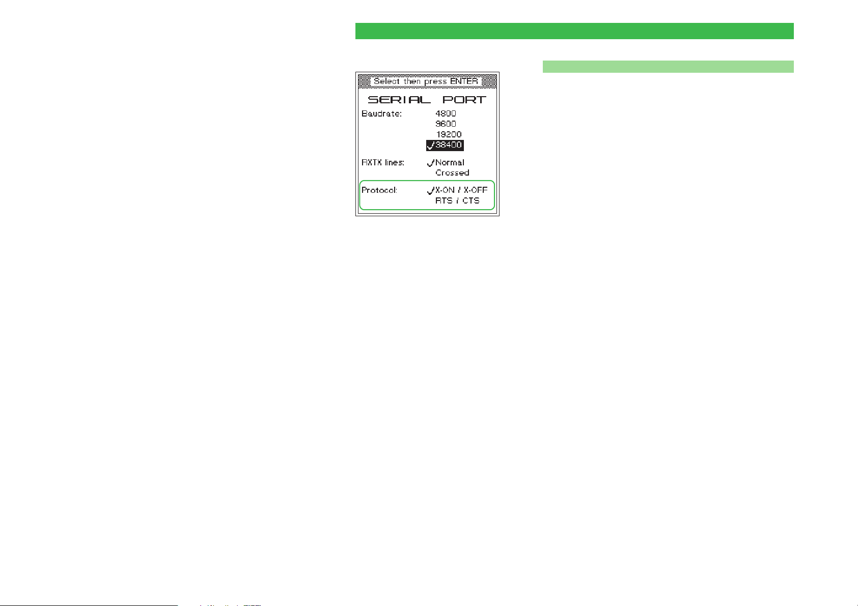
Choose the protocol
n
When a tester is under remote control, the transfer
protocol ensures error free transfer of data between the
PC and the tester (handshaking). You can choose
between one software protocol and one hardware
protocol (Willtek 4107S only).
X-ON / X-OFF Choose this software protocol if the
RTS and CTS lines are missing in the
cable connecting the PC and the tester
(see also page 6-3).
RTS / CTS If you are using a fully-wired cable (ori
ginal Willtek accessories), you should
choose this fast hardware protocol in
preference to the slower software protocol.
On the PC, the same protocol must be set for the
+
serial interface (COM port) used as for the
Willtek 4107S.
The protocol you set only takes effect when the tester
is under remote control and does not interfere with data
transfer using other protocols (e.g. when loading a
firmware update).
-
2-8
Page 25
Willtek 4100 Basic settings
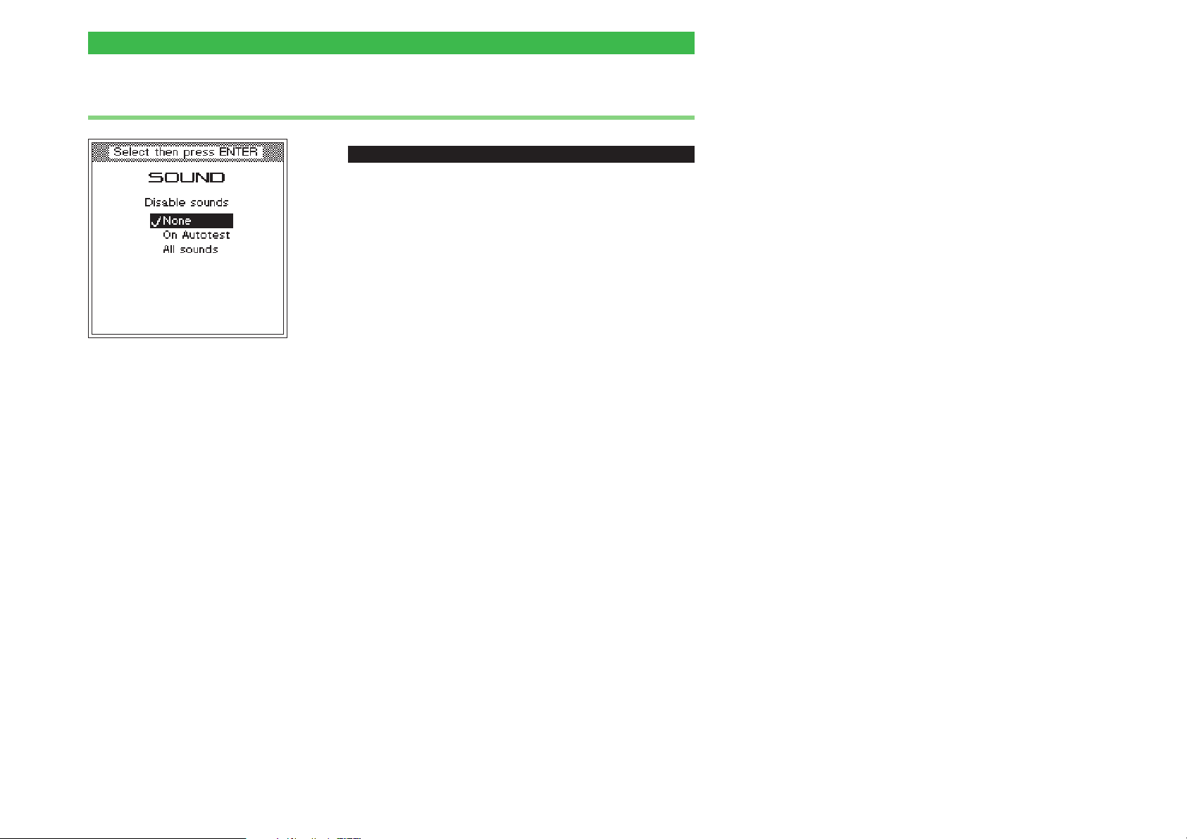
Sound
ï
[SETUP] + Sound + [ENTER]
Enable or disable the sounds used by the Willtek 4100
to signal special operating status (e.g. when a key is
pressed, when an error occurs or when the device is
ready).
! Using the cursor keys, select the required setting.
None Sounds are always active.
On Autotest Sounds are deactivated during an
AUTOTEST.
All Sounds Sounds are always deactivated.
" Confirm your selection with [ENTER]
2-9
Page 26

Basic settings Willtek 4100
Self check
ï
[SETUP] + Self check + [ENTER]
The Willtek 4100 checks its hardware modules and
indicates whether they are working correctly. It also
displays information on the version status of individual
modules.
Accessing the menus
Once you see the SELF CHECK menu on the display,
access to the submenus always follows the same
pattern:
! Use the cursor keys to select the menu you require.
" Confirm your selection with [ENTER]. The display then
shows the menu you have selected. On some menus
you can then use softkeys to start self checks.
§ Return with [ESCAPE].
System information
ï
[SETUP] + Self check + [ENTER] + System info + [ENTER]
The SYSTEM INFORMATION menu shows the
following information:
–
the serial number of the tester
–
the model number
–
the firmware version number
–
the date and time of the creation of the firmware at
Willtek
–
details relating to the hardware level of the device
2-10
Please have the information on this menu
+
ready when contacting Willtek for product
support (Press {PRINT} to start printing the
menu).
Page 27
Willtek 4100 Basic settings
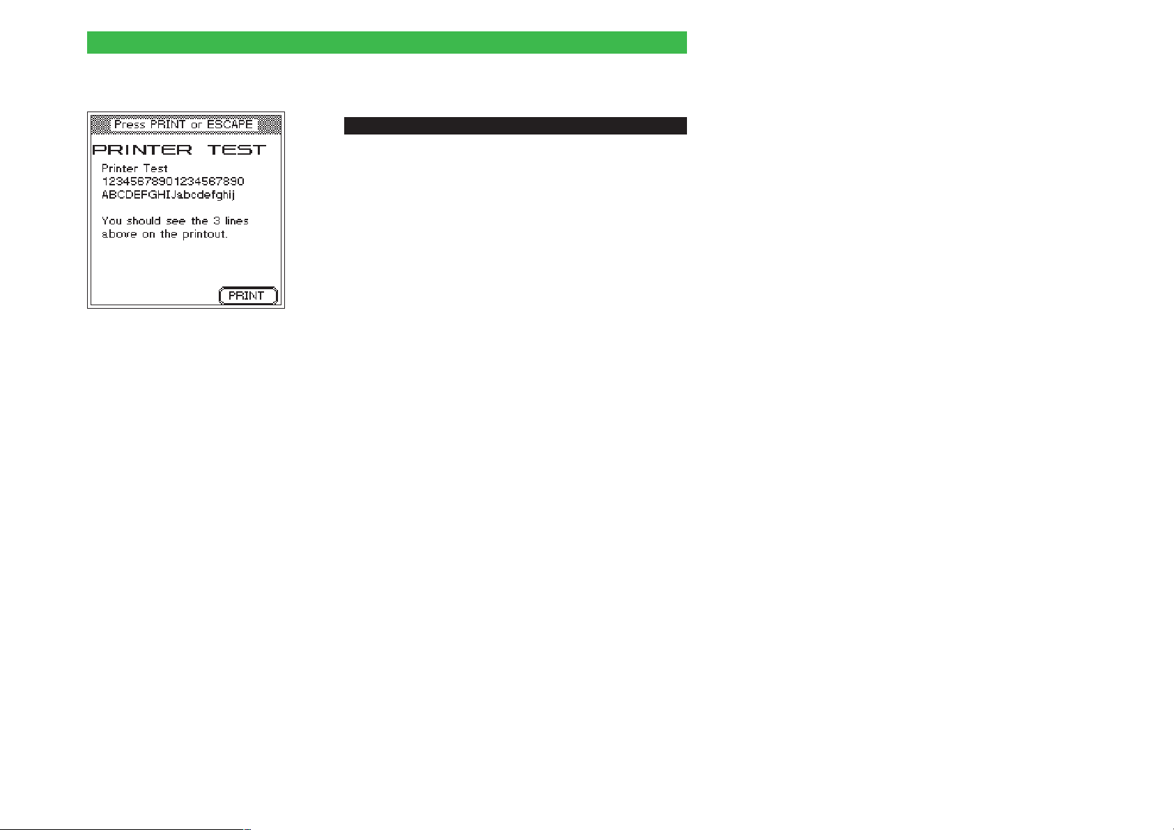
Printer test
ï
[SETUP] + Self check + [ENTER] + Printer test + [ENTER]
To test the printer.
! Attach your Willtek 4100 (26-pin socket) to the printer,
typically using the Universal adapter cable (extra
accessory).
" Press {PRINT} to start the printer test.
If your printer outputs the three lines shown on the left,
l
test results will also be printed correctly.
Please refer to page 6-5 if the printer does not respond
l
or responds incorrectly.
§ Return with [ESCAPE].
2-11
Page 28
Basic settings Willtek 4100
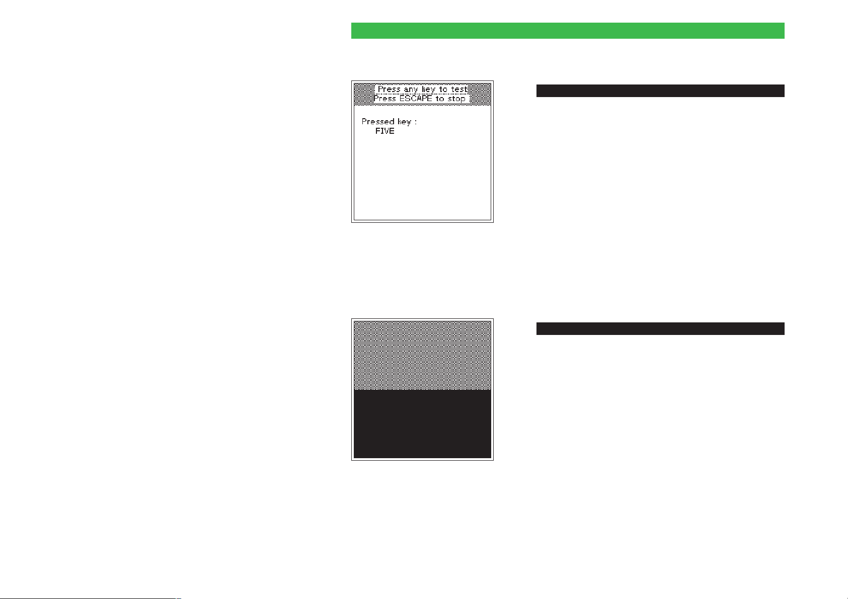
Keyboard test
ï
[SETUP] + Self check + [ENTER] + Keyboard test + [ENTER]
To test the keypad.
When you call this menu, the keyboard test starts
automatically.
! Press all the keys on your Willtek 4100 in succession.
If the display reports the designation of the key you
l
press, the key is OK. Numbers are written out (e.g.
FIVE).
If the display does not acknowledge a keypress, the
l
key is defective (e.g. corroded contacts following
ingress of liquid). In this case consult your sales
partner.
" Return with [ESCAPE].
Display test
ï
[SETUP] + Self check + [ENTER] + Display test + [ENTER]
To test the liquid crystal display.
When you call this menu, the display test starts
automatically.
l
The display is divided into two areas which alternate
between white, gray and black. These areas should
show no obvious dots or stripes.
l
If, for instance, you can see black dots or stripes in a
white area, the display is faulty. In this case, consult
your local Willtek sales office or authorized Distributor.
2-12
Return with [ESCAPE].
Page 29
Willtek 4100 Basic settings
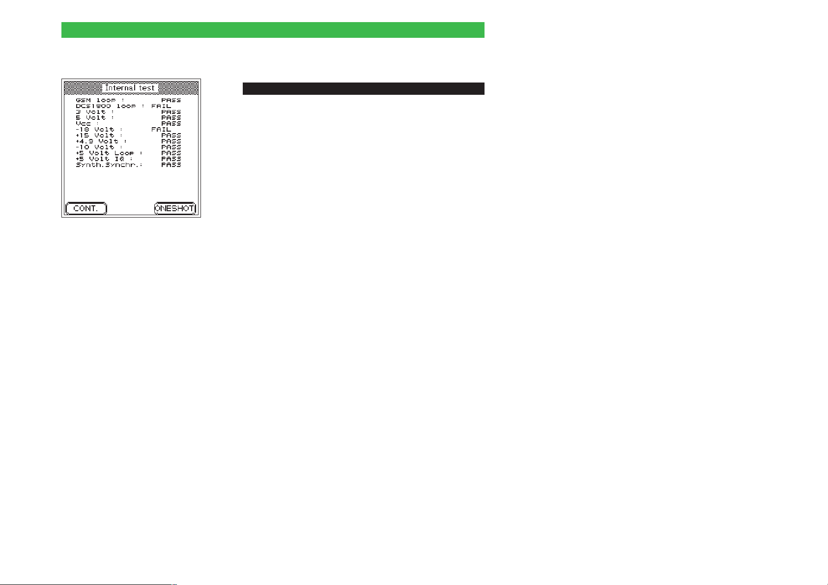
Internal test
ï
[SETUP] + Self check + [ENTER] + Internal test + [ENTER]
To run an internal test on important modules and
supply voltages.
! Press the {ONESHOT} softkey to start a single test run or
{CONT.} to start continuous testing (press {STOP} to
abort). PASS indicates that a test has been passed,
FAIL reports an error. With continuous testing, the
number of tests carried out and the total number of
errors detected are also reported.
Errors reported by tests may also be due to external
l
factors (such as major glitches in the line voltage). In
such cases repeat the test. If the errors recur, consult
your sales partner.
" Return with [ESCAPE]. Use {STOP} to abort continuous
testing first.
2-13
Page 30

Preparing the tests Willtek 4100
Preparing the tests
Preparations are identical for the tests in AUTOTEST
and FAULT FIND modes. They involve only two steps:
insertion of the test SIM in the test unit,
l
connection of the test unit to your Willtek 4100.
l
Installing the test SIM
Make sure that you insert the test SIM in the mobile
phone before carrying out an AUTOTEST. This is
because during the test, the Willtek 4100 will attempt to
perform measurements which are not generally
permitted by original SIMs. The test SIM is not
absolutely necessary for FAULT FIND mode, although
it is useful.
! Make sure the mobile phone is switched off.
2-14
Observe the equipment manufacturer's handling
instructions.
w
" Replace the original SIM with the test SIM. Plug-in
SIMs are usually hidden behind a small flap that you
see when you take out the battery.
Page 31
Willtek 4100 Preparing the tests
Do not forget to remove the test SIM before returning
an intact mobile phone. With the test SIM in the phone,
the customer will no longer be able to check into a
radio network; so even though the phone is intact, it will
be of no use to the customer.
Background information: SIM
n
The Subscriber Identity Module (SIM) contains the
subscriber identity code and is an exchangeable
component of any mobile phone. If there is no SIM, it is
not possible to set up a connection (except for
emergency calls). Some mobiles use smartcard-style
SIMs (full size), while others use the plug-in format.
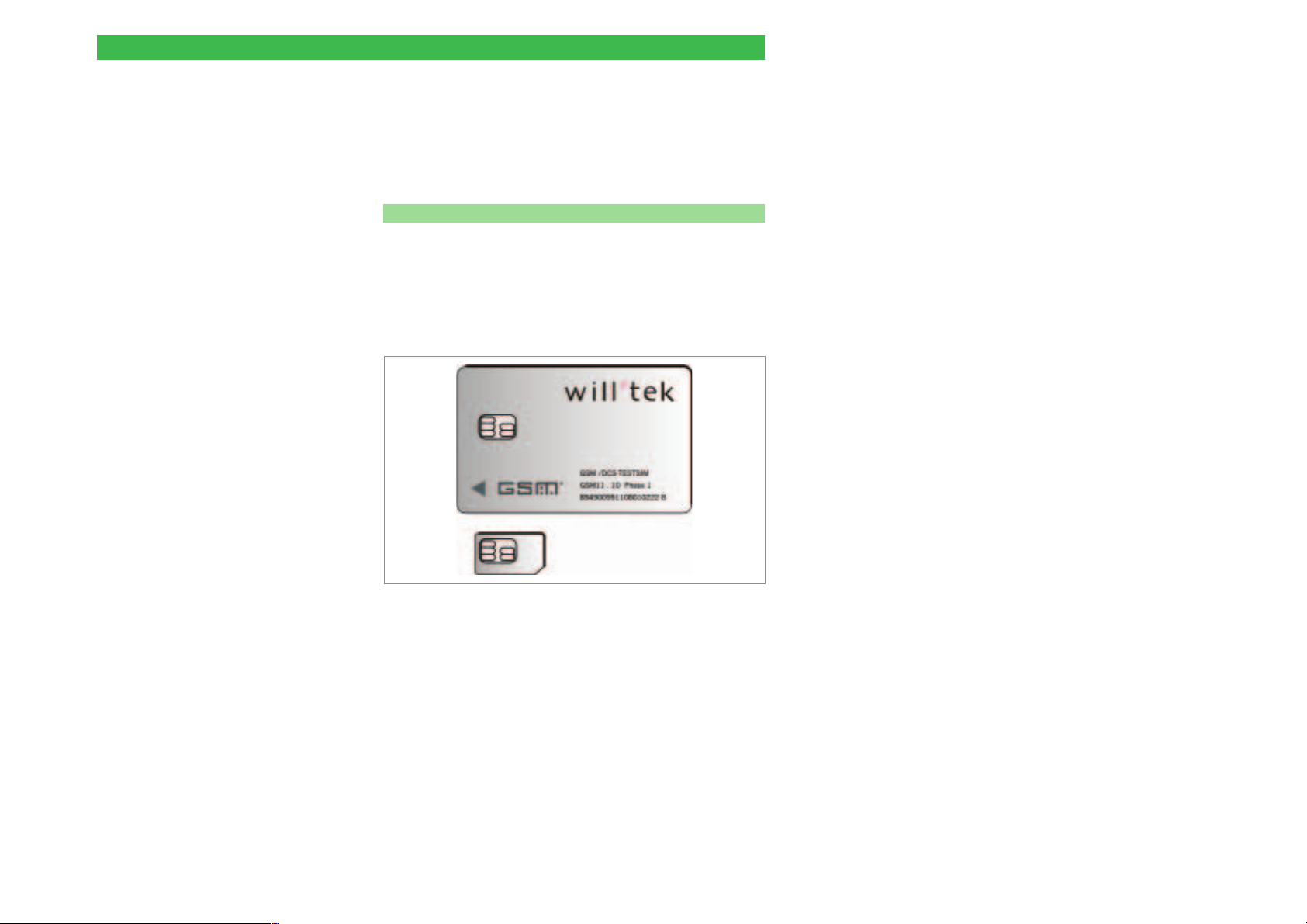
A full-size SIM (top) and a plug-in SIM.
Please note that the SIM card has an embedded
chip and the contacts to this can become
w
damaged with repeated flexing or a very large
number of insertions and removals from a mobile
phone.
2-15
Page 32
Preparing the tests Willtek 4100
Attaching the test unit
A WIlltek 4100 supports three methods of attaching a
mobile phone for testing:
wireless connection via antenna (extra accessory).
l
connection via the Universal Antenna Coupler (extra
l
accessory).
Cable-based connection via RF adapter cable and an
l
RF adapter which matches the phone (extra
accessory).
Connection via antenna
n Points in favor
max. approx. 50 cm
Very quick to set up.
l
Any GSM mobile phone can be tested.
l
The entire RF signal path of the phone is tested
l
(antenna included).
l
No RF adapter required.
Wireless connection of the test unit
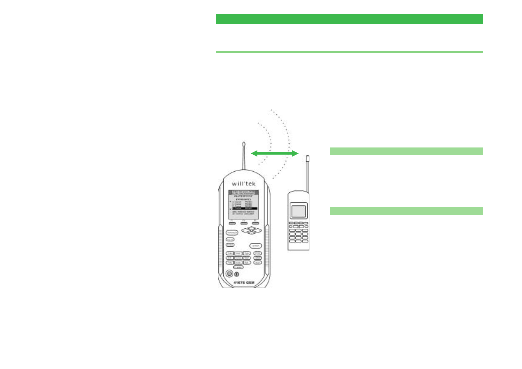
via antenna. The orientation of the two
antennas to each other is of no
particular significance.
2-16
n Points to note
l
Some tests call for clearly defined conditions
(accurately known RF input level at the radio's antenna
input). With a wireless connection, these particular test
values cannot be correctly measured (refer also to
page 3-17).
l
In order to keep RF signal attenuation in the space
between the devices to within reasonable bounds, the
distance between the tester and the mobile phone must
not exceed 50 cm.
l
Make sure that no conductive objects are lying between
the tester and the mobile phone (screening effect). The
two devices must not be placed on a conductive
surface.
l
Nearby base stations of a GSM mobile radio network
may cause the test results to be distorted.
Page 33
Willtek 4100 Preparing the tests
The radio is likely to get registered into a public mobile
l
radio network (unintentionally). Additional measures
must be taken at the start of a test run to ensure that
this does not happen.
Connection
n
Select the correct antenna for the mobile radio system
(extra accessory, see also page 6-38) which matches
the mobile phone frequency range and secure it to the
TNC connection of your Willtek 4100 by tightening the
coupling ring.
Do not use the wrong antenna, as this will falsify
+
the results of the test. The antenna for
GSM 900/E-GSM mobile phones has an overall
length of around 165 mm (6.5") and has two
yellow rings at the end. The antenna for
GSM 1800/1900 mobile phones is around
229 mm (9") in length and no rings at all.
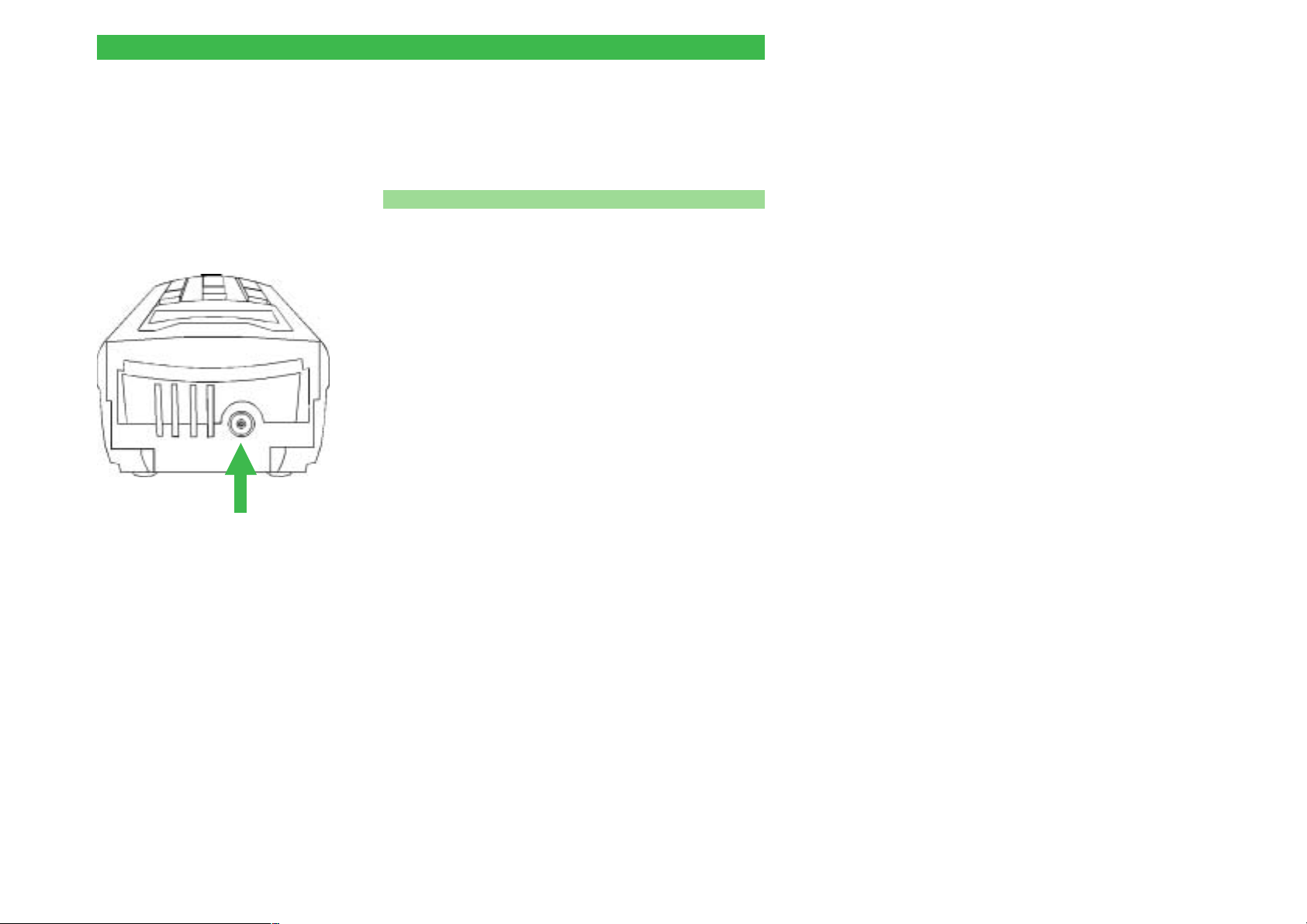
TNC connection
on Willtek 4100
2-17
Page 34
Preparing the tests Willtek 4100
Connection via the
Universal Antenna Coupler
Points in favor
n
The Universal Antenna Coupler is suitable for all radio
systems (GSM, PCN, PCS). It combines most of the
benefits of wireless connection via antenna with those of
cable-based connection. The more precisely defined test
conditions mean that measurements and tests which
were too inaccurate with the simple antenna connection
method are more reliable (refer also to page 3-17).
Points to note
n
The Universal Antenna Coupler can also react to
changes in the environmental conditions (such as the
proximity of a hand). Precision measurements can
therefore still only be performed with a cable-based
connection. RF interference from nearby base stations
can also create problems.
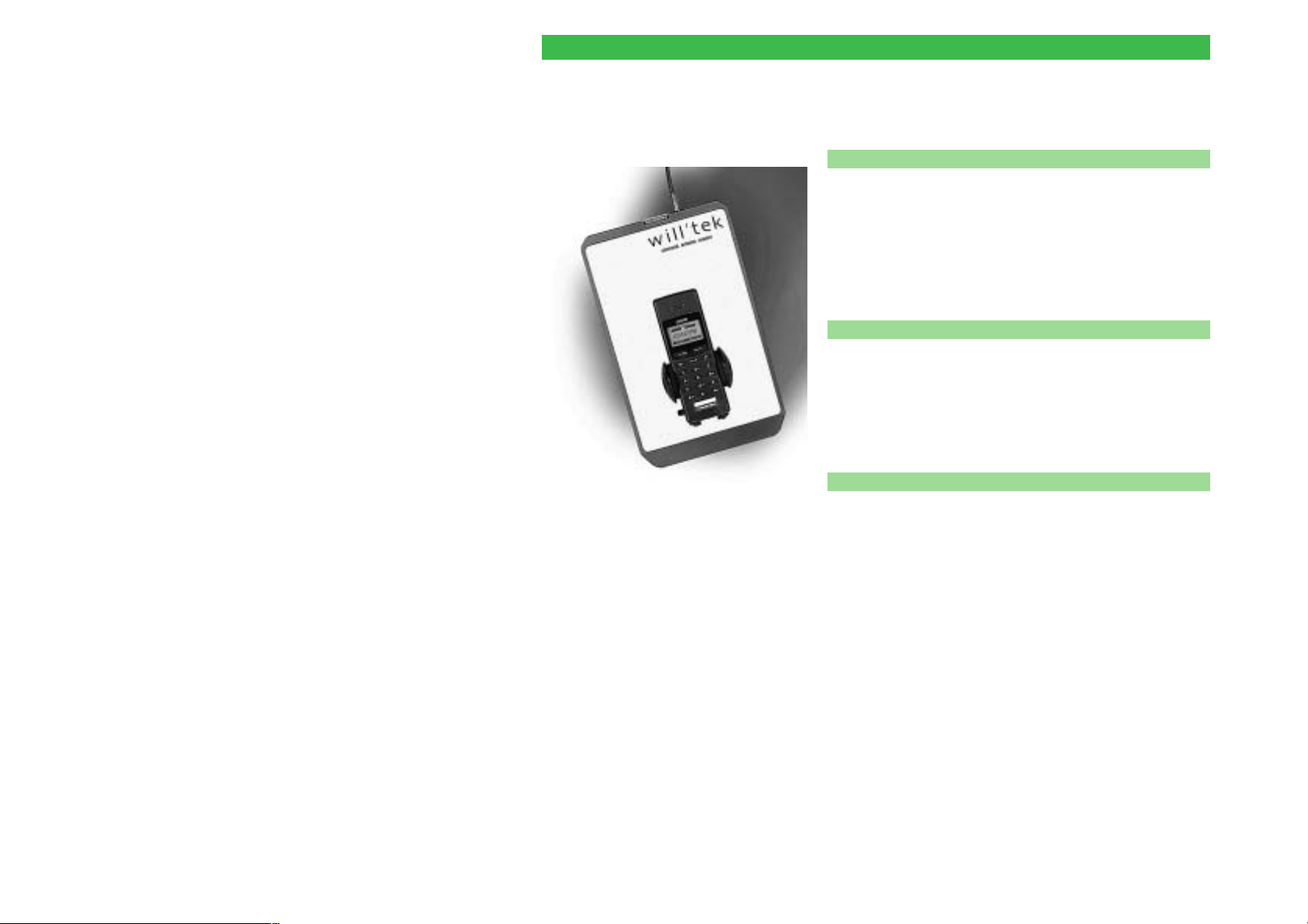
The important feature with the Universal
Antenna Coupler is that mobile phones of
the same type are always placed in exactly
the same position in the clamp.
2-18
n Connection
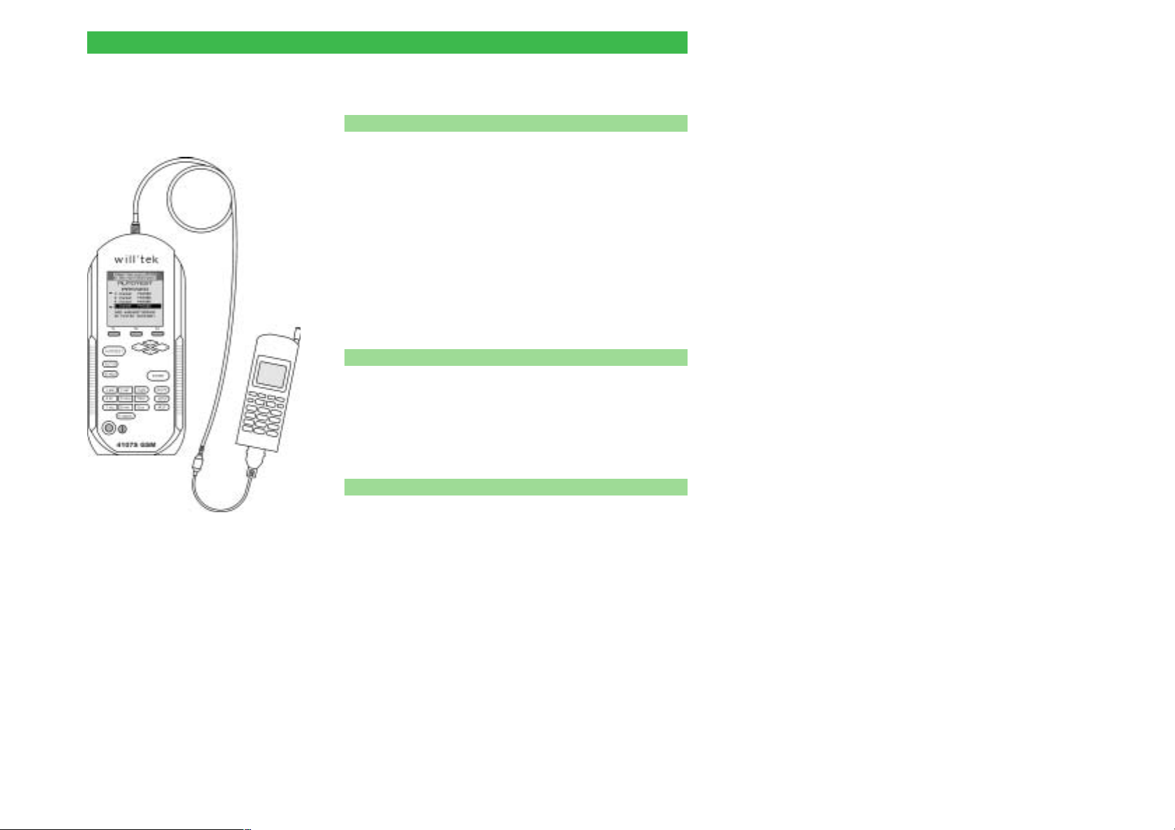
Connect the Universal Antenna Coupler to the
Willtek 4100 with the RF adapter cable supplied.
Release the jaws of the clamp by pressing small button
and insert the mobile phone in such a way that its
display points to the Willtek logo and the housing
touches the bottom restraint (see the figure lefthand).
Press the jaws of the clamp together firmly.
Make sure that mobile phones of one type are
+
always mounted in exactly the same position.
Only in this way can constant test conditions and
appropriate test results be guaranteed. If you
select an automatic start for an AUTOTEST, you
must observe any special instructions for the test
which may appear (e.g. fully extend the antenna
or check size of battery pack).
Page 35
Willtek 4100 Preparing the tests
Cable-based connection
Points in favor
n
RF adapter with cable coupling guarantees a set of
l
defined testing conditions. That means that all tests
produce results which can be correctly evaluated
against specifications.
As all the tests are suitable for evaluation, the
l
PASS/FAIL evaluation is more broadly based than with
wireless connection.
It is not possible for the test unit to (unintentionally)
l
register in a public mobile radio network.
There is no chance of interference from nearby GSM
l
base stations.
n Points to note
Test preparation takes longer.
l
Only mobile phones which have an RF connection
l
socket can be tested with this method.
l
Defects in the mobile phone's antenna circuit are not
detected.
Cable-based connection of the test
unit is the ideal choice for precision
measurements.
n Connection
Select the RF adapter (extra accessory) which matches
the mobile phone (see also page 6-40). First securely
attach the RF adapter cable (1.5 m) to the TNC
connection on the Willtek 4100 and to the RF adapter.
Then attach the mobile phone to the RF adapter. Use
original equipment only (otherwise you may risk false
readings).
When attaching the RF adapter, take great care
with the alignment of the contacts. Do not use
w
force. If an adapter does not fit properly, you may
have chosen the wrong one.
Make sure that there is good contact on all
plug-in connections (loose contacts lead to errors
in test results).
2-19
Page 36

Willtek 4100
§
AUTOTEST
3-1
Page 37

Overview Willtek 4100
Overview
An AUTOTEST performs a series of different
measurements largely automatically. By comparing its
measurements with stored target values, the
Willtek 4100 detects faults in the mobile phone. The
tolerances allowed with respect to the target values are
used to decide PASS or FAIL of each measurement.
At the end of the AUTOTEST, an overall evaluation of
PASSED or FAILED is derived from the evaluations of
the individual tests.
AUTOTEST
AUTOTEST
Testing without stress
A group of test parameters can be
assigned to any model of mobile
phone and then stored. Once the
parameters have been stored for a
given model, these preparatory steps
are no longer required if a further test
is carried out on the same model.
The AUTOTEST can be started
immediately. In these cases, the two
steps of preparing and running an
AUTOTEST are totally separate. The
advantage is that the two tasks can
be carried out at different times and
by people with different levels of
expertise.
PASSED The mobile phone is within the tolerances, and is in full
FAILED The mobile phone is outside the tolerances. The test
working order. There is no need for further
measurements in FAULT FIND mode.
unit is defective. Further measurements in FAULT
FIND mode can be used to identify the cause of the
fault (not available for Willtek 4107L).
n The influence of the user
Depending on the model, each Willtek 4100
incorporates at least one standard AUTOTEST as
supplied from the factory. In addition, it is possible to
read in user-defined AUTOTESTs. The user of a
Willtek 4100 cannot change the installed AUTOTEST
program, but can change the test parameters
(selection of channels, compensation of RF
pre-attenuation etc.). This allows local GSM channel
conflicts and model-specific RF measurement errors to
be eliminated. The AUTOTEST thus provides a reliable
evaluation of the mobile phone being tested.
Using the programming option "Utility Software" the
user can create user-defined AUTOTESTs, including
number, sequence or evaluation of the tests.
3-2
Page 38
Willtek 4100 Running an AUTOTEST
Running an AUTOTEST
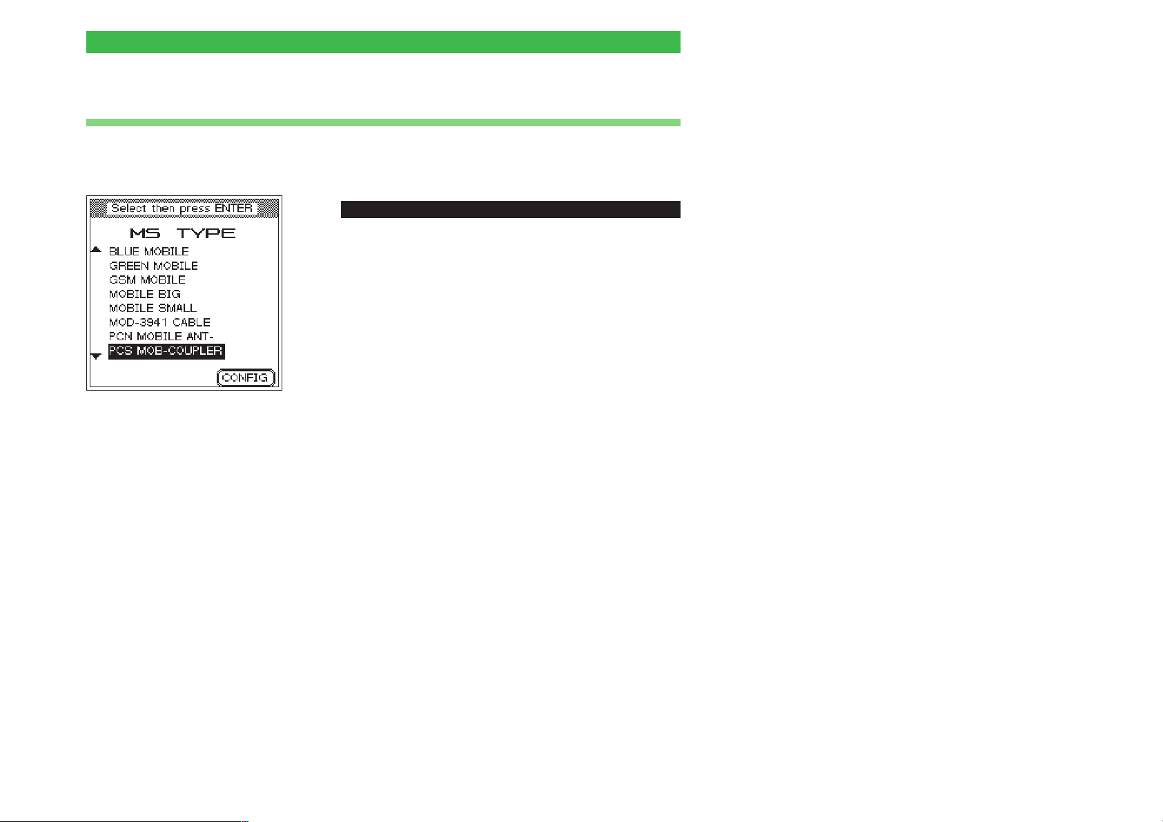
An AUTOTEST is always started in the same way: First
call the MS TYPE menu, then select the entry which
best matches the test unit.
The more accurately an entry in the
list characterizes a model, the less
risk there is of making an error.
The softkey has no significance
when starting AUTOTESTs (if it is
pressed by accident, you can
return to the MS TYPE menu by
pressing [ESCAPE]).
Be very careful to select the entry
which matches the test unit exactly.
It is possible that there are a num
ber of entries for a single model.
This can occur, for instance, if the
test unit is to be connected via the
Universal Antenna Coupler and dif
ferent battery packs are available
for this model. Since the thickness
of the battery pack has a consider
able influence on the measure
ments, it is quite common for there
to be a number of different entries
for a model in a case of this type.
-
-
ï
[AUTOTEST]
! With the cursor keys, select from the list exactly the
model you want to test (for details on adding a model to
the list, refer to page 3-13ff). A Willtek 4100 can store
up to 100 records of this type.
Fast search function: pressing a number key repeatedly
immediately places the cursor on the first entries which
start with the letters assigned to the key (for instance,
{7_stu] places the cursor alternately on the first entry
beginning with S, T or U).
" Switch off the mobile phone and install the test SIM
(refer to page 2-14). If the name of the model as shown
in the list already indicates the type of connection, then
connect the test unit as indicated (refer to page 2-16).
AUTOTEST only returns correct results if the
appropriate connection is used (antenna, coupler
w
or cable).
§ Start AUTOTEST by pressing [ENTER], switch on the
mobile phone and wait until the display on the mobile
phone shows the receiving signal strength or the ID of
the test network (11 or 00101). Now follow the
instructions on the display of the Willtek 4100. If the
-
-
required connection type has not been clear up to now,
it should be indicated at this point at the latest.
3-3
Page 39
Running an AUTOTEST Willtek 4100
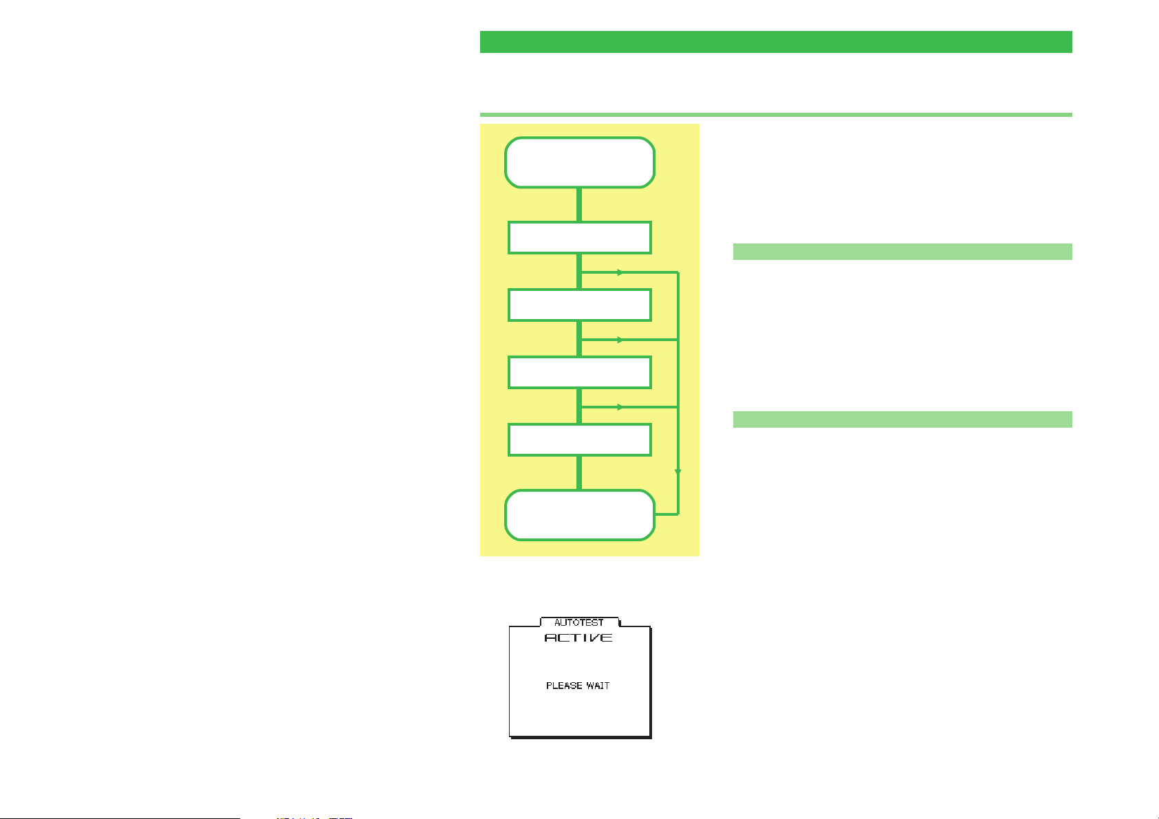
A Standard AUTOTEST is carried out as follows
The following description applies exclusively to the standard
Start
1st Input break
(MS CALL)
2nd Input break
(RELEASE)
3rd Input break
(BS CALL)
AUTOTEST, as this is the only test for which a binding and
pre-specified format exists. User-defined AUTOTESTs are
the sole responsibility of the programmers who created
them. They may resemble the standard AUTOTEST in
many ways, or differ quite considerably.
Be prepared for input breaks
n
A standard AUTOTEST will be interrupted some times
by breaks in processing, during which the Willtek 4100
prompts you on its display to perform a certain action.
The device waits as long as is necessary for you to
respond (no time limit). The message ACTIVE
displayed on the screen means that your Willtek 4100
is busy with the AUTOTEST and is not expecting an
input from you.
3-4
4th Input break
(Speech test)
Result
n When an AUTOTEST aborts
If you are quick with your inputs, a standard
AUTOTEST takes around 1 minute. If the message
AUTOTEST FAILED appears much earlier than this, it
is likely that a serious error has occurred which is
preventing further messages from being issued. An
error of this nature (e.g. during connection setup) will
result in the AUTOTEST aborting.
You can find out precisely which error led to the
AUTOTEST aborting by using the tester's error
analysis routine (see page 3-8).
If an AUTOTEST aborts with a message that there is
not enough main memory left, you will need to delete
some or all of the stored AUTOTESTs before running
another test (see page 3-12).
Press [ESCAPE] to cancel an AUTOTEST you have
started.
Page 40
Willtek 4100 Running an AUTOTEST
The input breaks of a Standard AUTOTEST
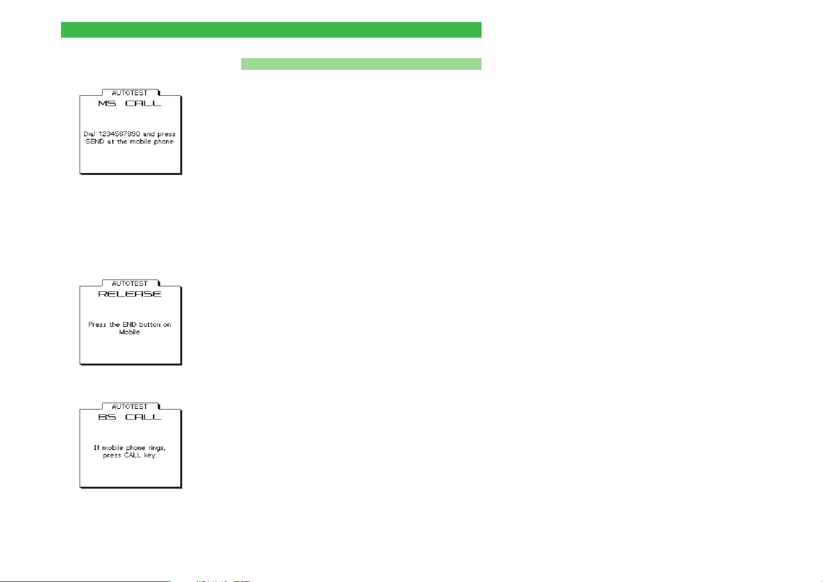
n
1st input During connection setup (MS CALL), the tester prompts
you to dial a number on the mobile phone.
Do not start to dial before the display on the
+
mobile phone shows either the receiving signal
strength or the ID of the test network (11 or
00101).
Dial 1234567890 on the mobile phone (note the
l
order!) and then press the button with function "Send".
The AUTOTEST now continues.
Dial the number correctly. If you miss any
+
numbers or enter them in the wrong order, the
result of the test will be FAILED!
2nd input Provided the AUTOTEST was not aborted owing to a
problem on the mobile telephone, another break occurs
just before the test to see whether a connection has
been set up correctly (hang up on mobile phone).
l
Press the button with function "Disconnect" on the
mobile phone (usually a button with a symbol of a
"hung-up" receiver). The AUTOTEST continues.
3rd input Provided the AUTOTEST was not aborted owing to a
problem on the mobile telephone, the tester – having
again set up a connection (this time BS CALL) – now
prompts you to take the call (incoming call from tester).
l
When the mobile phone rings and/or displays an optical
signal, press the button labeled CALL (usually the
same as the key function "Call"). The AUTOTEST
continues.
3-5
Page 41
Running an AUTOTEST Willtek 4100
4th input Provided the AUTOTEST was not aborted owing to a
problem on the mobile phone, the routine stops for the
last time at the speech test. This test does not produce
a positive result unless all the AF/RF components in
the mobile phone's send and receive paths are in full
working order.
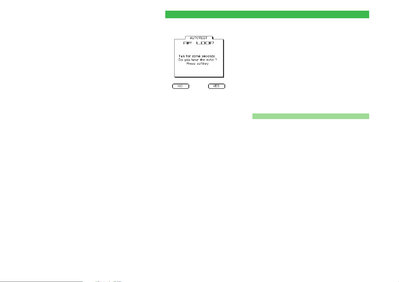
Say a single word into the mouthpiece of the phone. If
you hear a good quality echo after approx. 1 second,
press the {YES} softkey on the tester. If you do not hear
anything or if the echo is distorted, press {NO}. When
you have pressed one of the two softkeys, the
AUTOTEST proceeds without interruption to the end of
the routine, where it displays the test results.
n Lifting a tester block
In exceptional cases, defective mobile phones can
result in the tester no longer responding in the course
of an AUTOTEST. Should this happen, press [ESCAPE]
to cancel the test (a delay of up to 30 s is possible
before anything happens). If this does not lift the block,
switch off the tester briefly) and restart AUTOTEST.
3-6
Page 42
Willtek 4100 Results of the AUTOTEST
Results of the AUTOTEST
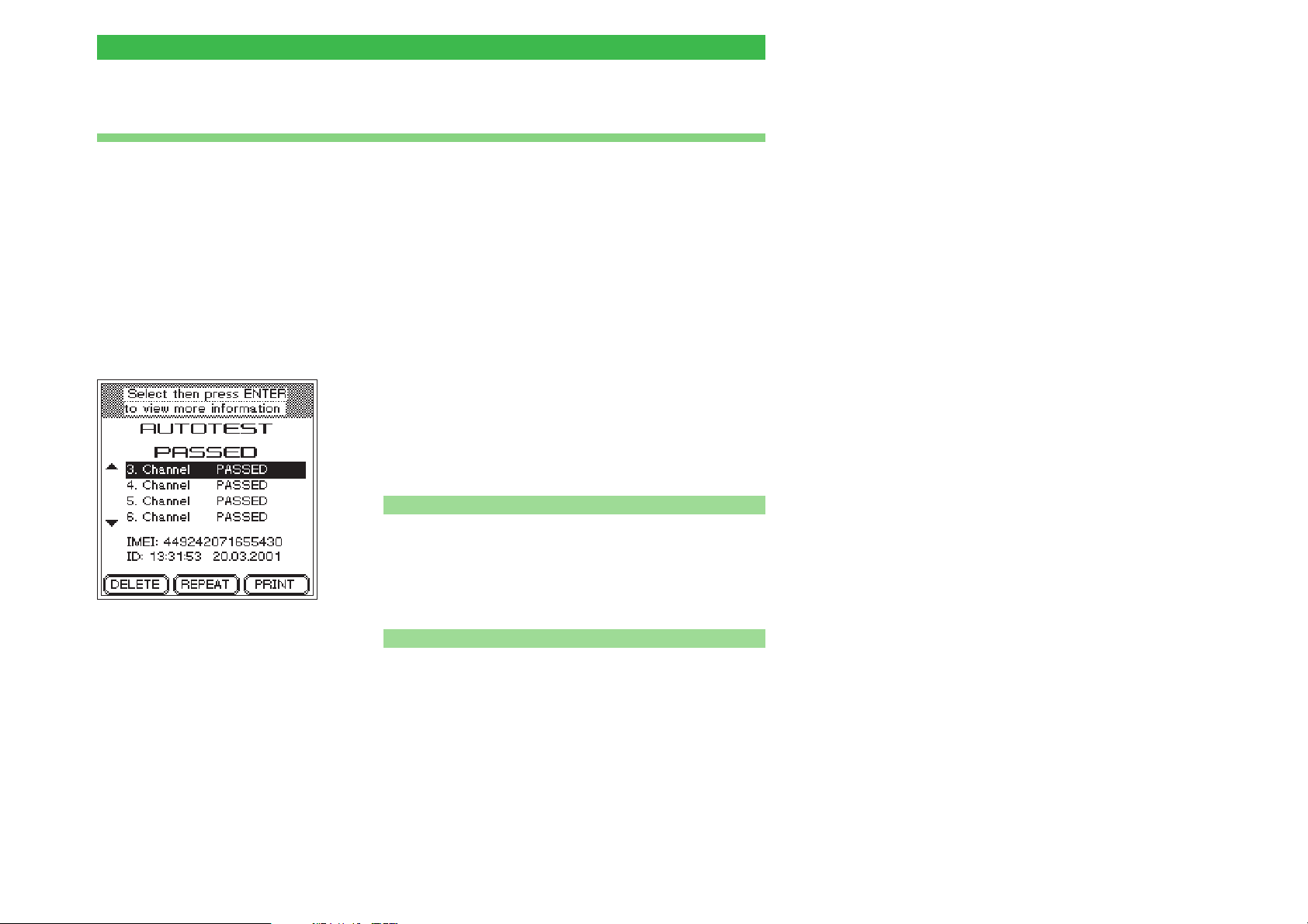
At the end of an AUTOTEST, the tester outputs a
AUTOTEST PASSED?
+
Do not forget to restore the
original SIM before returning
the mobile phone to the
customer. Otherwise the
customer will be unable to
use the phone and you will
not be able to continue
testing...
PASS/FAIL assessment for each voice channel tested
and the resultant overall assessment of PASSED or
FAILED. At the same time, the AUTOTEST log will be
stored in the tester under the ID number shown.
AUTOTEST PASSED
The mobile phone is within the permitted tolerances on
all tested channels. The tester has detected no faults.
The mobile phone malfunction of which the customer
has complained is not attributable to a technical defect
in the device.
It is highly likely that the malfunction is due to user error
or to bad reception (dead spots). Try to obtain a more
detailed description of the problem from the customer.
Evaluate later
+
Each log is
automatically given its
own ID number (time,
date). You can use this
ID in conjunction with
[TEST_RESULTS] to find
a log at a later point in
time, and then print it
out (see also
page 3-12).
n What to do if you are in doubt
If in doubt, repeat the AUTOTEST on other channels,
check that you prepared the test correctly, or switch to
FAULT FIND mode to check whether the phone is only
just within the allowed tolerances in a number of places
(FAULT FIND not available for Willtek 4107L).
n
Softkey functions
{DELETE} Deletes the log of the AUTOTEST you have just run,
then returns you to the MS TYPE menu.
{REPEAT} Repeats the AUTOTEST you have just run.
{PRINT} Prints a log of the most recent AUTOTEST (see
page 6-5 for general notes on printing).
Return to the MS TYPE menu with [ESCAPE].
3-7
Page 43
Results of the AUTOTEST Willtek 4100
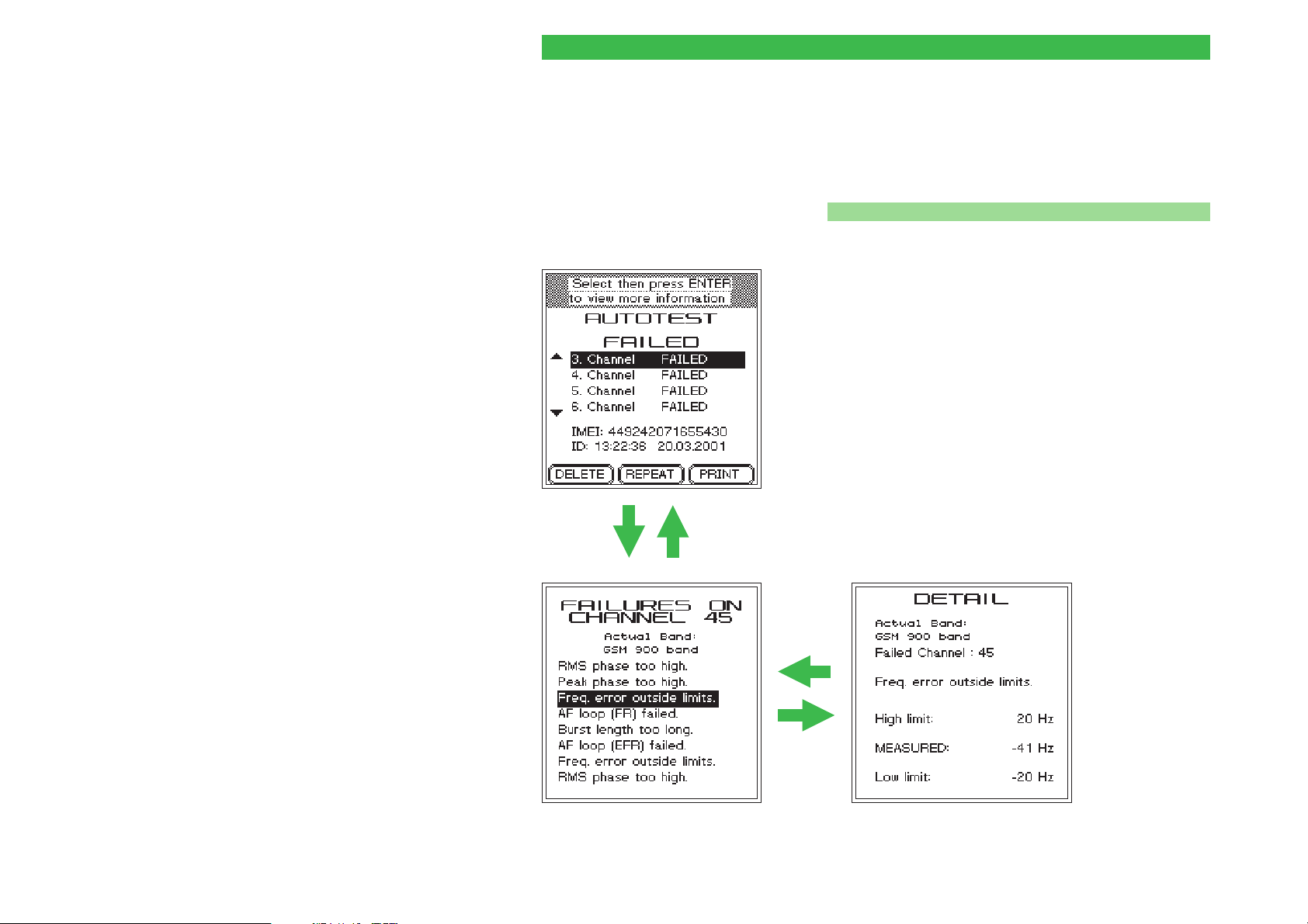
AUTOTEST FAILED
FAILED means that the mobile phone is outside the
permitted tolerances on at least one of the tested
channels.
Fault analysis
n
! Use the cursor keys to select one of up to 15 possible
FAIL entries.
" [ENTER] activates the first level of detail display. The
tester here shows the number of the defective channel.
The text also gives the assessments of all
measurements which are outside the permitted
tolerances.
Special case: The detail display of the 15th FAIL entry
Following Channels shows an asterisk in place of the
channel number (only possible with user-defined
AUTOTESTs). This occurs when more than 14
changes of channel are performed during an
AUTOTEST. The detail display for Following Channels
then groups together all the errors identified as of the
[ENTER]
[ESCAPE]
14th channel change. In this event, please refer to the
test log to assign the errors to the channel numbers.
[ESCAPE]
[ENTER]
First level of detail display Second level of detail display
3-8
Page 44

Willtek 4100 Results of the AUTOTEST
§ If you need more information, select more detail with
the cursor keys.
$ [ENTER] activates the second level of detail display.
The tester now shows the measurements on which the
selected assessment is based (including the tolerance
band limits).
% [ESCAPE] returns you to the next menu level up.
3-9
Page 45

Results of the AUTOTEST Willtek 4100
Sample AUTOTEST log (excerpt)
Willtek 4100 Mobile Tester Overall Test Result : FAILED
AUTOTEST: GSM Standard (GSM / E-GSM)
Test ID : 09:58:42 17.04.97
Mobile connection via : CABLE
IMSI : 001011234567890 IMEI : 490125513271390
MS Power Class : 4 (33 dBm) Revision level : Phase 1
Extended freq. : NO SMS : YES A5 : 1
Pre attenuation : 1.5 dB
RF output -60.0 dBm
Broadcast channel 63
Traffic channel 3
Power level 9 (25dBm)
Call from Mobile PASS
Dialled number PASS 1234567890 (1234567890)
Mobile release PASS
Broadcast channel 63
Traffic channel 27
Power level 5 (33dBm)
Call from Basestation PASS
Power Time template PASS
TX power PASS 35.1 dBm (29.0 - 37.0 dBm)
RMS phase PASS 3.63 deg (0.00 - 8.50 deg)
Peak phase PASS 9.68 deg (0.00 - 23.50 deg)
Freq. error PASS 12 Hz (-140 - 140 Hz)
Burst length PASS 559 us ( 543 - 563 us)
RX level FAIL * 63 ( 45 - 55)
RX quality PASS 0 ( 0 - 0)
RF output -80.0 dBm
Power level 9 (25dBm)
Power Time template PASS
TX power PASS 26.9 dBm (20.0 - 30.0 dBm)
RMS phase PASS 2.52 deg (0.00 - 8.50 deg)
Peak phase PASS 7.76 deg (0.00 - 23.50 deg)
Freq. error PASS -12 Hz (-140 - 140 Hz)
RX level FAIL * 42 ( 25 - 35)
RX quality PASS 0 ( 0 - 0)
RF output -96.0 dBm
BER PASS 0.00 % (0.00 - 0.30 %)
RF output -102.0 dBm
BER PASS 0.00 % (0.00 - 2.44 %)
RF output -80.0 dBm
Power level 14 (15dBm)
Traffic channel 123
TX power PASS 18.0 dBm (10.0 - 20.0 dBm)
RMS phase PASS 2.58 deg (0.00 - 8.50 deg)
Peak phase PASS 8.70 deg (0.00 - 23.50 deg)
3-10
Page 46
Willtek 4100 Evaluating stored AUTOTESTs
Evaluating stored AUTOTESTs
ï
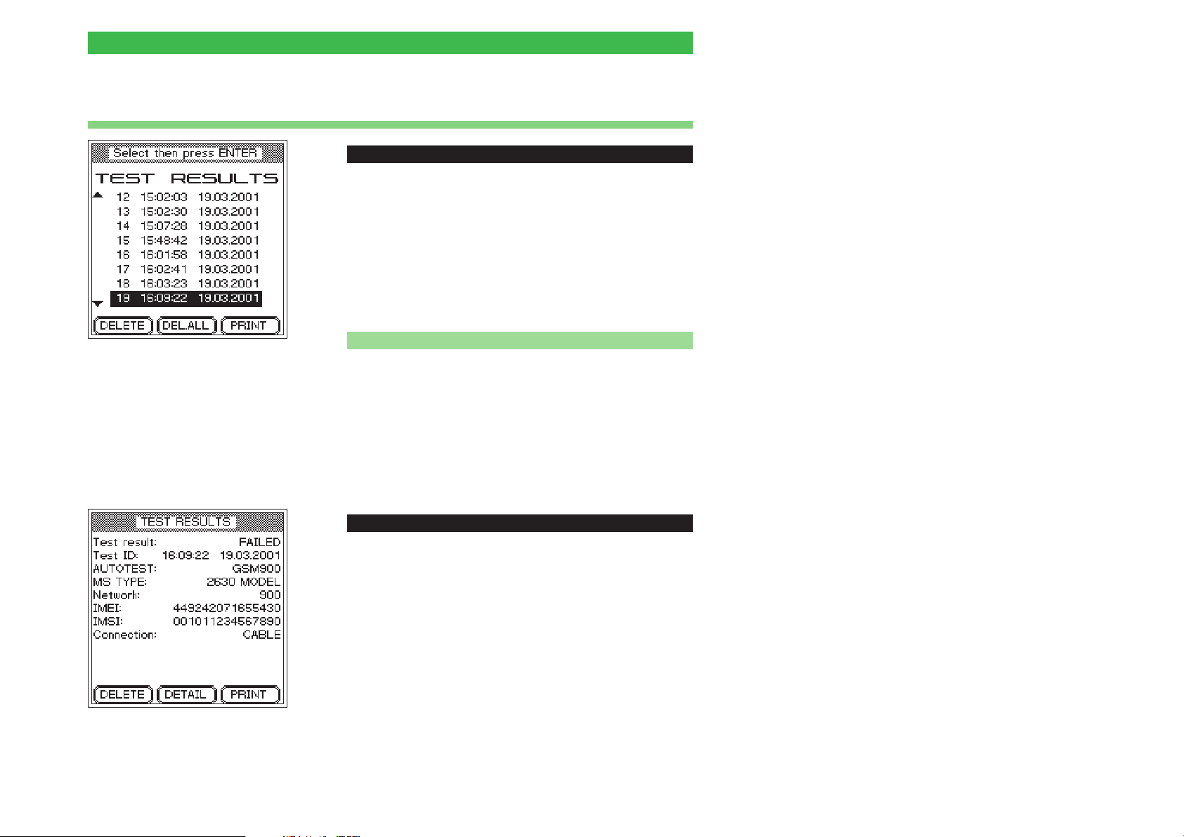
[TEST_RESULTS]
Provided you do not delete it the moment you have
finished running the AUTOTEST, a log will be stored in
your Willtek 4100 each time an AUTOTEST is run. The
tester automatically uses the date and time the
AUTOTEST was started as a means of identification
(ID). This ID appears at the bottom of each
AUTOTEST, and will help you locate a specific log at a
later point in time.
n Selecting a stored log
! Press [TEST_RESULTS] to display a list of AUTOTEST
logs you have stored.
" Use the cursor keys to select the ID (AUTOTEST) you
are looking for. A scroll arrow in the left-hand margin
indicates that there are more IDs outside the visible
area of the window. The [ó] and [®] cursor keys
place the cursor bar at the top and bottom of the list
respectively.
ï
[TEST_RESULTS] + Select ID + [ENTER]
§ Press [ENTER] to display a profile of the chosen
AUTOTEST log with its significant data. If this is the log
you are looking for, you can now either delete it or print
it out. Select [ESCAPE] to return to the list.
$ Select [AUTOTEST] or [FAULT_FIND] to return to the
mode you require.
3-11
Page 47
Evaluating stored AUTOTESTs Willtek 4100
Softkey functions
n
{DELETE} Deletes the AUTOTEST log currently selected (after a
confirmation prompt).
{DEL.ALL} Deletes all stored AUTOTEST logs (after a confirmation
prompt).
{DETAIL} Displays the results of the selected AUTOTEST as
described on pages 3-7 and 3-8 (including access to
the detail display). ESCAPE returns you to the TEST
RESULTS menu.
{PRINT} Prints the complete log of the AUTOTEST currently
selected (see page 6-5 for general notes about
printing).
n Available capacity for storing AUTOTESTs
There is space in the memory for approx. 300 standard
AUTOTEST logs. The actual number might be
considerably more or less than this in the case of
user-defined AUTOTESTs, which can vary in size.
When the memory is full, an error message is issued
the next time you attempt to run an AUTOTEST, or
while an AUTOTEST is in progress. If this happens,
you will need to free some capacity by deleting one or
more stored logs.
3-12
n
Downloading logs to a PC
If you want to avoid losing any logs, or intend to archive
logs for statistical evaluation at a later date, it is
worthwhile transferring saved logs to a PC (see
page 6-16).
Page 48

Willtek 4100 Entering test parameters
Entering test parameters
Correct test parameters are of key importance: On the
one hand, they prepare a model-specific AUTOTEST in
such a way that it can subsequently be started at the
touch of a button. On the other hand, the test
parameters can control an AUTOTEST in such a way
that the test results do not give errors from either
model-specific features or from local GSM channel
conflicts.
{DELETE} deletes the marked
record from the list.
{INSERT} allows you to create a
new record.
{MODIFY} allows you to edit the
marked record.
ï
l
l
l
l
[AUTOTEST] + {CONFIG}
The MS TYPE menu only shows entries for
+
which test parameter records have been created.
Entry of the test parameters involves only a few steps,
described on the following pages:
Assigning a name to the record
Selecting the radio system and the connection type
Selecting the required AUTOTEST
Entering the channel numbers and the
compensation values for RF pre-attenuation
As usual, the [ESCAPE] key returns you to the previous
menu while you are entering the test parameters.
Please note that the test parameters are valid
+
only for the type of mobile phone for which they
were entered. Models which vary only in their
construction (for example a different battery
pack) may need a new set of test parameters to
be created. This is particularly true for wireless
connections with the Universal Antenna Coupler.
3-13
Page 49
Entering test parameters Willtek 4100
1. Assigning a name to a record
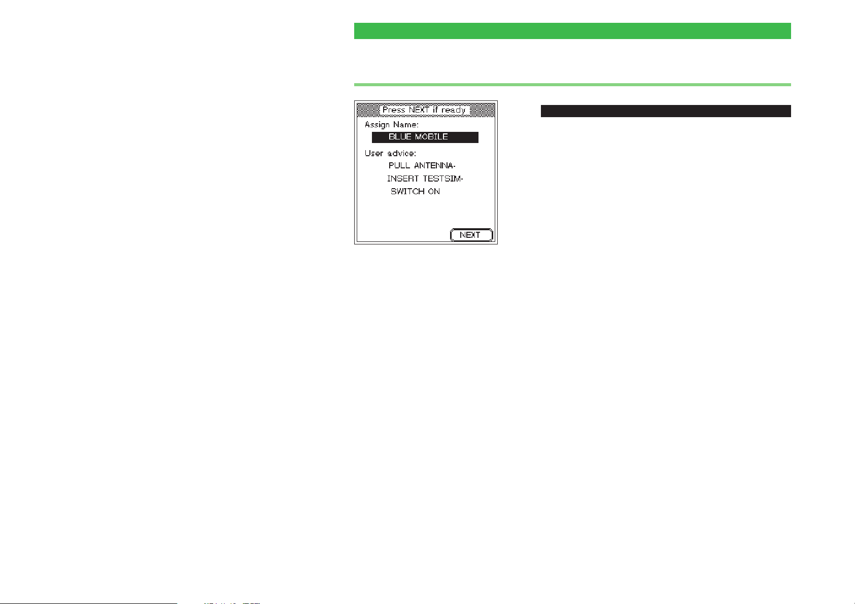
One line is available for the name
of the record (shown at the top)
and up to four lines are available
for user information (shown at the
bottom).
If other persons subsequently run
AUTOTESTs, you should always
provide detailed information.
Unclear or incomplete information
can lead to an inappropriate
AUTOTEST being started. If, for
instance, the connection type is not
clear without additional information,
you should indicate the correct
connection type, and it is best to do
this in the record name.
ï
[AUTOTEST] + {CONFIG} + {INSERT}
All the test parameters are stored in a single record,
which should be provided with a meaningful name (the
type of mobile phone for which the parameters are
valid). The name subsequently appears in alphabetical
order in the MS TYPE menu where it serves to directly
start model-specific AUTOTESTs.
In addition, you can enter a longer text which is
subsequently displayed immediately before the
AUTOTEST is started (for instance user information or
advice which is important for correct execution of the
test).
! Use the cursor keys to select the required input line.
" Enter the text letter by letter (digits are also allowed)
using the keys of the numeric keypad. Automatic text
entry also applies here (refer to page 2-6).
§ Press [ENTER] to confirm the text you have entered.
$ Use the cursor keys to move to the next input line and
enter text or proceed by pressing {NEXT}.
It should be noted that battery
packs of different thicknesses for
mobile phones can affect the
results. Depending on the model,
these can cause considerable
fluctuations in the measurements if
the Universal Antenna Coupler is
used.
3-14
Page 50
Willtek 4100 Entering test parameters
2. Selecting the radio system
ï
[AUTOTEST] + {CONFIG} + {INSERT} + {NEXT}
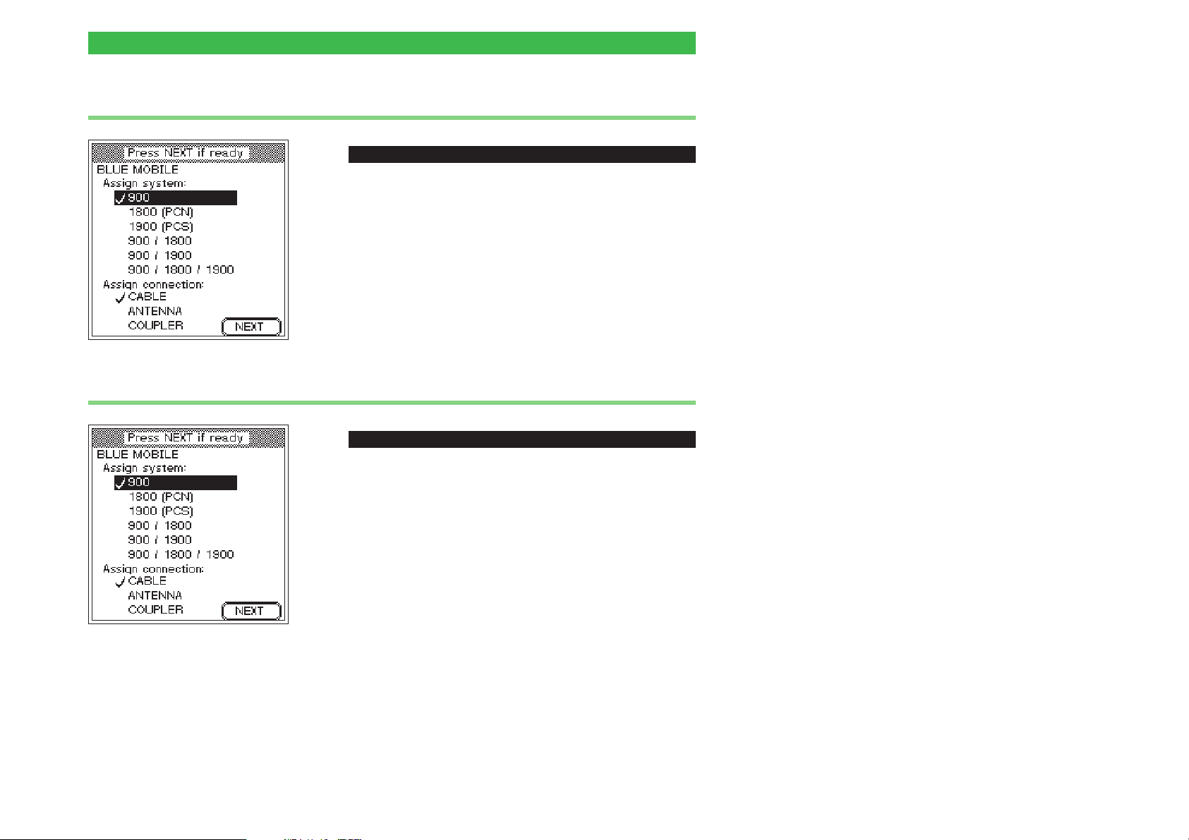
Select the radio system used by the mobile phone.
! Use the cursor keys to select the required system.
" Press [ENTER] to confirm your selection.
3. Selecting the connection type
ï
[AUTOTEST] + {CONFIG} + {INSERT} + {NEXT}
Select the type of connection to be used when the
mobile phone is subsequently tested. Refer to page
2-16ff for information on choosing the right connection.
! Use the cursor keys to select the required connection.
" Press [ENTER] to confirm your selection.
§ Press {NEXT} to proceed.
3-15
Page 51
Entering test parameters Willtek 4100
4. Selecting the AUTOTEST
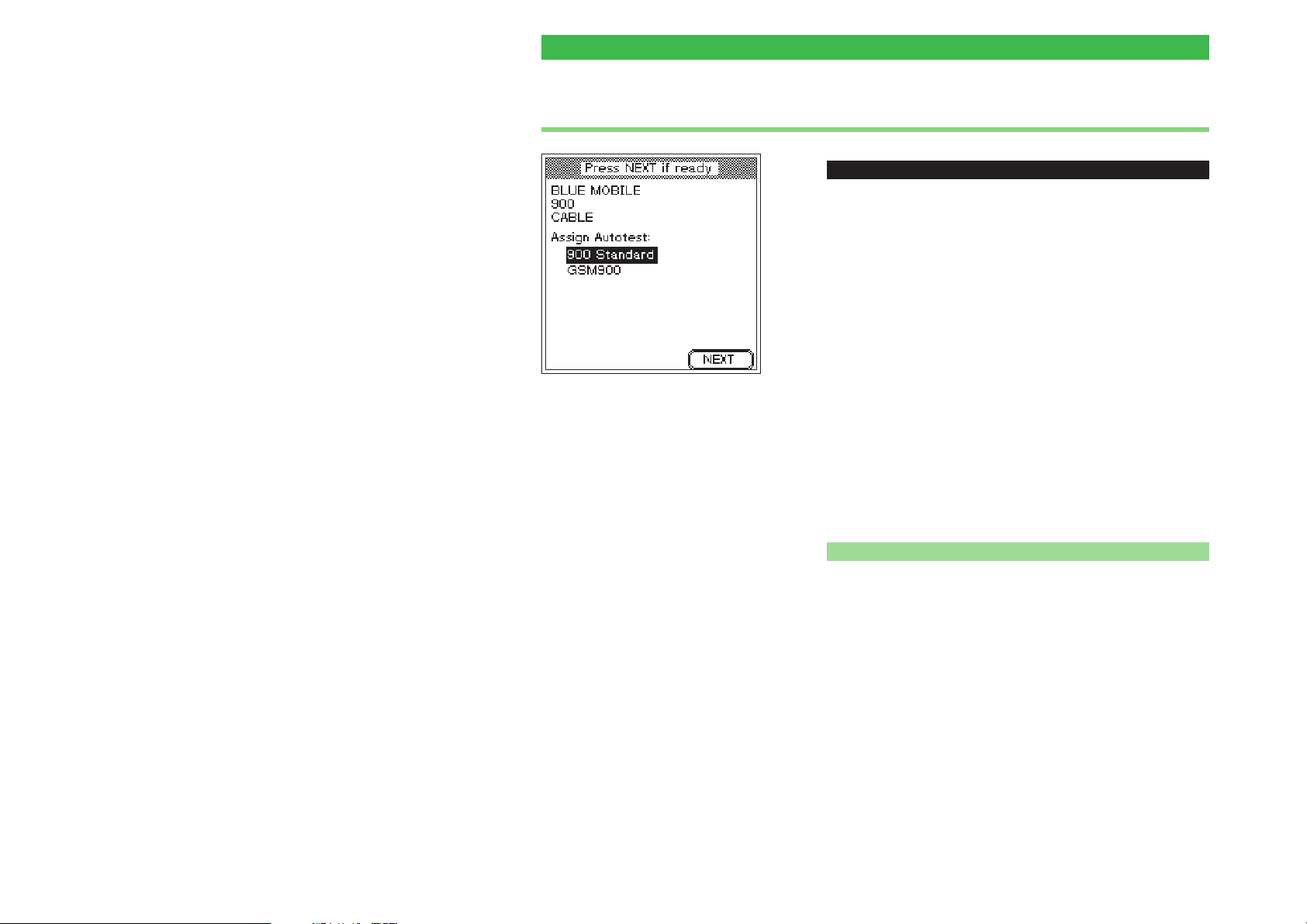
At the bottom of this menu only
those AUTOTESTs are listed which
match the test parameters listed at
the top of the display.
A Willtek 4107, for example, has at
least six AUTOTESTs stored (one
standard AUTOTEST for each
radio system). Since, however, the
"radio system" parameter for the
test is in this case 900, the
standard AUTOTESTS for the
other radio systems do not appear
in the list. In our example, however,
a further (user-defined)
AUTOTEST has passed the filter.
ï
[AUTOTEST] + {CONFIG} + {INSERT} +2x{NEXT}
The top part of this menu shows a summary of the test
parameters already set. This is important because the
bottom part of the menu does not simply list all the
AUTOTESTs stored in your Willtek 4100, but rather
lists only those which match the parameters for the
radio system and the connection. These two test
parameters filter out the matching AUTOTESTs from
those which are stored. The following section provides
information on the standard AUTOTESTs available ex
works. You will have to find the information on the tests
and measurements performed by a user-defined
AUTOTEST yourself.
! Use the cursor keys to select the required AUTOTEST
which will then be started when the mobile phone is
tested.
" Press {NEXT} to proceed.
n At least one AUTOTEST
If the list does not display the AUTOTEST you are
expecting, you should first check the two test
parameters. The standard AUTOTESTs available ex
works (one for each radio system) permit all three
possible variants for the connection test parameter. For
this reason, the list always shows at least the standard
AUTOTEST which matches the radio system test
parameter (e.g. GSM Standard). The word Standard
always follows the radio system in the names of
standard AUTOTESTs.
3-16
Page 52
Willtek 4100 Entering test parameters
Background: AUTOTEST
Any Willtek 4100 can store and run two variants of an
AUTOTEST:
Standard AUTOTESTs (installed at the factory)
l
User-defined AUTOTESTs (using the Utility Software option)
l
Standard AUTOTESTs
n
To make the correct choice in selecting AUTOTESTs,
you need to know what tests and measurements are
carried out during the routine. The table below provides
information on all the standard AUTOTESTs
(depending on the radio system). Please note the effect
of the connection type.
Applies only for standard AUTOTESTs
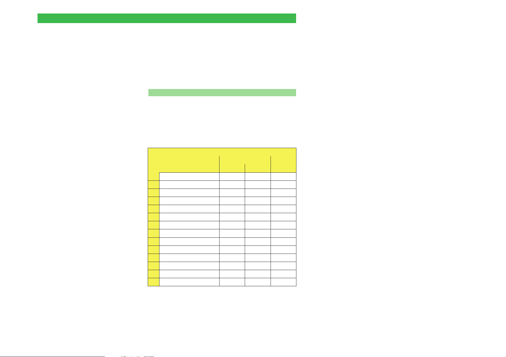
Test/measurement
RF output power
1
Bit error ratio (BER)
2
Frame erasure ratio (FER)
3
Phase error (RMS/peak)
4
Frequency error
5
RX level
6
RX quality
7
Power-time template
8
IMSI/IMEI
9
Antenna
10
Keypad
11
Call to/from mobile phone
12
Connection release
13
Audio loopback
14
Wireless
Antenna Coupler
üü
üüü
üüü
üü
üü
üüü
üü
üüü
üüü
üüü
üüü
Cable
ü
ü
ü
Depending on the connection type, certain tests are not
carried out, either because they are not possible (antenna
test for a cable-based connection) or because the result
would be unreliable due to external influences.
3-17
Page 53
Entering test parameters Willtek 4100
In all standard AUTOTESTs, PASS/FAIL evaluation of
PASS or FAIL
With standard AUTOTESTs, correct
FAIL evaluation requires the GSM limits
to be increased by the measurement
tolerances caused by physical
phenomena. This method is in common
practice and means that a mobile phone
which lies just outside the GSM limits
will be passed. At the same time, it is
not possible for a fully functional mobile
phone to be failed.
User-defined AUTOTESTs can allow for
design-specific features of mobile phones and thus make highly reliable
PASS/FAIL decisions.
the test results is based on the limits prescribed by
ETSI (European Telecommunications Standards
Institute) in its official "GSM Recommendations". If,
however, measurement tolerances are disregarded, it is
possible that a mobile phone which lies just inside the
limits may be failed incorrectly. To prevent this from
happening, standard AUTOTESTs use slightly larger
tolerance windows (GSM limits + measurement tolerance)
during evaluation.
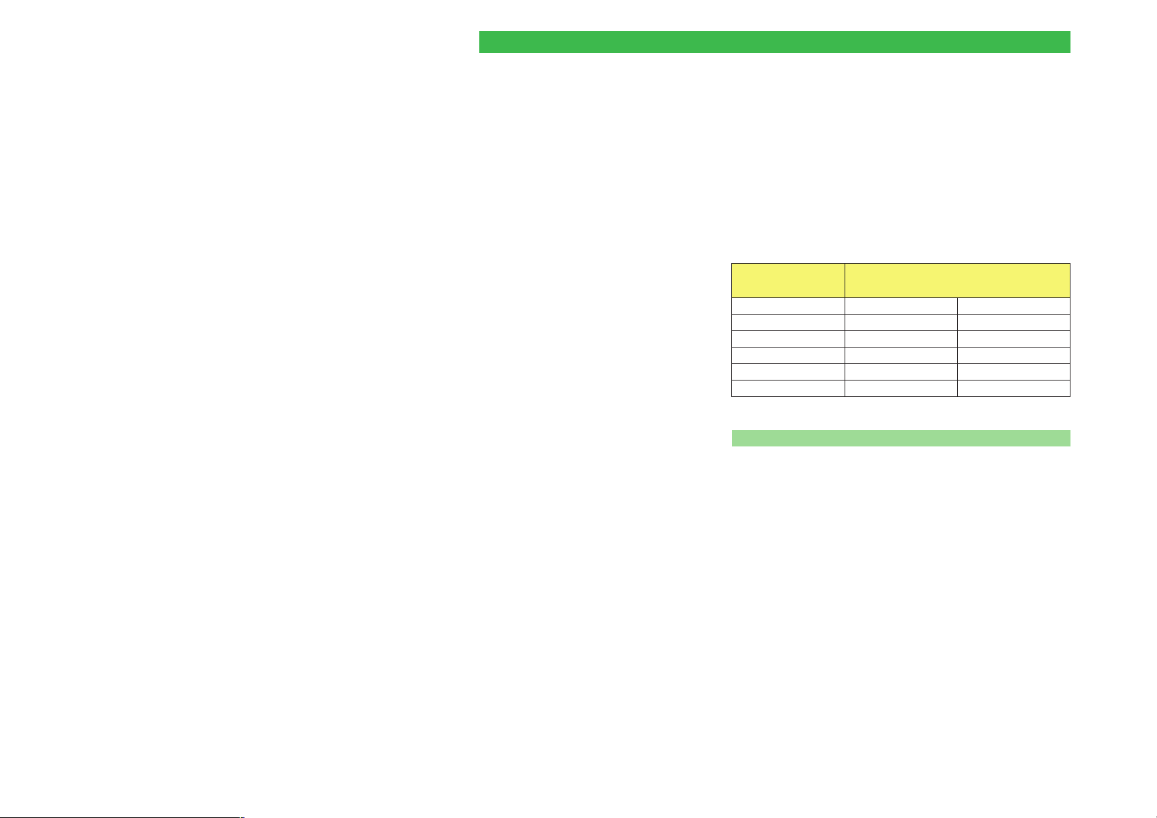
Measurement
RF Level ±2.0 dB ±2.0 dB
Peak Vector ±1.5 ° ±2.5 °
RMS Vector ±1.5 ° ±2.5 °
Frequency offset ±25 Hz ±50 Hz
Burst length ±0 ms ±0 ms
RX Sens ±2.0 dB ±2.0 dB
Added Measurement Tolerances
GSM900/E-GSM GSM1800/1900
n User-defined AUTOTESTs
The Utility Software (option 897 110) allows you to
create user-defined AUTOTESTs and load them into
the Willtek 4100 (see the User Guide for the 4100
Utility Software). Here you can modify the limits
governing PASS/FAIL evaluation and the number and
order of individual measurements. So-called "question
boxes" allow queries or instructions to be directed at
the user at any time during the execution of the test.
The user must then react to the question box (by
pressing a softkey) before the AUTOTEST continues.
3-18
A Willtek 4100 is able to store up to 20 user-defined
AUTOTESTs.
Page 54
Willtek 4100 Entering test parameters
5. Channel selection
Low – Middle – High
To ensure that frequency-dependent defects are not hidden, it is
advisable to choose three TCH
numbers which are evenly spread
out across the frequency band.
Multiband only
If, when selecting the radio system,
you have already selected a
multiband system (dual or triple
band), the above menu will be
shown two or three times for the
entries for each of the bands.
{NEXT} takes you to the next band.
When you reach the last band,
press the {OK} softkey to confirm
all the entries you have made and
pass the parameters to the tester.
ï
[AUTOTEST] + {CONFIG} + {INSERT} +3x{NEXT}
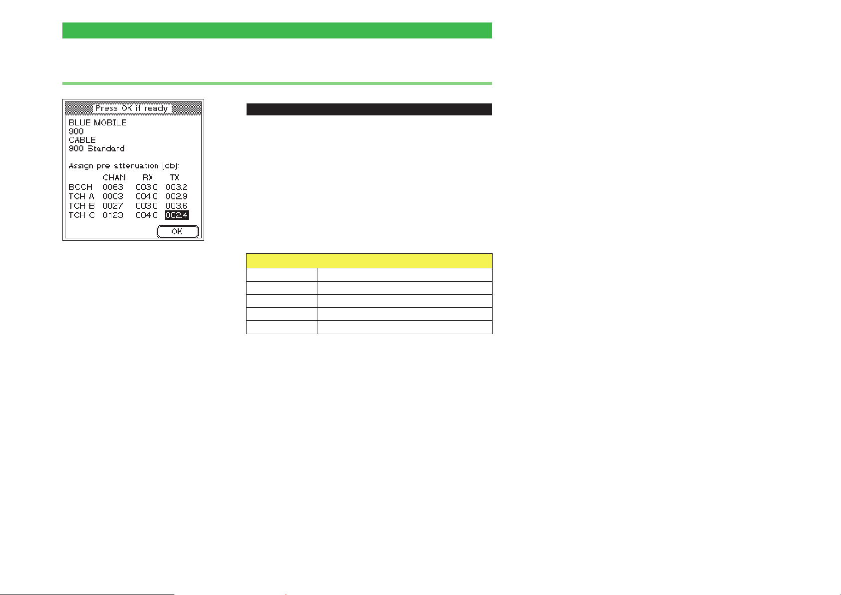
In this menu, you enter the numbers of the channels
which your Willtek 4100 will subsequently use to test
the mobile phone. One signaling channel (BCCH) and
three voice channels (TCH) are tested.
! Use the cursor keys to select the line you require in the
CHAN column (BCCH, TCH A, TCH B,orTCH C).
" Enter the channel number. Make sure that you do not
enter the same channel number twice.
Permissible channel numbers (BCCH and TCH)
GSM 0001 through 0124
E-GSM 0000 and 0975 through 1023
GSM-R 0955 through 0974
GSM 1800 (PCN) 0512 through 0885 (even numbers only)
GSM 1900 (PCS) 0512 through 0810 (odd numbers only)
§ Press [ENTER] to confirm your input. Invalid channel
numbers are detected and rejected.
$ Select the next channel and repeat the procedure. Do
not leave the menu when you have finished, since the
compensation values still have to be entered.
BCCH channel number: to avoid malfunctions
+
(particularly with wireless connection), do not use
the signaling channels of nearby base stations.
3-19
Page 55
Entering test parameters Willtek 4100
6. Entering compensation values
Are you using original Willtek
accessories for a cable-based
connection? Then you can simply
accept the factory settings for the
compensation values.
If the cursor is in one of the
columns RX or TX, the value at the
current cursor position can be
copied to all the fields below that
field using {COPY}. The {COPY} key
only appears if this method of
rapidly entering identical values is
feasible.
ï
[AUTOTEST] + {CONFIG} + {INSERT} +3x{NEXT}
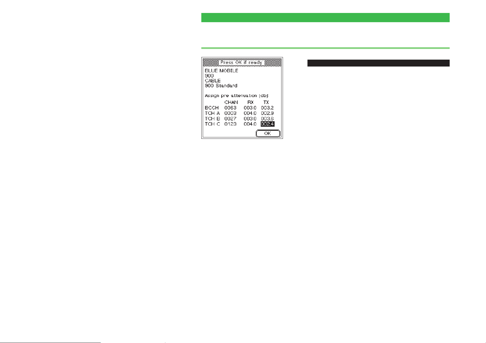
The last parameters you need to enter are the values
used to compensate for RF signal attenuation. To allow
correct RF level measurements at different frequencies,
this pre-attenuation can be compensated for separately
on the RX and TX signal paths for each channel (refer to
the section on "Background" for details).
! Use the cursor keys to move to the required input field
(RX or TX).
" Use the number keys to enter the overall attenuation of
the RF signal in decibels. When you start entering a
value, the softkey {OK} is assigned the new function
{DP} (for entering a decimal point).
§ Press [ENTER] to confirm your entry or use the {COPY}
key.
$ Select the next field and repeat the procedure
% Press {OK} to finish entering the test parameters. The
record is saved under the specified name. The
MS TYPE menu then appears in the display. Now you
can create another record for a different model of
mobile phone.
Incorrect compensation
values (which deviate from
w
the actual attenuation
values) distort those test
results which are based on
the value for the RF signal
level.
3-20
Background: signal attenuation
If a test unit is connected to the Willtek 4100, the
connection (cable, RF adapter or linear distance
between the antennas) will attenuate the RF signal.
This means that the mobile phone receives a signal
that is reduced by this attenuation, and the tester is
unable to measure the phone's actual output power.
False readings such as these can be avoided by
mathematically compensating for signal attenuation,
provided the attenuation value is known.
Page 56

Willtek 4100 Entering test parameters
Effect of the connection type
n
Universal Antenna Coupler The test conditions can be calculated to a sufficient
degree of accuracy to allow a meaningful
compensation. However, since the attenuation of
signals to and from the mobile and the coupler (signal
attenuation) is frequency-dependent, you must take the
receive and transmit paths into account. This is
because GSM radio systems transmit and receive in
different frequency bands (refer also to page 6-2). The
signal attenuation values can therefore fluctuate
considerably between the transmit and receive
directions. Compensation allows you to take account of
this by entering separate values for the RX and TX
paths.
The RF signal paths RX and TX always refer to the
mobile phone (rather than the tester):
RX Receive path of the mobile phone (corresponds
to the transmit path of the tester).
TX Transmit path of the mobile phone (corresponds
to the receive path of the tester).
Cable Compensation is set to an optimum value for
cable-based connection. This type of connection is not
frequency-dependent, so that it is not necessary to
distinguish between the receive and send paths of the
RF signal (RX/TX). The same compensation value is
valid for both paths.
Antenna Compensation is meaningless for a simple antenna
connection. External influences have such a wide effect
on RF signal attenuation that compensation does not
improve the accuracy of measurements.
3-21
Page 57
Entering test parameters Willtek 4100
Determining compensation values
Since simple antenna connection is of no relevance
here, we only need to consider compensation values
The Universal Antenna Coupler can be
used with other test equipment and
also for analog phones.
for the remaining two connection types. If you are using
a cable-based connection, it is very simple to determine
the compensation values.
Precautions are necessary to avoid
interference, and the test equipment
needs to have an RF power offset
facility of at least 15 dB for displayed
values to be valid after correction.
Deviations of up to 20 dB
Measurements performed in the Willtek
laboratories have shown that the
coupling attenuation of the Universal
Antenna Coupler depends to a large
degree on the model of the mobile
phone (deviations of up to 20 dB).
Battery packs of different thicknesses
and the degree to which the antenna is
extended have a significant effect on
the coupling attenuation value. For this
reason, it is impossible to provide a
compensation value which is valid for
all types of phones, battery and
antenna combinations.
Cable-based connection
n
In this case, it is sufficient to enter a fixed
compensation value in the RX and TX entry fields:
1.5 applies for GSM/E-GSM
2.0 applies for PCN (DCS1800)/PCS (DCS1900)
Values are identical for the RX and TX signal paths,
since a cable-based connection is not
frequency-dependent. Please note that these values
only apply if you are using Willtek original accessories
(cable, RF adapter).
n Universal Antenna Coupler
Fortunately, you do not need an RF signal generator
and monitoring decoder to derive the compensation
values for the coupler. In practice, a Willtek 4100 and a
correctly functioning mobile phone are sufficient for the
job.
! Secure the mobile phone in the clamp on the Universal
Antenna Coupler.
" Create a record for the mobile phone with appropriate
test parameters. For the connection method, select
COUPLER, choose the standard AUTOTEST listed and
enter the value 0 in all the entry fields for the RX and
TX compensation values.
§ Start an AUTOTEST using the record you have just
created and then print the test log. If FAIL comments
appear, this is due to the 0 dB compensation values
and should be disregarded.
3-22
Page 58
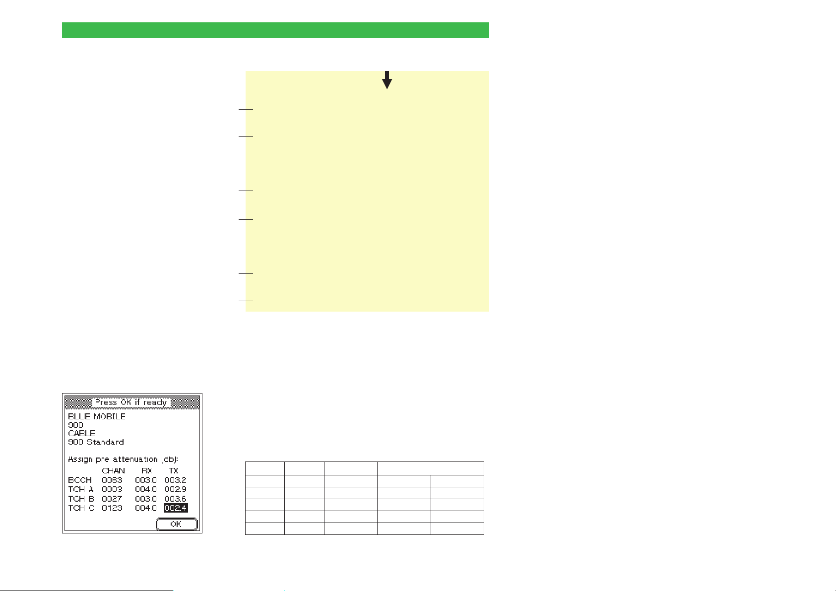
Willtek 4100 Entering test parameters
Measurements
Traffic channel 3
Power level 9 (25dBm)
Call from Mobile PASS
Dialled number PASS 1234567890 (1234567890)
Power Time template PASS
TX power PASS 22.1 dBm (20.0 - 30.0 dBm)
RMS phase PASS 3.63 deg (0.00 - 7.50 deg)
Peak phase PASS 9.68 deg (0.00 - 22.50 deg)
Freq. error PASS 12 Hz (-115 - 115 Hz)
Burst length PASS 559 us ( 543 - 563 us)
RX level PASS 26 ( 25 - 35)
RX quality PASS 0 ( 0 - 0)
Mobile release PASS
Broadcast channel 63
Traffic channel 27
Power level 5 (33dBm)
Call from Basestation PASS
RF output -80.0 dBm
Power Time template PASS
TX power PASS 29.4 dBm (28.0 - 38.0 dBm)
RMS phase PASS 3.63 deg (0.00 - 7.50 deg)
Peak phase PASS 9.68 deg (0.00 - 22.50 deg)
Freq. error PASS 12 Hz (-115 - 115 Hz)
Burst length PASS 559 us ( 543 - 563 us)
RX level PASS 25 ( 25 - 35)
RX quality PASS 0 ( 0 - 0)
RF output -96.0 dBm
BER PASS 0.00 % (0.00 - 0.30 %)
RF output -102.0 dBm
BER PASS 0.00 % (0.00 - 1.50 %)
FER PASS 0.08 % (0.00 - 0.10 %)
RF output -80.0 dBm
Power level 14 (15dBm)
Traffic channel 123
TX power PASS 12.6 dBm (10.0 - 20.0 dBm)
RMS phase PASS 2.58 deg (0.00 - 7.50 deg)
Peak phase PASS 8.70 deg (0.00 - 22.50 deg)
Freq. error PASS -52 Hz (-115 - 115 Hz)
AF loop PASS
RX level PASS 27 ( 25 - 35)
Basestation release PASS
Depending on the radio system
and the type of connection, it is
possible that the log will differ
from the example shown on the
right (GSM). The only important
values are the TX power and
RX level lines which appear in
the log once for each traffic
channel.
A1
A2
B1
B2
C1
C2
$ In your log, identify the six lines marked in the extract
from the sample log shown above and make a note of
the measurements (e.g. A1 = 22.1) and the
corresponding TCH channel number.
% Use the difference table below to derive the
compensation values. Replace the values A1 through
C2 with the relevant measurements. The table is
structured in the same way as the menu in which you
enter the compensation values. All you have to do is to
enter the results in the corresponding fields.
CHAN RX TX
GSM/PCN/PCS GSM 900 only PCN/PCS
BCCH
TCH A 30–A2 25–A1 12–A1
TCH B 30–B2 33–B1 20–B1
TCH C 30–C2 15–C1 2–C1
3-23
Page 59
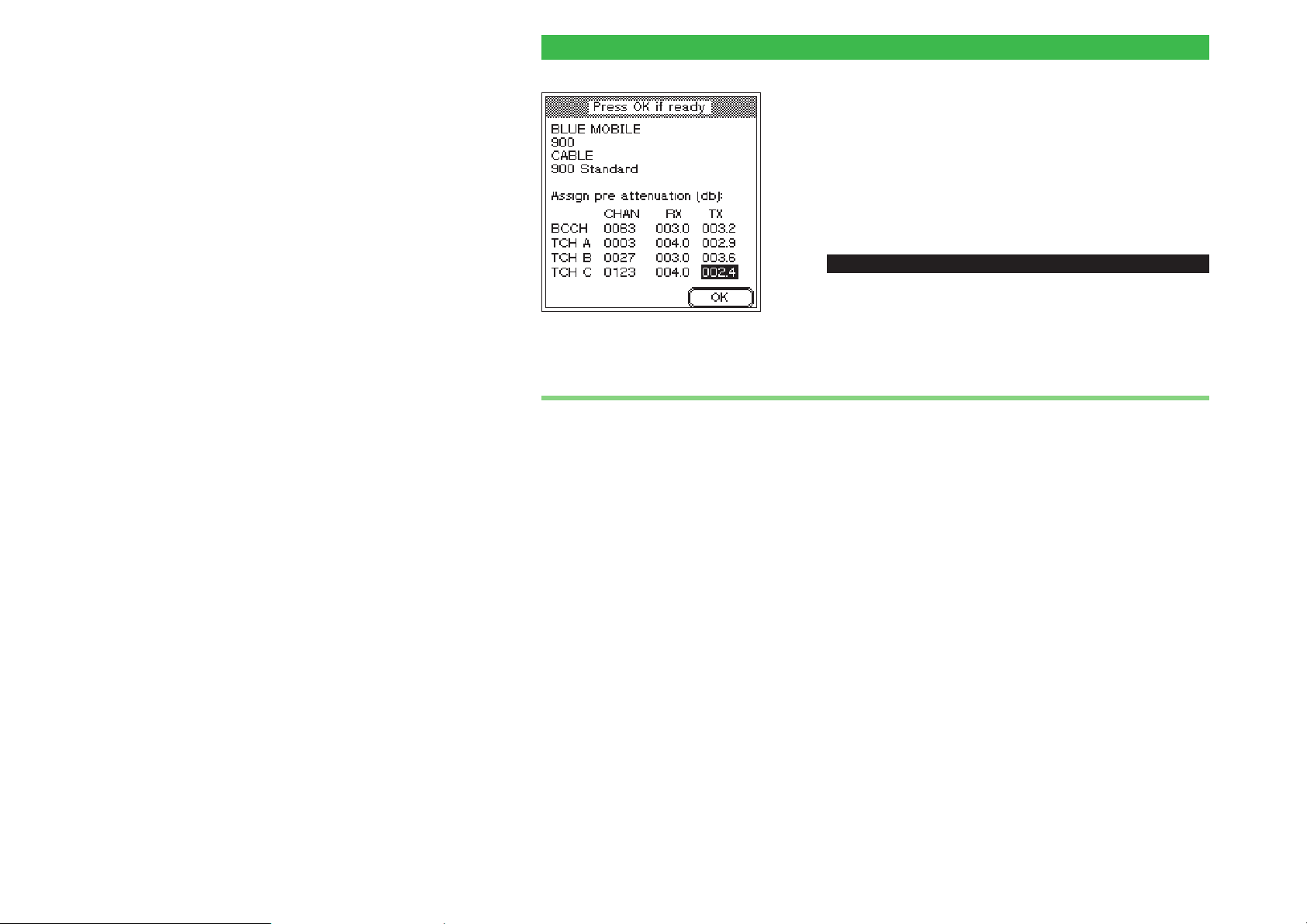
Entering test parameters Willtek 4100
For the BCCH signaling channel, you should use the
values of the nearest TCH channel (this approximation
is permissible since no RF measurements are carried
out on the BCCH channel).
& In the MS TYPE menu, select the appropriate record
for the mobile phone and correct the compensation
values there. Then save the record by pressing {OK}.
Copying records
ï
[AUTOTEST] + {CONFIG} + {MODIFY} +3x{NEXT}
The "4X00 Data Exchange" program allows you to copy
all MS TYPE records and AUTOTESTs to a different
Willtek 4100 (see also page 6-14). Alternatively, you
can save a copy of the records on your PC's hard disk,
so that you can revert to this backup in the event of
data loss.
During the copy operation, all MS TYPE records
and AUTOTESTs on the target tester will be
w
overwritten!
4X00 Data Exchange (de4X00.exe) is provided on
the accompanying CD. The current version is available
on the Internet:
http://www.willtek.com
3-24
Page 60

Willtek 4100
$
FAULT FIND
4-1
Page 61
Overview Willtek 4100
Overview
In FAULT FIND mode you have access to all the tests
that a Willtek 4100 is capable of performing. This
includes those tests which are run automatically in
AUTOTEST mode. You can also add further tests, and
numerically displayed measurements help you to
selectively identify important quality parameters of a
mobile phone.
The mode for experts
In FAULT FIND mode as opposed to AUTOTEST mode
there is no automatic PASSED/FAILED evaluation of
the test results. That means that FAULT FIND tests are
more suitable for experts who want to pinpoint the
In FAULT FIND mode a Willtek 4100
shows its sophisticated test capability;
but correct interpretation of the test
results and measurements does
demand a certain amount of expertise
with GSM and measurement
techniques.
source of faults on the basis of individual test results
and measurements.
The FAULT FIND mode is not available for the
+
Willtek 4107L model.
4-2
Page 62
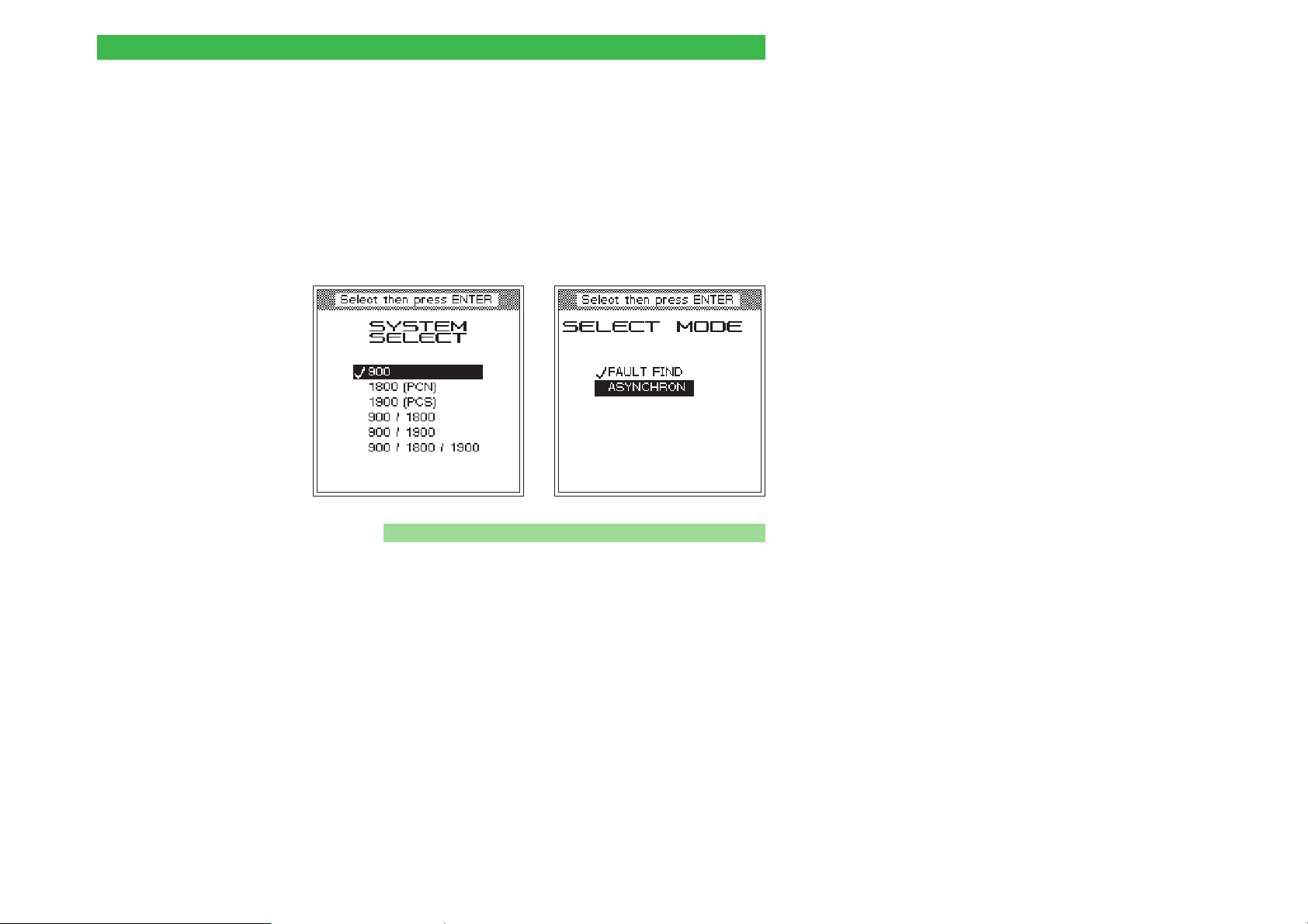
Willtek 4100 Overview
Accessing FAULT FIND mode
Regardless of which menu is currently open, pressing
the [FAULT_FIND] key calls up the first menu of the
FAULT FIND mode (provided that the tester is passive
and is not maintaining a connection to a mobile phone).
Which menu is the first depends on which model in the
Willtek 4100 series you have (see below).
Willtek 4107
n Access with the Willtek 4107S
In the Willtek 4107S only, the additional SELECT
MODE menu is used to access FAULT FIND mode:
Use the cursor keys to select the entry FAULT FIND
and confirm your selection with [ENTER].
ASYNCHRON: see Chapter 5
Willtek 4107S
4-3
Page 63
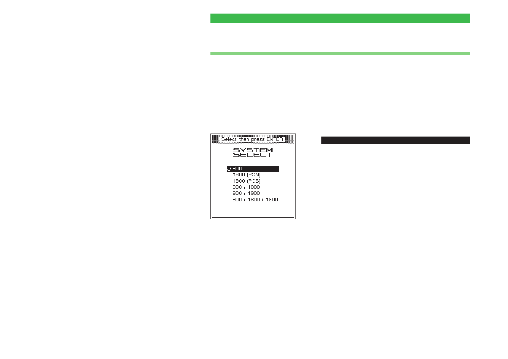
FAULT FIND test preparation Willtek 4100
FAULT FIND test preparation
Test preparation in FAULT FIND mode involves a
maximum of five actions:
selecting the radio system
l
selecting channels/RF power
l
compensating for signal attenuation
l
installing the test SIM (only if necessary)
l
Connecting the mobile phone
l
ï
Any menu + [FAULT_FIND]
Selecting the radio system
Willtek 4107 and $4107S are able to carry
out tests on mobile phones using different GSM radio
systems. Therefore, for these models only, test
preparation starts with the selection of the radio
system.
! Position the cursor on the radio network to which the
mobile phone belongs. The menu lists the generic radio
network names, the radio systems. The actual names
of the radio networks vary from country to country and
generally have nothing at all to do with the generic
names.
" Press [ENTER] to confirm your selection. When you do
so, the FAULT FIND menu for selecting the test
channels and the RF power is opened.
4-4
Page 64
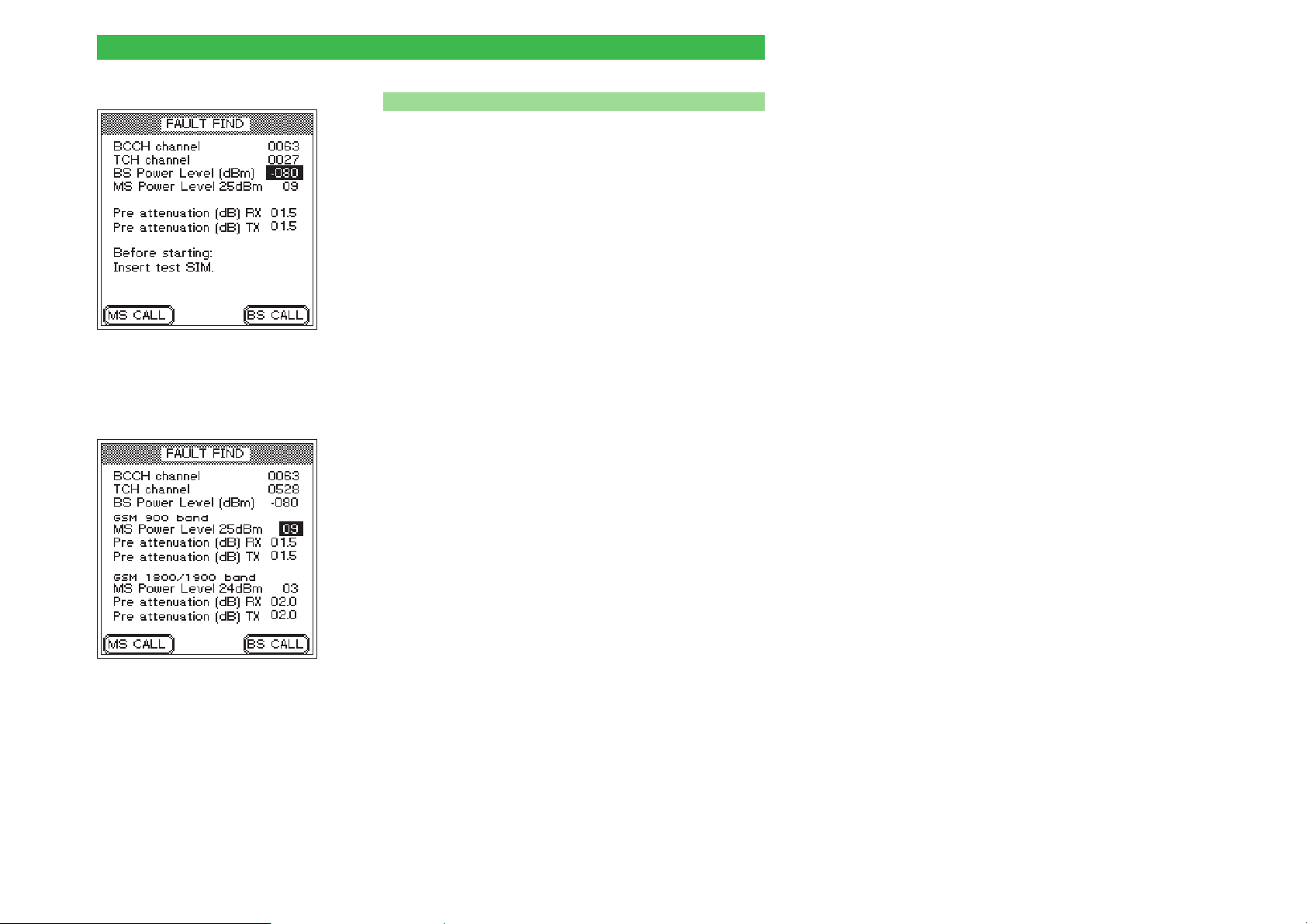
Willtek 4100 FAULT FIND test preparation
Special considerations for dual-band systems
n
When single-band mobile phones are being tested, the
Willtek 4107(S) also displays the FAULT FIND menu in
the form shown on the left. The meanings of the fields
there are described on the following pages.
When dual-band mobile phones are being tested, the
FAULT FIND menu requires the same entries as for
single-band systems, with the exception that certain
entries need to be made twice, once for each band
(see below).
In the descriptions as of this page, the dual-band
+
FAULT FIND menu when testing
single-band mobile phones.
systems will no longer be mentioned separately,
since all the descriptions also apply fully to these
systems.
Separate entry fields for each band
As soon as a dual-band system (GSM 900+1800 or GSM
900+1900) has been set in the Willtek 4107(S), the
FAULT FIND menu assumes the form shown on the
bottom left of this page. The MS Power Level and Pre
attenuation (RX/TX) fields are available separately for
each band. In the case of MS Power Level, this has the
advantage that both transmission branches of the
mobile phone (900 MHz and 1800/1900 MHz) can be
tested independently (for instance one band at power
level 9 and the other at level 3).
FAULT FIND menu when testing
dual-band mobile phones.
The separate entry fields for Pre attenuation,onthe
other hand, benefit the measuring precision. Since
pre-attenuation (and hence the associated
compensation) is frequency-dependent, compensation
values which have been matched to each frequency
band are of benefit. Please refer to pages 3-20 and 4-9
for more details on pre-attenuation and compensation
values.
4-5
Page 65
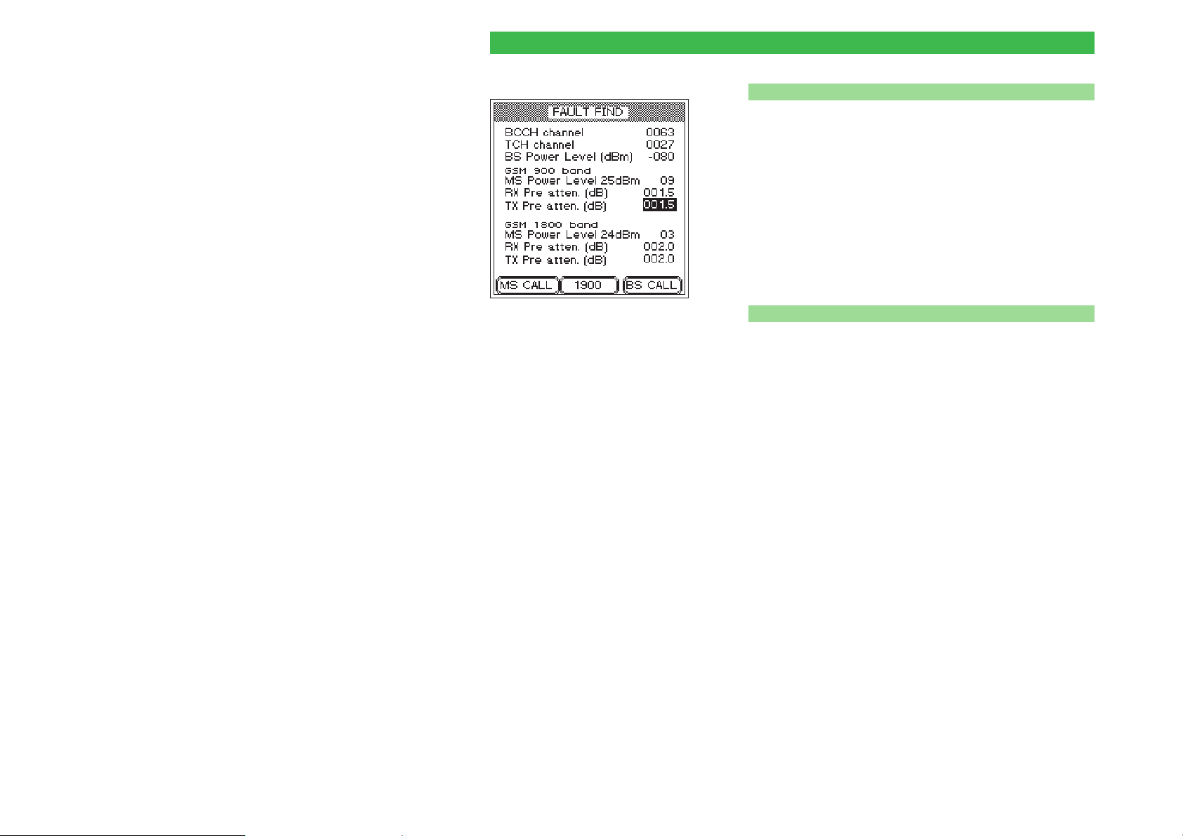
FAULT FIND test preparation Willtek 4100
Special features of multiband systems
n
If when selecting the radio system you have chosen a
multiband system (GSM 900+1800+1900) the
FAULT FIND menu first shows the input fields for the
lower and middle bands. In a similar way to the menu for
the dual-band systems you can first enter the required
values for MS Power Level and Pre atten. (RX,TX) for
each band (see page 4-). Then press {1900} to call the
menu for the upper band and enter the required values
for MS Power Level and Pre atten. (RX,TX). The
{900/1800} softkey takes you back to the input menu for
the lower and middle band.
FAULT FIND menu when testing
multiband mobile phones.
Testing multiband mobile phones
n
It is basically possible to test a multiband mobile phone
on one band after another by simply setting the
appropriate radio system on the tester and testing each
one individually (see page 4-4). However, it is better to
select the appropriate multiband and thus avoid having
to keep going back to the SYSTEM SELECT menu. But
because of the double assignment of channel numbers
in the 1800 and 1900 bands you must bear the
following in mind:
l
It is not possible to change channels between the 900
and 1900 bands or between the 1800 and 1900 bands.
l
If the mobile phone does not switch automatically from
band to band, this must be done manually.
l
To switch the tester from 900/1800 to 1900 you must:
! Terminate the connection.
" Switch band using {900/1800} or {1900}.
§ Allow the mobile phone to register with the new band.
$ Establish a new connection and continue the test.
The following pages will not mention multiband
+
systems explicitly again, since all information
without exception applies to these systems as
well.
4-6
Page 66
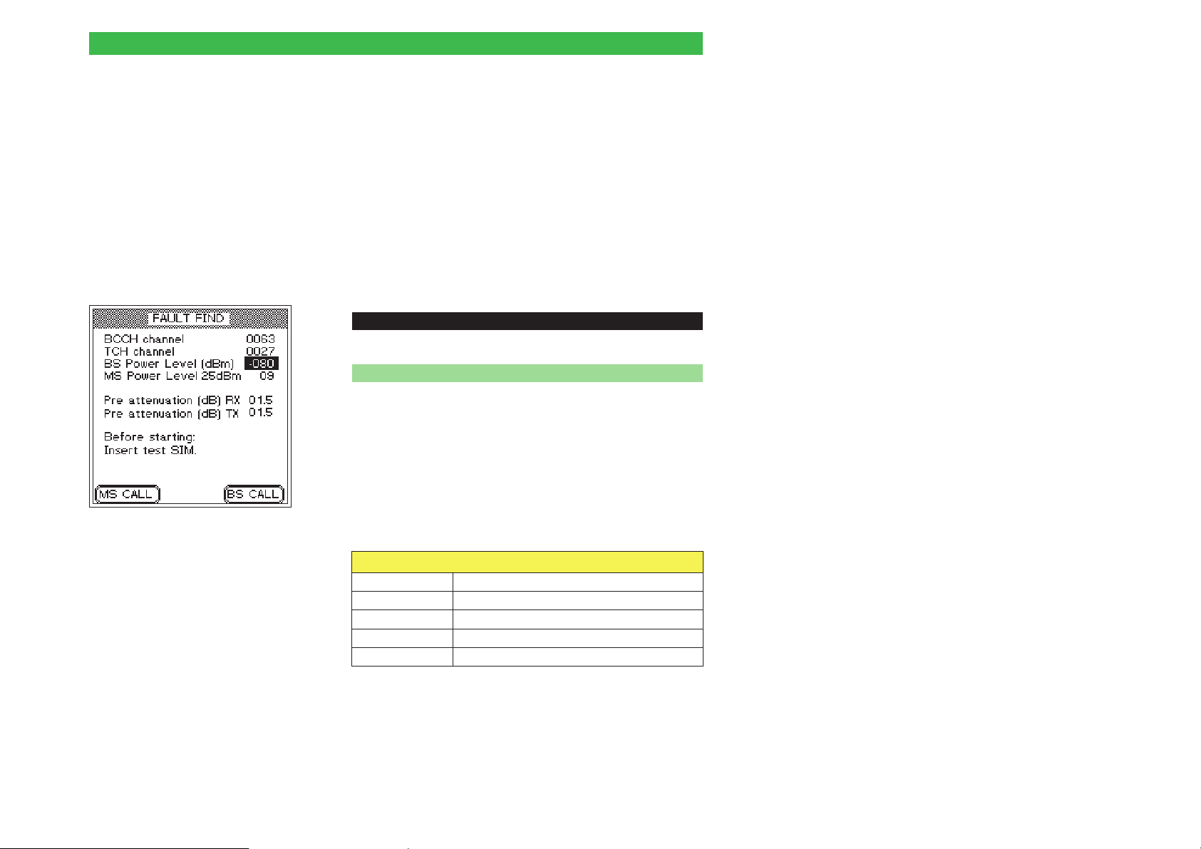
Willtek 4100 FAULT FIND test preparation
BCCH and TCH?
BCCH (Broadcast Control Channel):
This is the channel via which the base
station and the mobile phone exchan
ge fundamental connection data such
as the current location of the mobile
phone and the network ID.
TCH (Traffic Channel): Channel
carrying voice and data traffic.
Invalid input
+
causes the message INPUT
ERROR to be displayed
along with a list of
acceptable values.
Selecting channels/RF power
-
ï
This stage in the test preparation phase applies to any
Willtek 4100. Here you select:
the channel on which signaling between tester and
l
mobile phone is to take place (BCCH)
the channel on which voice traffic between tester and
l
mobile phone is to take place (TCH)
the RF transmit power of the tester (BS Power Level)
l
the RF transmit power of the mobile phone following
l
connection setup (MS Power Level)
Any menu + [FAULT_FIND]
n Entering channel numbers
! Use the cursor keys to select the BCCH channel line.
" Enter the number of the channel which is to be used for
signaling.
§ Press [ENTER] to confirm your input.
$ Use the cursor keys to select the TCH channel line.
% Enter the number of the channel which is to be used for
voice traffic.
& Press [ENTER] to confirm your input.
Permissible channel numbers (BCCH and TCH)
GSM 0001 through 0124
E-GSM 0000 and 0975 through 1023
GSM-R 0955 through 0974
GSM 1800 (PCN) 0512 through 0885 (even numbers only)
GSM 1900 (PCS) 0512 through 0810 (odd numbers only)
4-7
Page 67
FAULT FIND test preparation Willtek 4100
Setting the RF power
n
! Use the cursor keys to select the BS Power Level line.
Invalid input
+
Invalid input causes the
message INPUT ERROR to
be displayed along with a list
of acceptable values.
" Enter a value for the RF transmit power (in dBm) at
which the Willtek 4100 is to send signals to the mobile
phone.
It is best to specify the maximum value to ensure
+
that there are no complications with check-in
attempts. You can always change the power
again to some other value later.
RF transmit power of tester
GSM 900/E-GSM –117 dBm through –45 dBm
GSM 1800 + 1900 –117 dBm through –45 dBm
Observe the specified level range (see chapter 6, Technical data).
The minus sign is added automatically.
§ Press [ENTER] to confirm your input.
$ Use the cursor keys to select the MS Power Level line.
% Enter the power level (corresponding to an RF transmit
power value) at which the mobile phone is to send
signals to the Willtek 4100 (see table below).
On handportables (not car phones) the RF
+
output power is limited to a maximum of 33 dBm.
Bear this in mind when selecting the power level.
& Press [ENTER] to confirm your input.
Permissible power levels and corresponding RF power in dBm
Power level
GSM 900/E-GSM
GSM 1800 (PCN)
GSM 1900 (PCS)
4-8
012345678910111213141516171819 293031
43 41 39 37 35 33 31 29 27 25 23 21 19 17 15 13 11 9 7 5 – – –
302826242220181614121086420–––– 363432
302826242220181614121086420res res res res res 33 32
Page 68
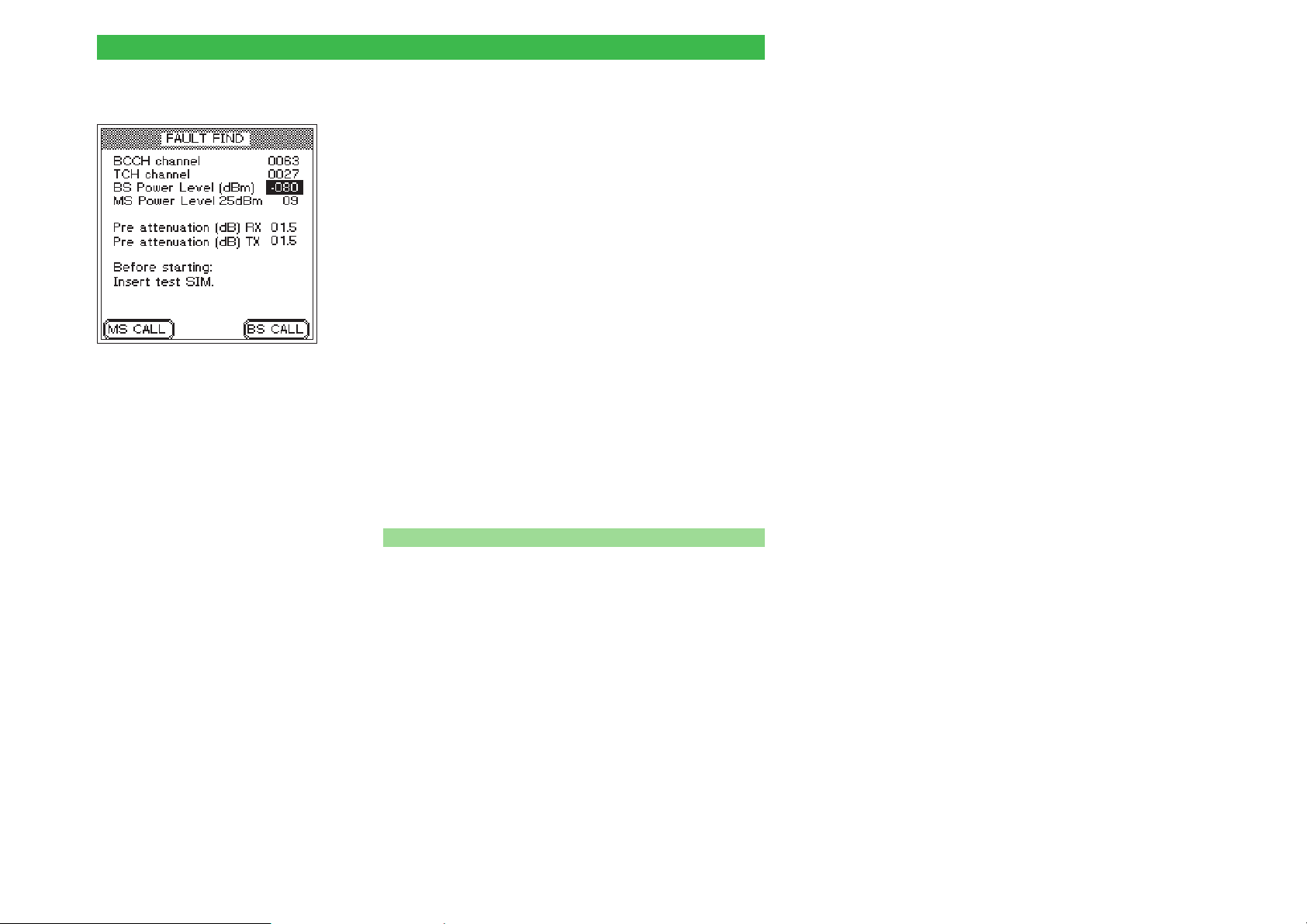
Willtek 4100 FAULT FIND test preparation
Compensating for signal attenuation
You will find details on compensating for signal
attenuation on page 3-23ff. The information given there
for AUTOTESTs also applies to FAULT FIND mode
with the following exceptions:
Only one input field (lines Pre attenuation) is available
l
for each of the compensation values (RX and TX).
The compensation values apply to both the TCH and
l
the BCCH channels (this is valid because no
measurements are performed for the BCCH channel).
FAULT FIND mode provides the option of
+
assigning other channel numbers to the TCH
Each radio system has its own
permitted compensation value
which comes into force
automatically the moment you
select the system.
Any compensation
+
configured in FAULT FIND
mode has no bearing on the
readings in AUTOTEST
mode. Separately defined
compensation values for
individual models of mobile
phones apply in
AUTOTEST mode.
channel after the connection has been
established. For this reason, when evaluating RF
values (e.g. MS Pwr and Rx Level), make sure
that the TCH channel number that is selected, is
the one for which the compensation values
apply. This restriction does not apply for
cable-based connections, which are not
frequency-dependent.
n Compensation values
In the case of a cable-based connection, it is sufficient
to specify a fixed compensation value which you enter
in the RX and TX entry fields.
1.5 for GSM/E-GSM
2.0 for GSM1800 (PCN)/GSM1900 (PCS)
Values are identical for the RX and TX signal paths,
since a cable-based connection is not
frequency-dependent. Please note that these values
only apply if you are using Willtek original accessories
(cable, RF adapter). If this is not the case, or if you are
using a wireless connection, other compensation
values apply, which have to be determined on an
individual basis.
4-9
Page 69

FAULT FIND test preparation Willtek 4100
Installing the test SIM
See page 2-14 for installation instructions.
It is not absolutely necessary to insert the test SIM for
FAULT FIND mode. Apart from the bit/frame error rate
measurements, all tests can also be carried out with
the original SIM. There is, however, one important
reason for installing the test SIM. With the test SIM
installed, the mobile phone forgets all its information
about its usual home network and instead considers
the GSM network simulated by the tester to be its home
network. The advantage of this is that as a rule no
problems will be encountered when registering the
mobile phone into the test network (see also
page 4-13).
Switch the SIMs back over again once testing of
+
the mobile phone has finished!
Connecting the mobile phone
4-10
For notes on connection, see page 2-16.
The correct connection type depends on the tests and
measurements you want to perform. Cable-based
connection provides the greatest testing depth, but
requires suitable RF adapters.
Please note that connections using the Universal
+
Antenna Coupler and in particular antenna
connections result in RF measurements which
are subject to a degree of uncertainty. The table
on page 3-17 provides information on the tests
and measurements which are affected.
Page 70
Willtek 4100 FAULT FIND test preparation
This is what is tested
In FAULT FIND mode you can test the following
functions and quality-determining parameters of a
mobile phone:
Function
Registration
Outgoing call from mobile phone (connection setup)
Incoming call (mobile phone)
Response to TCH change
Response to RF power change (tester)
Response to power level change (mobile phone)
Hang-up on mobile phone
Hang-up on tester
Correct transmission of IMEI/IMSI
Correct interpretation of power class
Mobile phone keypad
Acoustic speech test (audio loopback)
Broadcast cell (display text messages)
Parameters
Mobile phone transmit power
Phase error (RMS and peak)
Frequency error
RX level
RX quality
Power-time template
Bit/frame error rate
Test 1.0
Test 2.0
Test 3.0
Test 4.1
Test 4.2
Test 4.3
Test 4.4
Test 4.5
Test 6.0
Test 6.0
Test 2.0
Test 7.0
Test 8.0
Test 4.0
Test 4.0
Test 4.0
Test 4.0
Test 4.0
Test 4.0
Test 5.0
4-11
Page 71
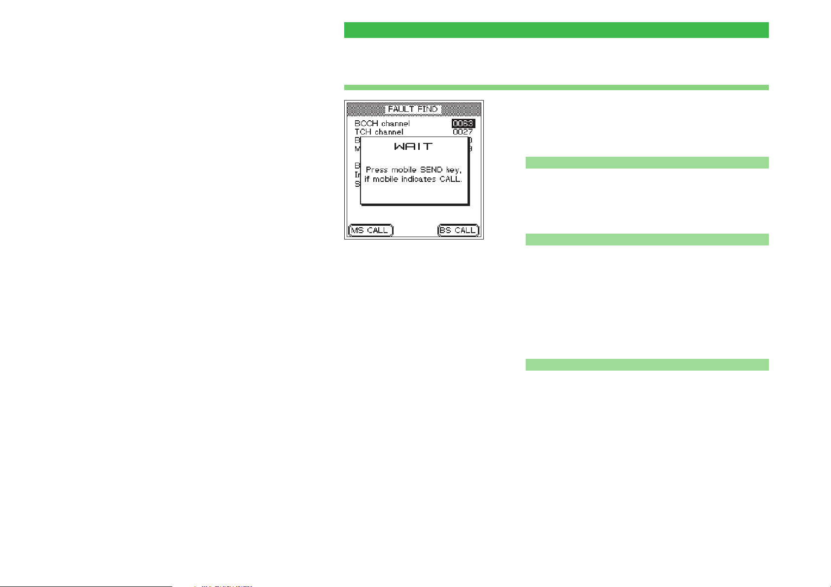
Test 1.0: Network identification and registration Willtek 4100
Test 1.0: Network identification and registration
Registering the mobile phone on the GSM radio
network simulated by the Willtek 4100 is a fundamental
test. If this initial test fails, there is something seriously
wrong, and none of the other tests can be performed.
Preconditions for testing
n
Test preparation completed (see page 4-4) and
l
Willtek 4100 ready for use (FAULT FIND menu on
display)?
Mobile phone switched off? If it is on, switch it off now.
l
n Test 1.0 step by step
Tester display after {BS_CALL} has
been pressed.
Selecting the test network
Depending on the type of mobile
phone and how it is configured,
widely differing actions are required
to select the network. It may be
that you first have to call functions
like "Network selection" and "New
search" manually. However you go
about it, once the network has
been found, the mobile must
display the ID of the test network,
which is as follows:
MCC:001 MNC:01
The mobile phone may show the ID
in a slightly different format (e.g.
1 1 or 00101). The important point
is that you do not make the mistake
of selecting a public network.
! Switch the mobile phone on and (if asked to) enter the
PIN (PIN of test SIM = 0000).
" It may now be necessary to select the test network, but
only on a mobile phone with its original SIM (see the
text on the left).
§ Press the {BS_CALL} softkey on the Willtek 4100 (the
tester calls the mobile phone and displays a WAIT
menu) and observe how the mobile phone responds.
n
Test 1.0 result
The mobile phone reports the incoming call visually or
J
audibly. It can only do so if it has correctly identified the
test network and registered. Now go on to Test 3.0,
step 2, or press [ESCAPE] to go back to the
FAULT FIND menu.
There is no visual or audible calling signal. This should
L
not be treated as a fault until all the solutions described
in the next section have failed to result in registration.
After each failed registration attempt, press [ESCAPE]
to return to the FAULT FIND menu.
4-12
Page 72

Willtek 4100 Test 1.0: Network identification and registration
Problems with registration
Even with an intact mobile phone, there is one problem
which may arise – with an original SIM – when you
attempt to register onto the test network:
Location update?
When you switch on a mobile phone
which is fitted with its original SIM, it
immediately searches for receivable
GSM base stations. Every base
station identifies itself with a typical
LAC (Location Area Code).
The LAC of the last base station
used is stored on the SIM. If the
phone again detects the last station it
used (by comparing the LACs), it
registers automatically. If this is not
possible, e.g. after a change of
location, a location update is
performed. Here the mobile phone
checks which base station on the
home network it can receive best
(home network: the GSM network
that was activated on the SIM when
the phone was purchased).
The phone stores the LAC of this
base station on the SIM and at the
same time registers into the home
network. The phone acts in the same
way if the test SIM is mounted,
except that in this case the home
network is held to be the GSM radio
network simulated by the tester.
The mobile phone checks into a public network instead
l
of the test network. This is typically likely to happen
under the following conditions:
wireless connection between test unit and tester
–
signal from Willtek 4100 competing with strong base
–
stations.
Problem solving
Take the following steps and repeat them after each
registration attempt (Test 1.0).
! Check that the RF output level of the tester is set to the
maximum value.
" If the check-in attempt fails with the original SIM, switch
off the mobile phone and install the test SIM (see also
page 2-14).
§ If the attempt fails with wireless connection, try again
using the cable-based connection via the RF adapter.
4-13
Page 73
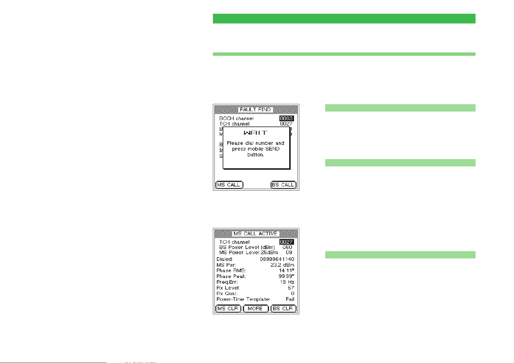
Test 2.0: MS CALL connection setup Willtek 4100
Test 2.0: MS CALL connection setup
Test 2.0 checks whether the mobile phone is able to
set up a telephone connection to the Willtek 4100.
Once the connection has been established, many other
functions and parameters of the mobile phone can be
checked.
Preconditions for testing
n
The phone has previously passed Test 1.0 and
l
identified the radio network simulated by the tester.
There is no existing telephone connection between the
l
phone and the tester (if there is one, release it using
Test 4.4 or 4.5).
n Test 2.0 step by step
! Press the {MS_CALL} softkey on the Willtek 4100 (the
tester waits for a call from the mobile phone and
displays a WAIT menu). The display shows a prompt
for action (see picture).
" Enter any number (up to 20 digits) on the mobile
phone. Include all the numbers from 0 through 9 so that
you can read these later on the tester's display and
identify any defective number keys.
§ On the mobile phone, press the key with the "Send"
function to initiate connection setup.
4-14
n
Test 2.0 result
Connection setup was successful; the tester's display
J
now shows the MS CALL ACTIVE menu (in
subsequent tests, MS reminds you that connection
setup was initiated by MS CALL). Go on to Test 4.0.
Connection setup has failed; the tester's display
L
continues to show the WAIT menu. The mobile phone
failed the test. Press [ESCAPE] to return to the
FAULT FIND menu.
Page 74
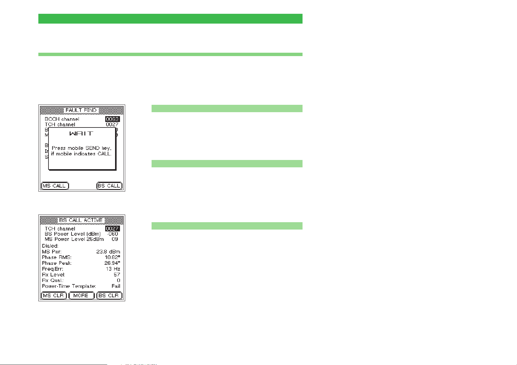
Willtek 4100 Test 3.0: BS CALL connection setup
Test 3.0: BS CALL connection setup
Test 3.0 checks whether the mobile phone is able to
handle an incoming connection request from the
Willtek 4100. Once the connection has been
established, many other functions and parameters of
the mobile phone can be checked.
Preconditions for testing
n
The phone has previously passed Test 1.0 and
l
identified the radio network simulated by the tester.
There is no existing telephone connection between the
l
phone and the tester (if there is one, release it using
Test 4.4 or 4.5).
n Test 3.0 step by step
! Press the {BS_CALL} softkey on the Willtek 4100 (the
tester call the mobile phone and displays a WAIT
menu).
" In response to a visual and/or audible calling signal on
the mobile phone, press the "Send" on the mobile
phone to answer the call.
n
Test 3.0 result
Connection setup was successful; the tester's display
J
now shows the BS CALL ACTIVE menu (in subsequent
tests, BS reminds you that connection setup was
initiated by BS CALL). Go on to Test 4.0.
Connection setup has failed; the tester's display
L
continues to show the WAIT menu. The mobile phone
failed the test. Press [ESCAPE] to return to the
FAULT FIND menu.
4-15
Page 75
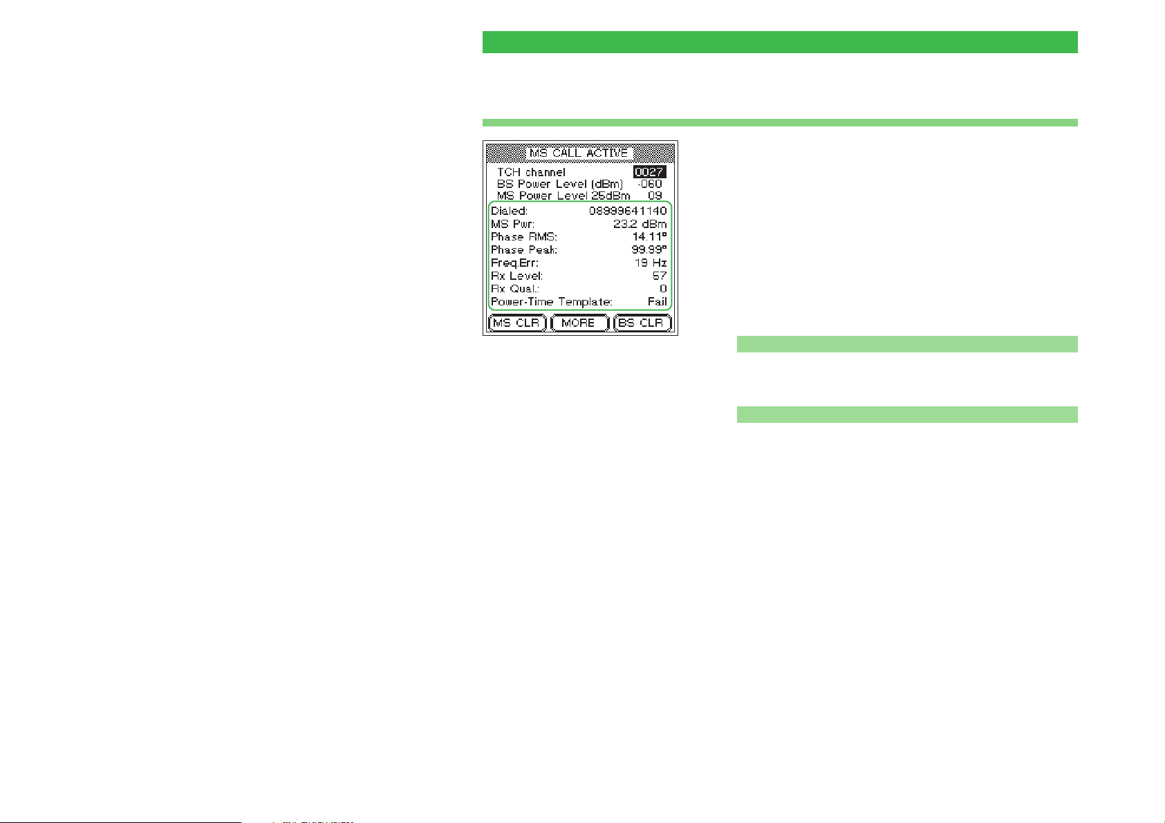
Test 4.0: Messages and measurements Willtek 4100
Test 4.0: Messages and measurements
On successful connection setup the display shows
messages and quality-determining measurements
directly on the CALL ACTIVE menu. The indications
always apply to the test conditions described in the first
three lines of the menu. The effect of modifying test
conditions (see Tests 4.1 through 4.3) can be seen
immediately.
Please note that any RF level measurements are
+
only correct if the signal attenuation has been
correctly compensated (see also page 4-9).
n Preconditions for testing
There must be a valid telephone connection between the
Precision measurements
Always take into account the
measuring tolerances of the tester
(see chapter 6, Technical data)
when evaluating any of the
measurements.
l
mobile phone and the tester, set up in Test 2.0 or 3.0.
n Test 4.0, interpreting the indications
Dialed Number dialed on the mobile phone in the course of
Test 2.0 (MS CALL) (nothing is shown if the connection
was set up with BS CALL).
4-16
The value is the same as the number that was dialed.
J
If the value is different (digits missing or the same digit
L
repeated several times in succession), there is
something wrong with the numeric keypad (oxidized
contacts, key bounce).
MS Pwr RF transmit power of the mobile phone.
The value matches the currently applicable power level
J
of the mobile phone (target value shown on the
MS Power Level line). Allowable deviations from the
target value are indicated in the table (as per GSM
standard).
Page 76
Willtek 4100 Test 4.0: Messages and measurements
The value is outside the permitted tolerances. This can
L
lead to connection breakdown (value too low) or to
interference with other subscribers (value too high). In
the event of connection breakdown, press and hold
down {BS_CLR} until you hear the acknowledgment
signal (this takes you back to the FAULT FIND menu).
Example
The tester reports a value of
23.2 dBm for MS Pwr. The
MS Power Level line shows you
the target value (here 25 dBm)
and the associated power level
(09). According to the table, on
power level 9 the test unit is
allowed to transmit at 25 dBm
±3 dB. That means that the
measured value is within the
permitted tolerances.
Power level/RF power/permissible tolerances
GSM/E-GSM GSM 1800 (PCN) GSM 1900 (PCS)
0 43 dBm ±2dB 29 36dBm ±2dB 29
1 41 dBm ±3dB 30 34dBm ±3dB 30 33dBm ±2dB
2 39 dBm ±3dB 31 32dBm ±3dB 31 32dBm ±3dB
3 37 dBm ±3dB 0 30 dBm ±3dB 0 30 dBm ±3dB
4 35 dBm ±3 dB 1 28 dBm ±3 dB 1 28 dBm ±3dB
5 33 dBm ±3 dB 2 26 dBm ±3 dB 2 26 dBm ±3dB
6 31 dBm ±3dB 3 24 dBm ±3dB 3 24 dBm ±3dB
7 29 dBm ±3 dB 4 22 dBm ±3 dB 4 22 dBm ±3dB
8 27 dBm ±3 dB 5 20 dBm ±3 dB 5 20 dBm ±3dB
9 25 dBm ±3 dB 6 18 dBm ±3 dB 6 18 dBm ±3dB
10 23 dBm ±3 dB 7 16 dBm ±3 dB 7 16 dBm ±3dB
11 21 dBm ±3 dB 8 14 dBm ±3 dB 8 14 dBm ±3dB
12 19 dBm ±3 dB 9 12 dBm ±4 dB 9 12 dBm ±4dB
13 17 dBm ±3dB 10 10dBm ±4dB 10 10dBm ±4dB
14 15 dBm ±3 dB 11 8 dBm ±4 dB 11 8 dBm ±4dB
15 13 dBm ±3 dB 12 6 dBm ±4 dB 12 6 dBm ±4dB
16 11 dBm ±5 dB 13 4 dBm ±4 dB 13 4 dBm ±4dB
17 9 dBm ±5 dB 14 2 dBm ±5 dB 14 2 dBm ±5dB
18 7 dBm ±5 dB 15 0 dBm ±5 dB 15 0 dBm ±5dB
19 5 dBm ±5dB
Highlighted values: When the power level
+
–– ––– –
res. –
corresponds to the power class of the mobile
phone, then the tolerances shall be ±2.0 dB.
4-17
Page 77
Test 4.0: Messages and measurements Willtek 4100
Phase RMS, Peak Phase error in GSM burst signal (RMS value left, peak
value right). The phase error is a quality indicator for
correct adjustment of the modulator.
The phase error is not outside the following limits (GSM
J
standard, irrespective of radio system):
RMS: £ 5°
Peak: £ 20°
The value is over the limits. Typical symptoms:
L
problems with connection setup, problems with
maintaining a connection, distortion of the voice signal.
Freq. Err Frequency error of mobile phone RF carrier signal
compared to target value.
Permitted frequency error (GSM standard)
GSM/E-GSM GSM 1800 (PCN) GSM 1900 (PCS)
£±90 Hz £±180 Hz £±180 Hz
Frequency error is within limits.
J
Excessive frequency error may lead to interference with
L
other subscribers on adjacent channels or exhibit the
same symptoms as an unacceptable phase error.
RX Level Measure of the RF level at which the mobile phone
receives the signal from the base station (here the
tester). Mobile phones measure the RF receive level at
regular intervals and report the measurement to the
base station in the form of a code number (0 through
63). The higher the RF level measured, the higher the
code number.
4-18
It is advisable to check the Rx Level code number for a
variety of BS Power Level settings (high, medium and
low value).
Page 78
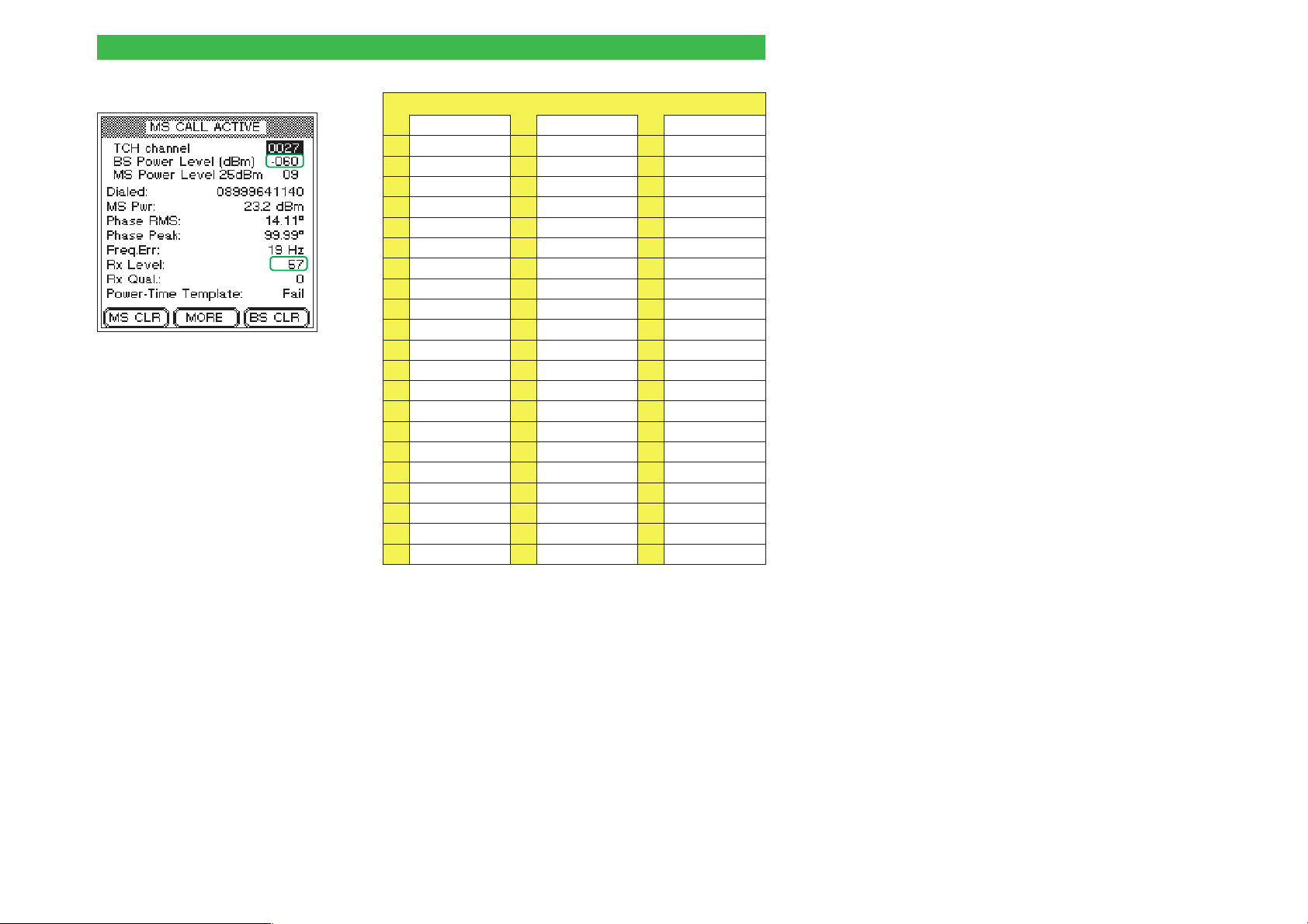
Willtek 4100 Test 4.0: Messages and measurements
Equivalent code numbers/RF receive levels (dBm)
0 < –110 22 –89 to –88 44 –67 to –66
1 –110 to –109 23 –88 to –87 45 –66 to –65
2 –109 to –108 24 –87 to –86 46 –65 to –64
3 –108 to –107 25 –86 to –85 47 –64 to –63
4 –107 to –106 26 –85 to –84 48 –63 to –62
5 –106 to –105 27 –84 to –83 49 –62 to –61
6 –105 to –104 28 –83 to –82 50 –61 to –60
7 –104 to –103 29 –82 to –81 51 –60 to –59
8 –103 to –102 30 –81 to –80 52 –59 to –58
9 –102 to –101 31 –80 to –79 53 –58 to –57
10 –101 to –100 32 –79 to –78 54 –57 to –56
The reported Rx level must match
the BS power level.
11 –100 to –99 33 –78 to –77 55 –56 to –55
12 –99 to –98 34 –77 to –76 56 –55 to –54
13 –98 to –97 35 –76 to –75 57 –54 to –53
14 –97 to –96 36 –75 to –74 58 –53 to –52
15 –96 to –95 37 –74 to –73 59 –52 to –51
16 –95 to –94 38 –73 to –72 60 –51 to –50
17 –94 to –93 39 –72 to –71 61 –50 to –49
18 –93 to –92 40 –71 to –70 62 –49 to –48
19 –92 to –91 41 –70 to –69 63 > –48
20 –91 to –90 42 –69 to –68
21 –90 to –89 43 –68 to –67
––
––
Under the GSM standard, the code number shown in
J
the Rx Level field should match the RF output level set
on the tester (value on BS Power Level line – see table
for conversion).
The RF receive level derived from the Rx Level code
L
number deviates by an unacceptable amount from the
target value (BS Power Level).
4-19
Page 79
Test 4.0: Messages and measurements Willtek 4100
Rx Qual Measure of transmission quality at the current RF
receive level. Mobile phones check the bit error rate
(BER) of the decoded data at regular intervals and
report the measurement to the base station in the form
of a code digit (0 through 7). The higher the BER, the
higher the code digit.
Equivalent code digits/BERs*
< 0.2 %
0
0.4 % to 0.8 %
2
1.6 % to 3.2 %
4
6.4 % to 12.8 %
6
*) BER measured by the mobile phone. Not to be confused
with the tester's BER measurement.
At an RF receive level of –102 dBm the BER reported
J
0.2 % to 0.4 %
1
0.8 % to 1.6 %
3
3.2 % to 6.4 %
5
> 12.8 %
7
by the mobile phone must be < 2.44 % (equivalent
code digit: 4).
The BER is over the permitted limit. (The greater the
L
overshoot, the greater the resulting distortion of the
voice signal. For acoustic confimation run Test 7.0.)
4-20
Page 80
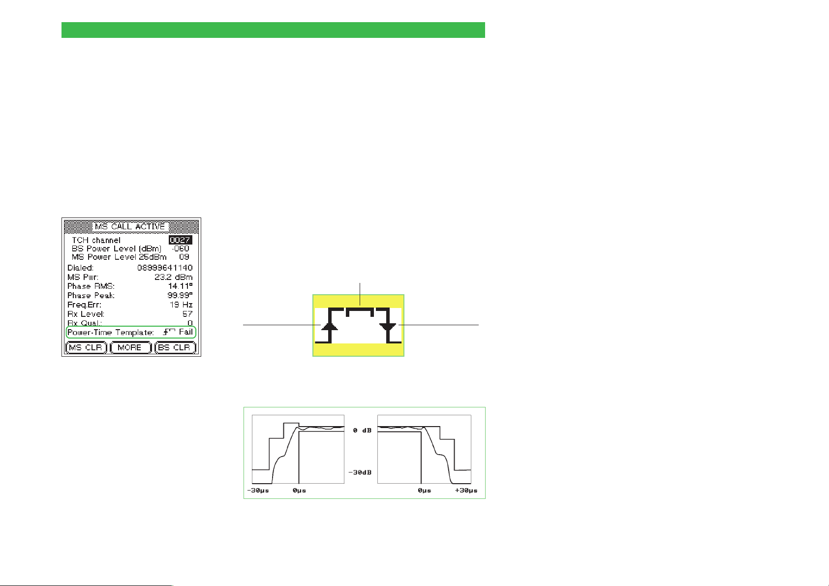
Willtek 4100 Test 4.0: Messages and measurements
Power-Time Template Under the GSM standard, the profile of the GSM burst
signal over time must fit into a "template" which
allocates defined tolerances zones to the signal
pattern. A Willtek 4100 checks that the burst does not
overshoot the tolerance limits at any point in the
template and reports the result as Pass or Fail.
Pass The burst profile is acceptable.
Fail The burst goes outside the tolerance limits at one or
more points. Typical symptom: interference with calls
running on the same RF channel but in different
timeslots.
Willtek 4107S only: Three symbols indicate the
locations where the tolerance zones were exceeded.
These symbols (the Burst Edge Failure Indication) can
appear on their own or in combination with the other
symbols.
Error in horizontal section of burst waveform
Willtek 4107S only: Symbols
indicate the locations where the
tolerance zones were exceeded.
Error on
rising burst
edge
Error on
falling burst
edge
The following diagram illustrates the zones of the
power-time template.
4-21
Page 81
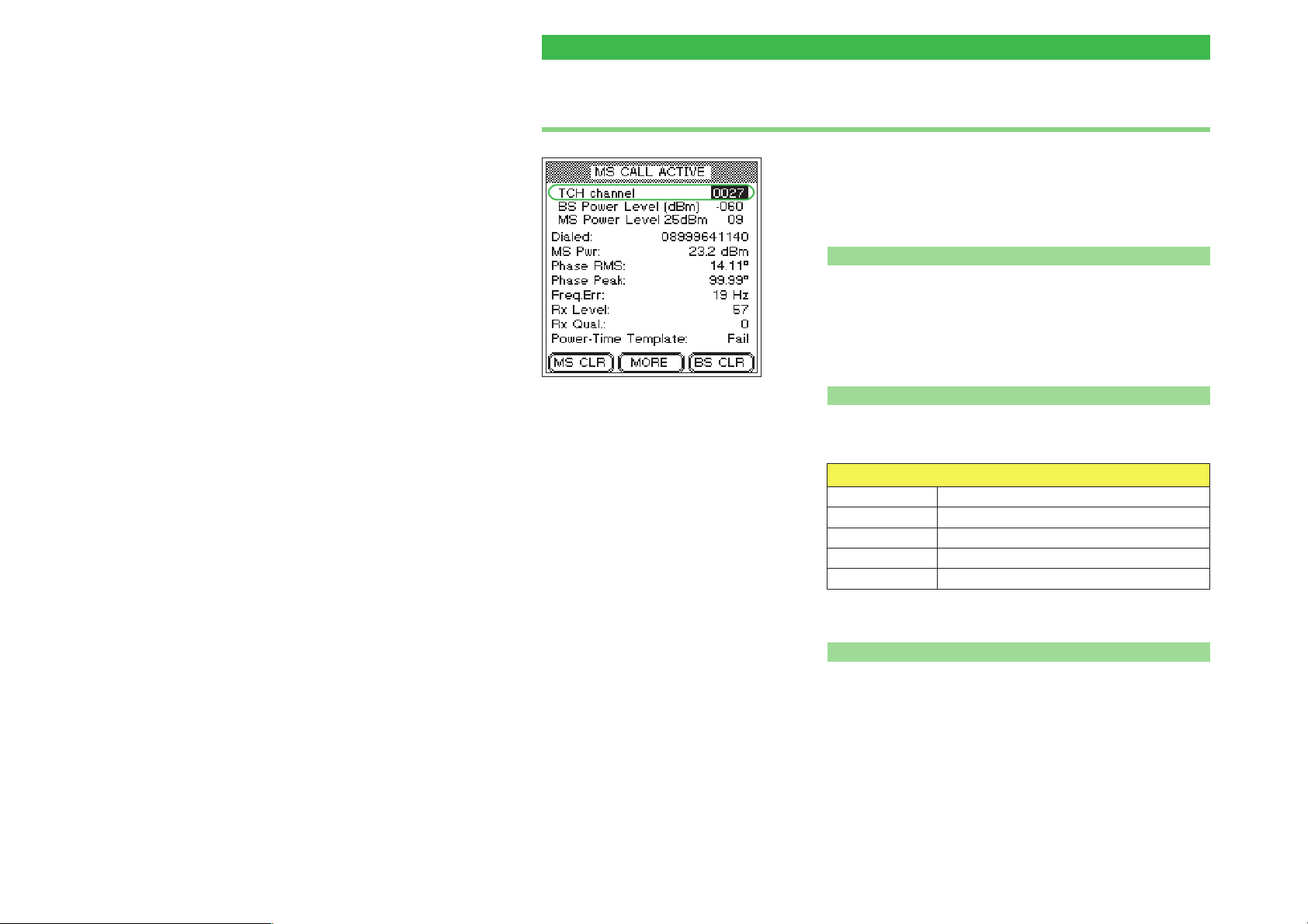
Test 4.0: Messages and measurements Willtek 4100
Test 4.1: Changing the voice channel
While a telephone connection is in place, a mobile
phone must be able to switch to another voice channel
(TCH) allocated by the base station (in our case the
Willtek 4100).
Preconditions for testing
n
There must be a valid telephone connection between the
l
mobile phone and the tester, set up in Test 2.0 or 3.0.
The BS CALL ACTIVE or MS CALL ACTIVE menu
l
must be visible (to get back to this menu from
lower-level menus press [ESCAPE]).
n Test 4.1 step by step
Multiband mobile phones:
It is not possible to switch talk
channels directly between the
900/1800 and 1900 bands. The
reason for this is that the channel
numbes are assigned twice (see
also pae 4-6).
! Use the cursor keys to select the TCH channel line.
" Enter another valid channel number:
Permissible channel numbers (BCCH and TCH)
GSM 0001 through 0124
E-GSM 0000 and 0975 through 1023
GSM-R 0955 through 0974
GSM 1800 (PCN) 0512 through 0885 (even numbers only)
GSM 1900 (PCS) 0512 through 0810 (odd numbers only)
4-22
§ Press [ENTER] to confirm your input.
n
Test 4.1 result
The connection is maintained, the CALL ACTIVE menu
J
continues to show acceptable measurements. Repeat the
test with a different channel number or run the next test.
The connection breaks down. The tester's display stops
L
showing measurements. The mobile phone has failed
the test. Press and hold down {BS_CLR} until you hear
the acknowledgment signal (back to the FAULT FIND
menu).
Page 82
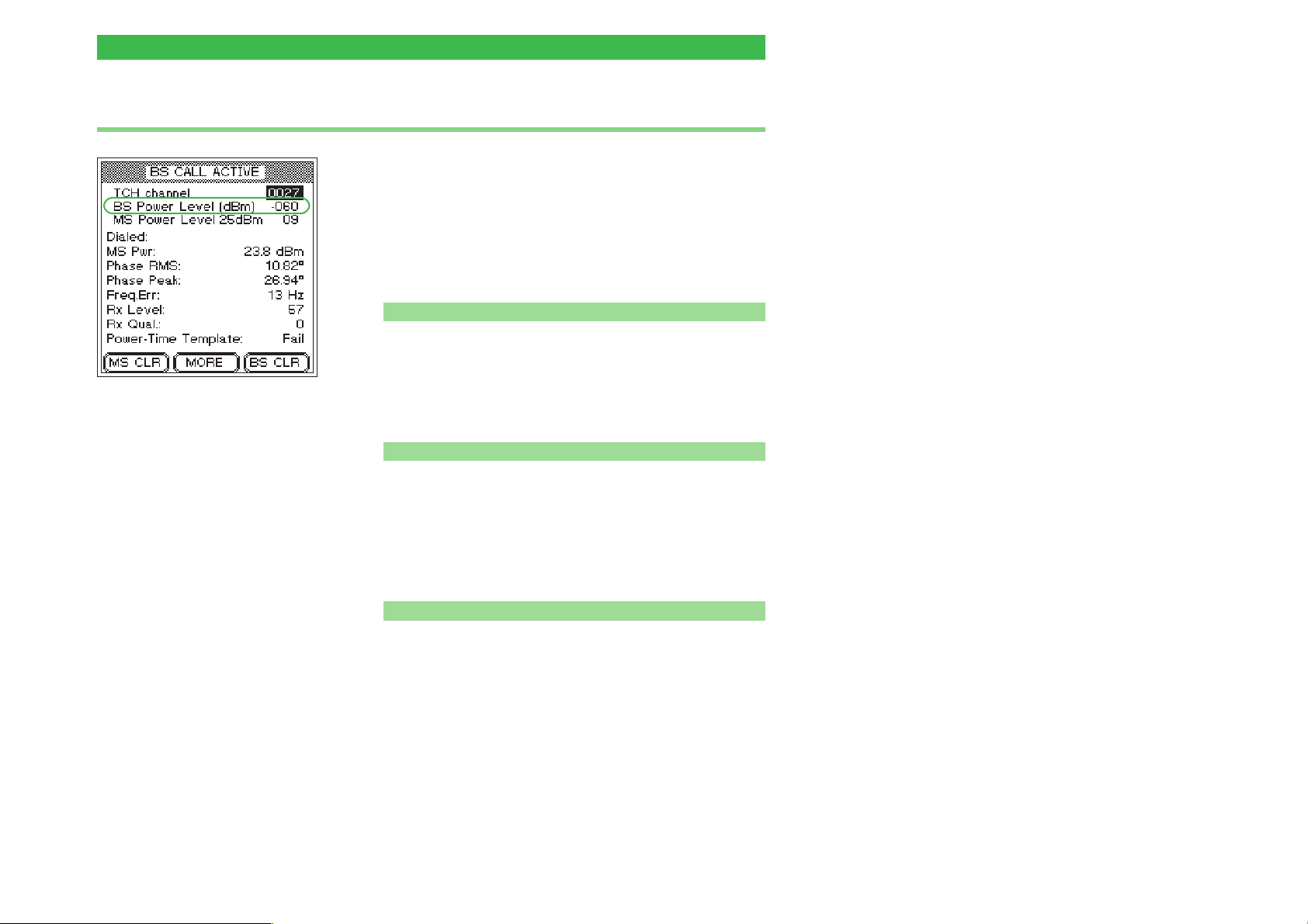
Willtek 4100 Test 4.0: Messages and measurements
Test 4.2: Reducing the RF power (from the tester)
This test simulates harsh reality: the farther you are
from the base station, the lower the RF received level
by your mobile phone. As required by the GSM
specification, a mobile phone should be able to
maintain a connection without malfunctioning at a
receive level at least as low as about –102 dBm
(portables) or –104 dBm (car phones).
Preconditions for testing
n
There must be a valid telephone connection between the
l
mobile phone and the tester, set up in Test 2.0 or 3.0.
The BS CALL ACTIVE or MS CALL ACTIVE menu
l
must be visible (to get back to this menu from
lower-level menus press [ESCAPE]).
n Test 4.2 step by step
! Use the cursor keys to select the BS Power Level line.
" Enter the tester's RF transmit level. According to the
GSM standard this should be:
–102 dBm for handportables
–104 dBm for car phones
§ Press [ENTER] to confirm your input.
n
Test 4.2 result
The connection is maintained, the CALL ACTIVE menu
J
continues to show acceptable measurements. Repeat
the test with a lower RF level or run the next test.
The connection breaks down. The tester's display stops
L
showing measurements. The RF sensitivity of the
mobile phone is insufficient. Press and hold down
{BS_CLR} until you hear the acknowledgment signal
(back to the FAULT FIND menu). Restart the test (at a
higher level, e.g. –90 dBm) and gradually determine the
exact value of the RF level at which the connection
breaks down.
4-23
Page 83
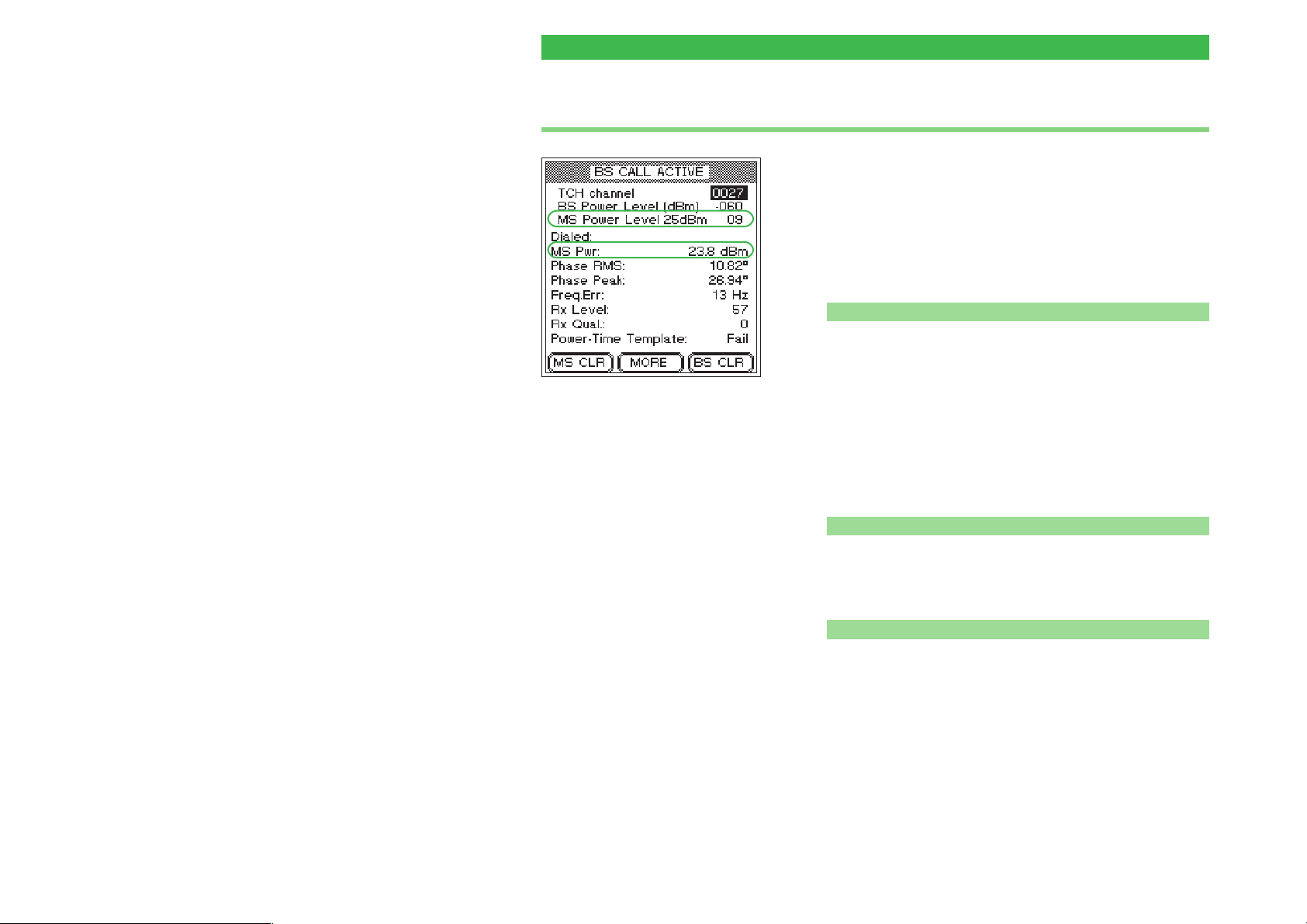
Test 4.0: Messages and measurements Willtek 4100
Test 4.3: Changing power levels
While a telephone connection is in place, a mobile
phone must be able to switch to another power level
allocated to it by the base station (in our case the
tester). This helps save battery power when
approaching a base station and ensure that the
connection is maintained when moving away from a
base station.
Preconditions for testing
n
There must be a valid telephone connection between the
l
mobile phone and the tester, set up in Test 2.0 or 3.0.
The BS CALL ACTIVE or MS CALL ACTIVE menu
l
Changes in the MS power level
should have an immediate impact
on the MS Pwr measurement.
must be visible (to get back to this menu from
lower-level menus press [ESCAPE]).
This test will only have correct and precise
+
results when the tester and the mobile phone are
connected by cable.
4-24
n Test 4.3 step by step
! Use the cursor keys to select the MS Power Level line.
" Enter a different power level.
§ Press [ENTER] to confirm your input.
n
Test 4.3 result
The connection is maintained, the MS Pwr measure
J
ment matches the selected power level on the
MS Power Level line. Repeat the test with other power
levels or run the next test.
The connection breaks down or the MS Pwr measure
L
ment is outside the permitted tolerances (see the table on
page 4-17). Press and hold down {BS_CLR} until you hear
the acknowledgment signal (back to the FAULT FIND
menu). The mobile phone has failed the test.
-
-
Page 84
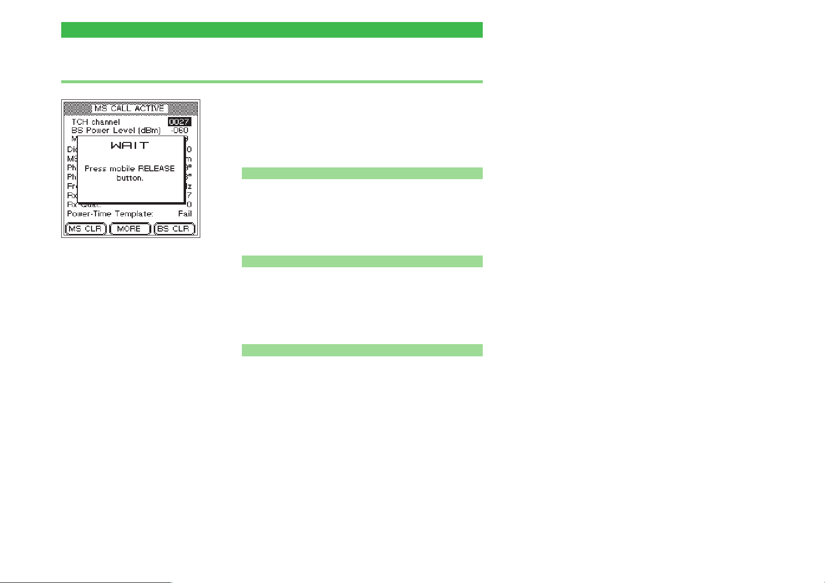
Willtek 4100 Test 4.0: Messages and measurements
Test 4.4: Clear down on the mobile phone
A telephone connection can be released by either
party, either from the mobile phone or from the base
station. This test determines whether the connection is
released correctly if release is initiated from the mobile
phone.
Preconditions for testing
n
There must be a valid telephone connection between the
l
mobile phone and the tester, set up in Test 2.0 or 3.0.
The BS CALL ACTIVE or MS CALL ACTIVE menu
l
must be visible (to get back to this menu from
lower-level menus press [ESCAPE]).
{MS_CLR} makes the tester prompt
you to press the "Release" button
on the mobile phone.
If this is the last test on the
+
phone and you have
installed the test SIM,
please do not forget to
remove the test SIM once
the test is over!
n Test 4.4 step by step
! Press the {MS_CLR} softkey. If this softkey is not shown:
press {MORE}.
" Press the key which has the "Release" function on the
mobile.
§ Observe the tester's display.
n
Test 4.4 result
Following correct connection release, the Willtek 4100
J
shows the FAULT FIND menu again. You can now start
setting up a new connection with {MS_CALL} or
{BS_CALL} or go back to the SYSTEM SELECT menu
by pressing [ESCAPE].
Error releasing connection, e.g. because the "Release"
L
key on the mobile phone is defective. Press and hold
down {BS_CLR} until you hear the acknowledgment
signal (back to the FAULT FIND menu), or switch the
device off for a short while. The mobile phone has
failed the test.
4-25
Page 85
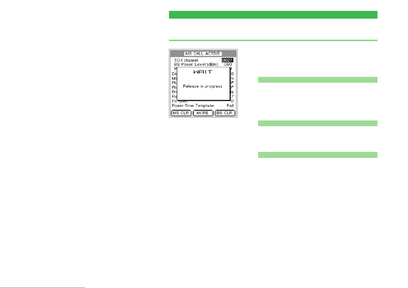
Test 4.0: Messages and measurements Willtek 4100
Test 4.5: Clear down on the tester
A telephone connection can be released by either
party, either from the mobile phone or from the base
station. This test determines whether the connection is
released correctly if release is initiated from the tester.
Preconditions for testing
n
There must be a valid telephone connection between the
l
mobile phone and the tester, set up in Test 2.0 or 3.0.
The BS CALL ACTIVE or MS CALL ACTIVE menu
l
must be visible (to get back to this menu from
lower-level menus press [ESCAPE]).
If connection cleardown with
{BS_CLR} is completed correctly, the
display shows the WAIT
information box for only about 4 s.
If this is the last test on the
+
phone and you have
installed the test SIM,
please do not forget to
remove the test SIM once
the test is over!
n Test 4.5 step by step
! Press the {BS_CLR} softkey. If this softkey is not shown:
press {MORE}.
" Observe the tester's display.
n Test 4.5 result
Following correct connection release (duration: max.
J
about 5 seconds), the Willtek 4100 shows the
FAULT FIND menu again. You can now start setting up
a new connection with {MS_CALL} or {BS_CALL} or go
back to the SYSTEM SELECT menu by pressing
[ESCAPE].
Error releasing connection. If the tester is still showing
L
the WAIT menu after about 20 seconds, switch the
device off for a short while. The mobile phone has
failed the test.
4-26
Page 86
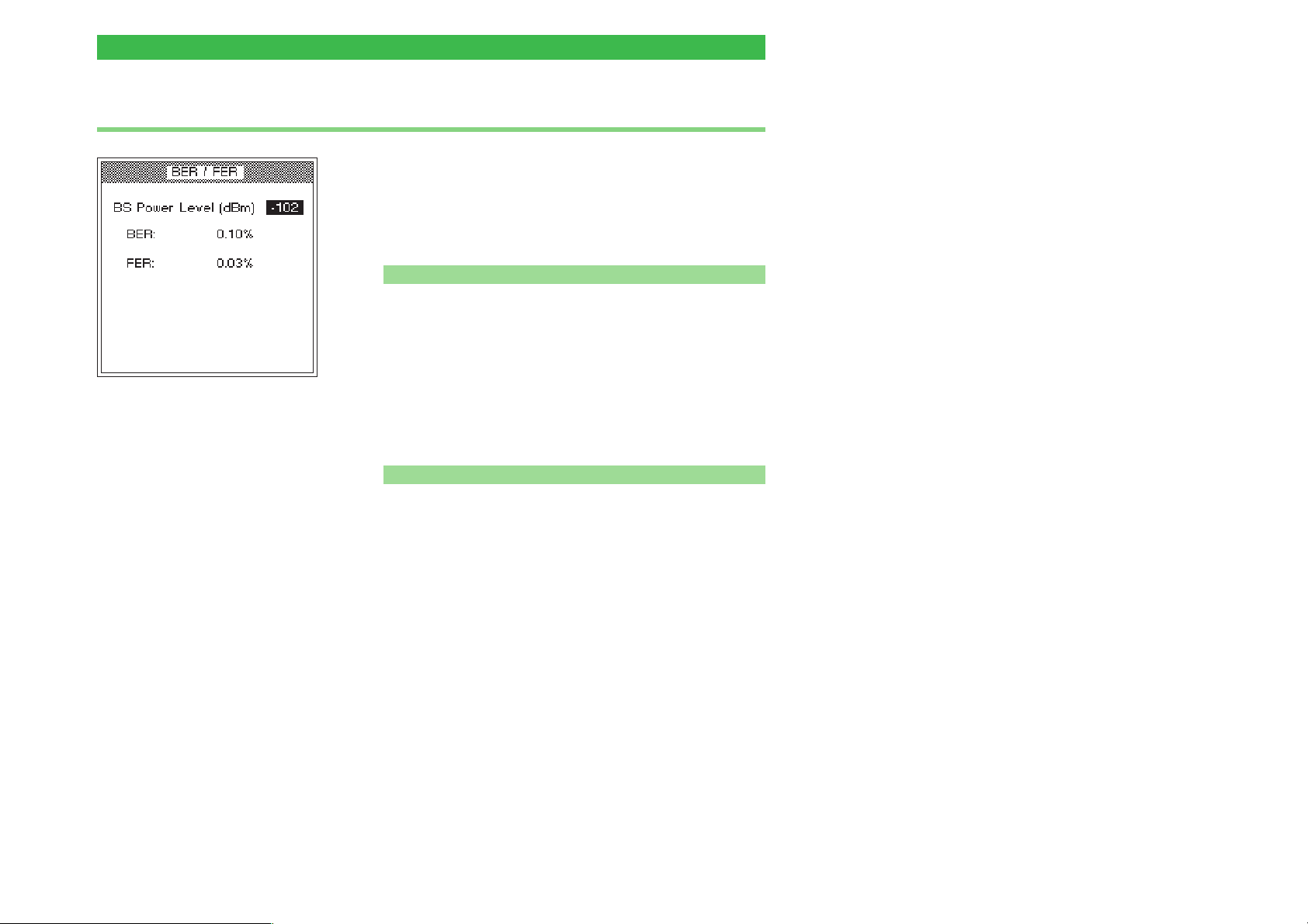
Willtek 4100 Test 4.0: Messages and measurements
Test 5.0: Measuring the bit and frame error rate
The bit and frame error rate is a measure of the RF
sensitivity of a mobile phone. Even at a low RF receive
level, mobile phones should continue to offer
acceptable voice transmission quality (low BER/FER
values).
Preconditions for testing
n
There must be a valid telephone connection between the
l
mobile phone and the tester, set up in Test 2.0 or 3.0.
This test cannot be guaranteed to run unless the test
l
SIM has been installed in the mobile phone (for
installation see page 2-14).
The bit and frame error rate is a
measure of the mobile phone's RF
sensitivity.
The BS CALL ACTIVE or MS CALL ACTIVE menu
l
must be visible (to get back to this menu from
lower-level menus press [ESCAPE]).
This test can only be
+
guaranteed to work if the
mobile phone is fitted with
the test SIM.
n Test 5.0 step by step
! Press the {BER} softkey. If this softkey is not shown:
press {MORE}.
" Enter the tester's RF transmit level in the BS Power
Level field (a delayed reaction from the tester when you
start entering the value is normal as a number of signal
bursts need to be measured to calculate the error
performance). The GSM standard recommends three
level settings for this test:
–100 dBm (all GSM mobile phones)
–104 dBm for car phones (P>2W).
–102 dBm for handportables (P £ 2 W).
Start with –100 dBm.
§ Press [ENTER] to confirm your input.
$ The tester's display now shows measurements for BER
(bit error rate) and FER (frame error rate). Check that
the values are below the permitted limits (the FER
value is significant only if the RF transmit level is set to
–102 dBm).
4-27
Page 87
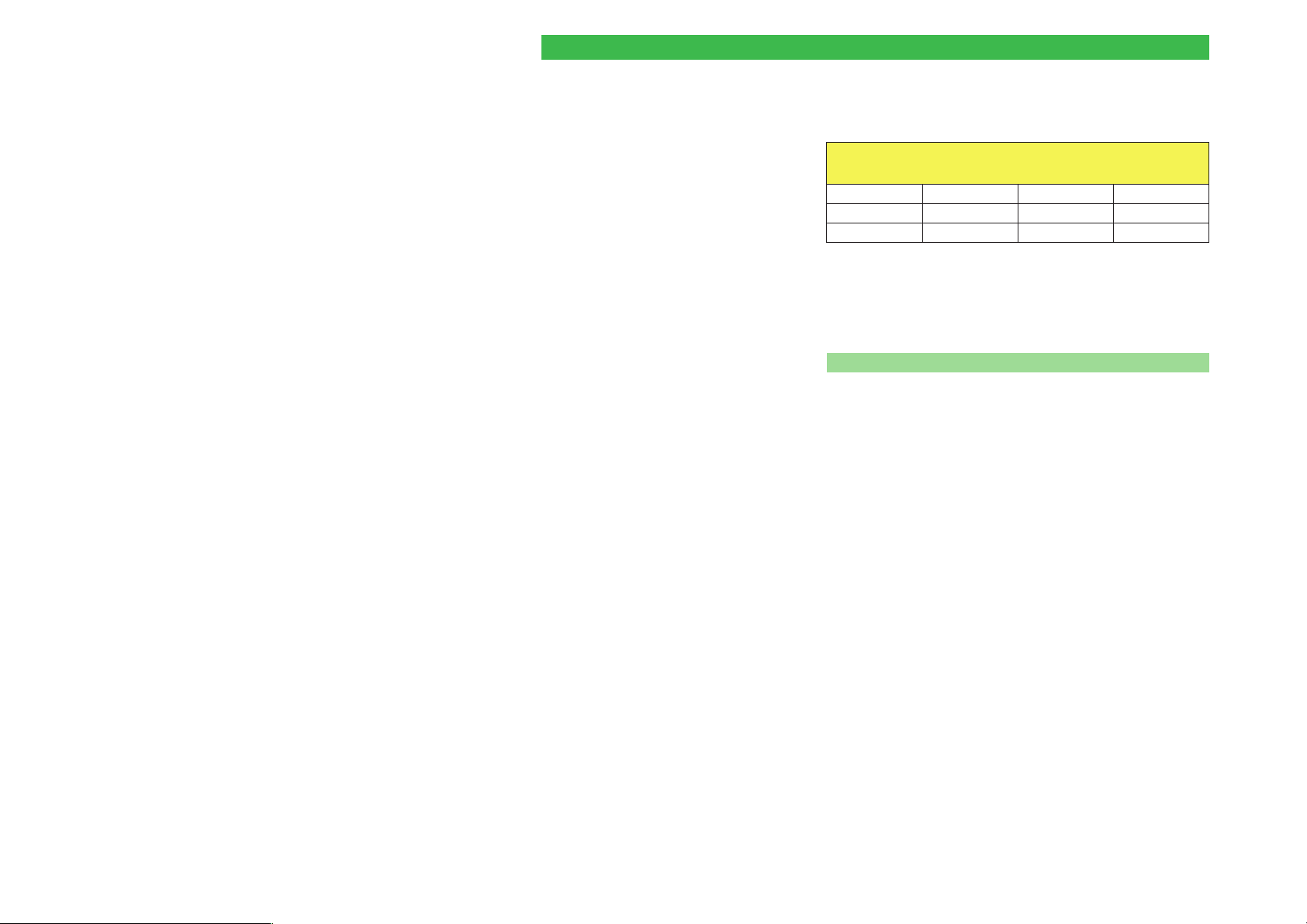
Test 4.0: Messages and measurements Willtek 4100
Depending on what RF transmit level is set, the
following limits apply under the GSM standard:
Permissible limits for BER/FER
RF level Phone BER FER
–100 dBm all 0.00 % –
–104 dBm P > 2 W < 2.44 % –
–102 dBm P £ 2 W < 2.44 % 0.10 %
% Enter the second RF transmit level in the BS Power
Level field, confirm your entry with [ENTER] and check
the measurements.
& Terminate the test with [ESCAPE].
n Test 5.0 result
The limits are not exceeded.
J
The limits are exceeded. Typical symptom: the
L
customer complains of poor speech quality or poor data
connection when using a modem.
4-28
Page 88
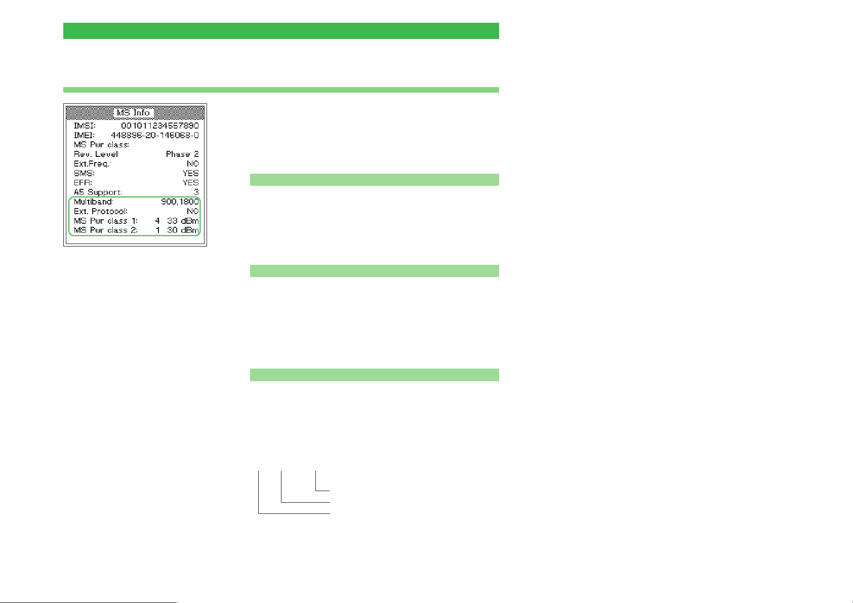
Willtek 4100 Test 6.0: Checking mobile phone identification
Test 6.0: Checking mobile phone identification
The identification data is a mobile phone's "ID card". It
provides information about the test unit which is useful
for interpreting measurements (Test 4.0) or for general
classification purposes (e.g. E-GSM mobile phone or
not?).
Preconditions for testing
n
There must be a valid telephone connection between the
l
mobile phone and the tester, set up in Test 2.0 or 3.0.
The BS CALL ACTIVE or MS CALL ACTIVE menu
l
must be visible (to get back to this menu from
lower-level menus press [ESCAPE]).
The characteristic information
highlighted in the lower part of the
display is only shown if the test unit
is a dual-band mobile phone. If you
are testing a multiband mobile
phone, the menu displays a softkey
which you can use to call up the
identification data of the 1900
band.
n Test 6.0 step by step
! Press the {MS_INFO} softkey. If this softkey is not
shown: press {MORE}.
" Check the identification data which is reported (see
"Test 6.0 results").
§ Press the [ESCAPE] key to return to the CALL ACTIVE
menu and run some other tests there.
n
Test 6.0 results
IMSI International Mobile Subscriber Identity gives important
subscriber data which is stored in the SIM. The IMSI
displayed comes from the SIM which is currently
installed in the mobile phone. The IMSI comprises the
following data:
XXX XX XXXXXXXXXX
Subscriber number within the net
Code of home network
Code of home country
The IMSI of the test SIM is: 001 01 1234567890
4-29
Page 89
Test 6.0: Checking mobile phone identification Willtek 4100
IMEI International Mobile Equipment Identity is the device
identity of the mobile phone. The IMEI comprises the
serial number, the manufacturer, the country of
manufacture and a code identifying the country in
which the mobile phone has been granted type
approval.
MS Pwr class RF power class of the mobile phone (code digit and
absolute value for the maximum RF power in dBm; This
is not displayed when testing dual-band telephones –
see below).
RF power classes
Code digit
GSM 900/E-GSM
GSM1800 (PCN)
GSM1900 (PCS)
12345
43 dBm 39 dBm 37 dBm 33 dBm 29 dBm
30 dBm 24 dBm 36 dBm – –
30 dBm 24 dBm 33 dBm – –
Rev. Level Indicates the GSM revision level of the mobile phone's
hardware and software. According to the GSM
specification the value should be Phase 1 or Phase 2.
Ext. Freq. Indicates whether the mobile phone supports the
extended channel range (E-GSM): YES or NO.
SMS Indicates whether the mobile phone supports the GSM
Short Message Service (SMS). YES or NO.
EFR Indicates whether the mobile phone supports
Enhanced Full Rate mode (improved voice quality):
YES or NO (mobile telephone only supports Full Rate
mode).
A5 Support Code number of the A5 algorithm, stored in the mobile
phone.
For data protection reasons, speech and all traffic data
are encrypted before transmission and decrypted again
at the receiving end. The code number is an integer
between 1 and 7.
4-30
Page 90

Willtek 4100 Test 6.0: Checking mobile phone identification
Dual-band mobile phone only
Multiband Indicates which frequency ranges the mobile phone
supports: 900 or 900E and 1800 or 1900.
Ext. Protocol Indicates the status of the extension bit:
NO =0,YES =1.
MS Pwr class 1 Power class of the mobile phone for GSM/E-GSM.
MS Pwr class 2 Power class of the mobile phone for GSM 1800/1900.
4-31
Page 91
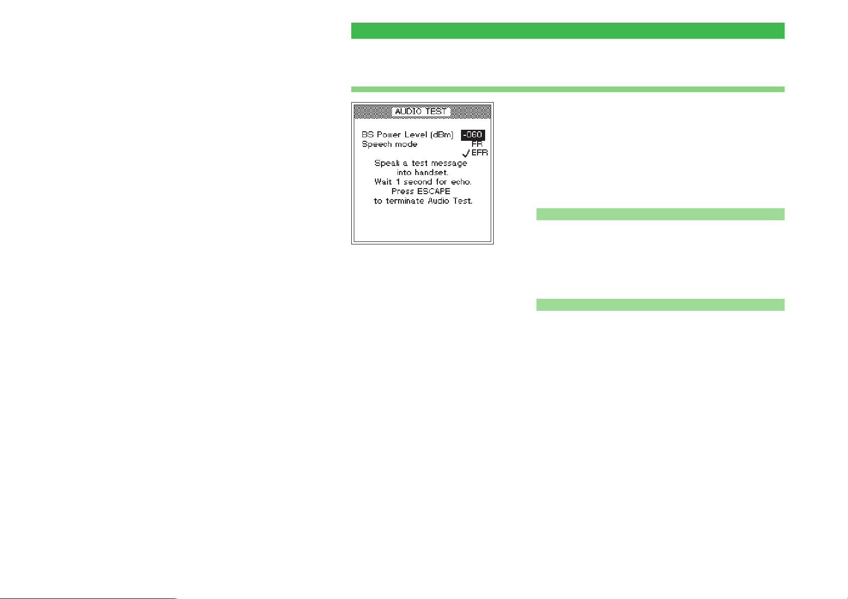
Test 7.0: Speech testing Willtek 4100
Test 7.0: Speech testing
In speech testing the test signal runs through the entire
transmission path from the mobile phone's mouthpiece
to the base station (tester) and back to the mobile
phone's earpiece. That means that the test is positive
only if all the RF and audio signal paths in the mobile
phone are intact. You can run this test as an initial
function check or for selective testing of the AF signal
paths.
Preconditions for testing
n
There must be a valid telephone connection between the
l
mobile phone and the tester, set up in Test 2.0 or 3.0.
The speech mode EFR is only
displayed if the mobile phone
supports this mode (improved
voice quality in the event of poor
reception).
The BS CALL ACTIVE or MS CALL ACTIVE menu
l
must be visible (to get back to this menu from
lower-level menus press [ESCAPE]).
n Test 7.0 step by step
! Press the {SPEECH} softkey (which calls the menu
shown on the top left of this page). If this softkey is not
shown: press {MORE}.
" Enter the BS power level of the tester in the BS Power
Level field (recommended initial value: –60 dBm).
§ If the voice codec of the mobile phone being tested
supports Enhanced Full Rate (EFR) mode, this is
displayed in addition to the standard Full Rate (FR)
mode. Only if this is the case is it possible to select the
required mode with the cursor keys and confirm your
choice with [ENTER].
$ Speak a word into the mobile phone's mouthpiece.
% After a delay of about a second you should hear the
word in the mobile phone's earpiece (echo loop).
& Repeat the speech test as many times as you like.
Reduce the BS power level of the tester each time. You
can also switch between EFR and FR modes during
testing.
4-32
Page 92
Willtek 4100 Test 7.0: Speech testing
/ Press the [ESCAPE] key to return to the CALL ACTIVE
menu and run some other tests there.
Test 7.0 result
n
Down to approx. –96 dBm, the echo should not be
J
distorted, irrespective of whether EFR or FR mode is
selected. At levels below this (approx. –102 dBm),
distortions can first be heard in FR mode and if the
level is further reduced, distortions will also be heard in
EFR mode.
No echo is heard or the echo is distorted at levels
L
significantly above –96 dBm. If the mobile phone does
not exhibit any other errors, the fault may be caused by
defective audio signal processing (defective
microphone or loudspeaker etc.).
4-33
Page 93
Test 8.0: Cell Broadcast test Willtek 4100
Test 8.0: Cell Broadcast test
In Test 8.0, the Willtek 4100 sends a text message to
the mobile phone. If the phone's decoder is in working
order, the received text is displayed.
Preconditions for testing
Cell Broadcast?
The Cell Broadcast service is
not to be confused with the SMS
(Short Message Service). SMS
enables individually addressed
messages to be sent across the
TCH.
Cell Broadcast transmits public
information (e.g. traffic reports or
match results) on a cell's BCCH.
However, the fact that a mobile
phone is able to decode SMS
texts (see test 6.0) does not automatically mean that it will also
support the Cell Broadcast service.
Message Identifier Page = 0
n
The Cell Broadcast test can only be run on test units
l
capable of receiving messages such as these.
Unfortunately, a standard procedure for ascertaining
this state does not exist. If you cannot find any menu
items on your mobile phone entitled Cell Broadcast or
Broadcast Call, it is highly likely that the device does
not support the service.
If you succeed in finding an appropriate menu item,
l
switch on the Cell Broadcast function on your mobile
phone (if the "page" is to be defined under which
messages arrive: Message Identifier Page = 0).
l
Switch off your mobile phone.
l
Carry out the usual test preparations (see page 4-4).
Your choice of TCH channel number is of no
significance. Make sure that the Willtek 4100 is
displaying the FAULT FIND menu (this means that the
tester is already broadcasting on the BCCH).
Willtek 4X00 GSM
Test - Cell
Broadcast Channel
Message
4-34
n
Test 8.0 step by step
! Switch on your mobile phone and look at the display.
n
Test 8.0 result
The text on the left appears on the phone the moment it
J
connects to the service (the appearance of the text may
differ from model to model).
The text does not appear at all or is distorted.
L
Page 94

Willtek 4100
%
Additional
Features
5-1
Page 95
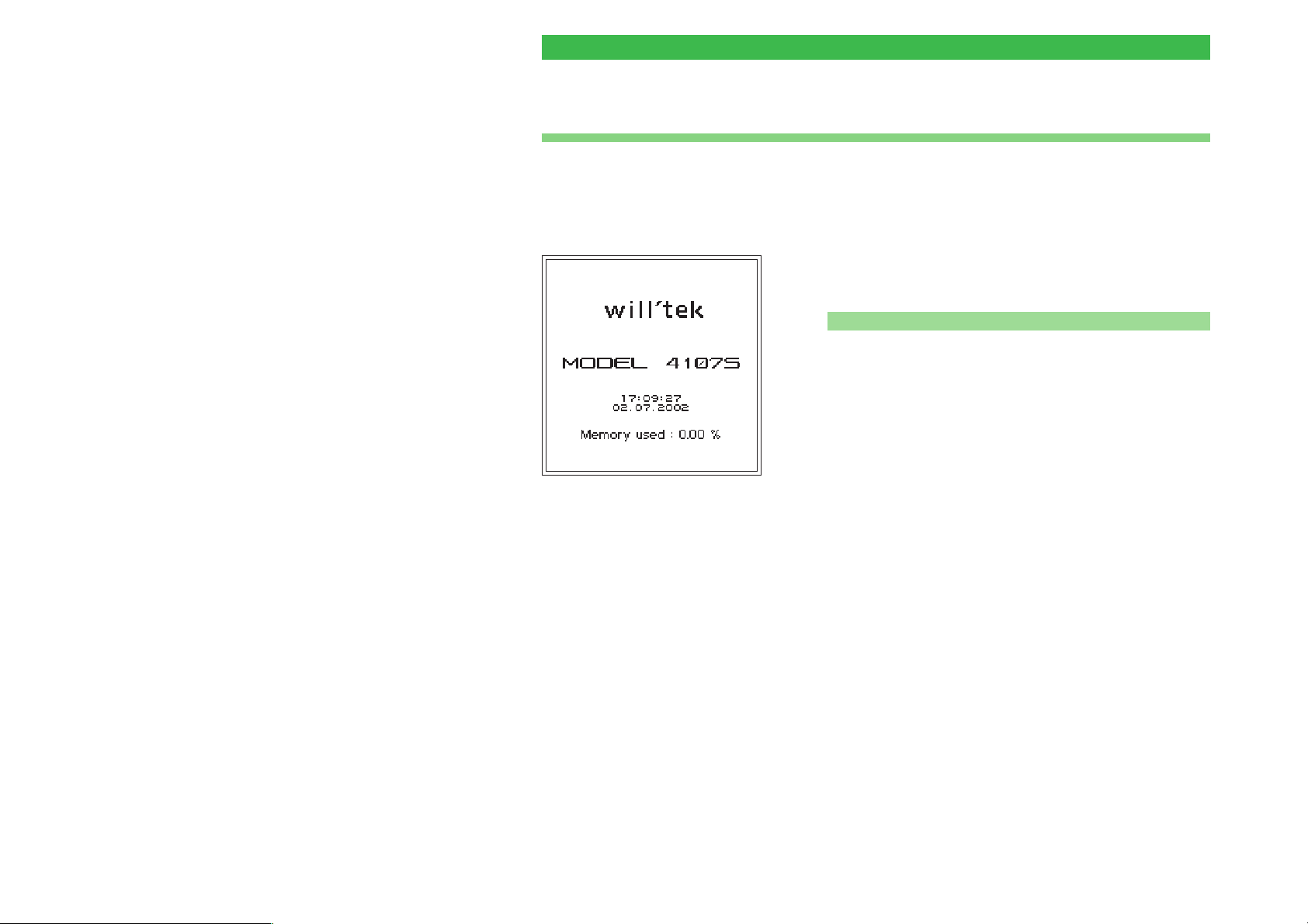
Introduction Willtek 4100
Introduction
This chapter only has any relevance for you if
+
you possess a Willtek 4107S. In case of a
Willtek 4107L the only available additional
feature is Remote Control (see page 5-8).
A Willtek 4107S has all the same characteristics as the
corresponding standard model, but also provides a
number of additional features.
Additional features
n
Asynchronous Mode: The tester evaluates the signals
l
sent by a GSM telephone in test mode. In Asynchronous Mode, the tester indicates together with other data,
information on the RF signal bursts.
Detailed display of where the power-time template has
l
been violated.
l
Emission of an unmodulated or defined, modulated
carrier signal.
l
Remote Control of the tester using SCPI commands
over the RS-232-C interface (making settings on the
tester and querying test results).
5-2
Page 96

Willtek 4100 Asynchronous Mode
Asynchronous Mode
Any GSM mobile phone can be set to "test mode". How
this is achieved and what features are available on a
mobile phone in test mode vary from manufacturer to
manufacturer. It is therefore not possible to provide
generally valid instructions in this document.
Once a mobile phone has been set to test mode, it will
generally no longer react to normal signals. This means
that settings have to be carried out on the mobile
phone itself (either manually or under Remote Control).
In Asynchronous Mode, the Willtek 4107S and the
mobile phone do not exchange signals. Instead, the
tester is permanently set to receive and is able to
evaluate the RF signals from the mobile phone.
5-3
Page 97
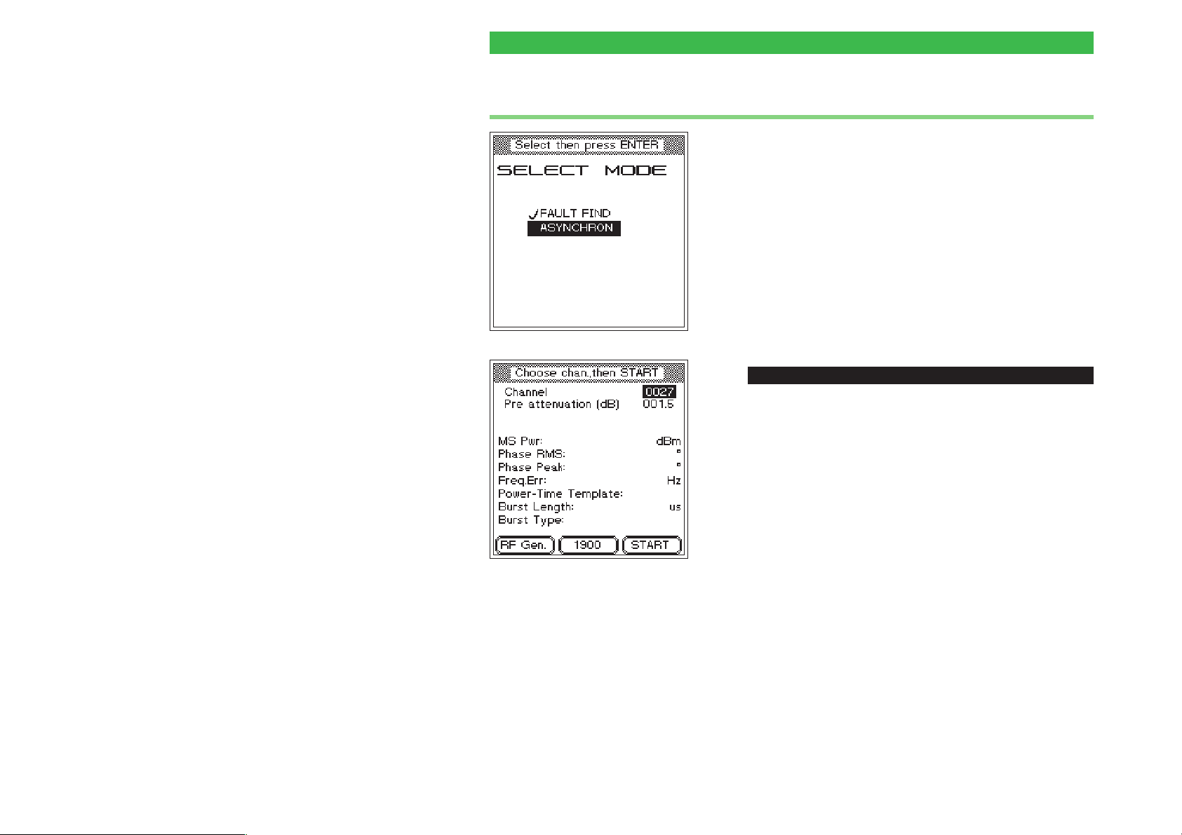
Asynchronous Mode Willtek 4100
Preparation and starting
! Connect the mobile phone to the tester and set it to test
mode according to the manufacturer's instructions.
" Set the required test parameters (e.g. channel number,
power level) on the mobile phone according to the
manufacturer's instructions.
§ Press [FAULT_FIND] on the Willtek 4107S, use the
cursor keys to select a radio system which matches the
mobile phone and confirm your selection with [ENTER].
$ Choose ASYNCHRON from the SELECT MODE menu
and confirm your choice with [ENTER]. You will now
see the test menu.
The {1900} softkey only appears if
you have selected a multiband
radio system.
ï
[FAULT_FIND] + ASYNCHRON + [ENTER]
% Enter the channel number you set on the mobile phone
in the Channel input field and confirm your entry with
[ENTER]. You do not have to distinguish between TCH
and BCCH as the channel number is only used to tune
the receiver in the Willtek 4107S.
& Choose {START} to start measuring in Asynchronous
Mode. The tester will now measure continuously,
updating every 2.5 seconds until you choose [ESCAPE].
The channel number cannot be changed during
measurement.
Test mode must be terminated on the mobile
+
phone after the measurements have been
completed or before FAULT FIND mode or
RF Gen. is called, for example.
5-4
Page 98
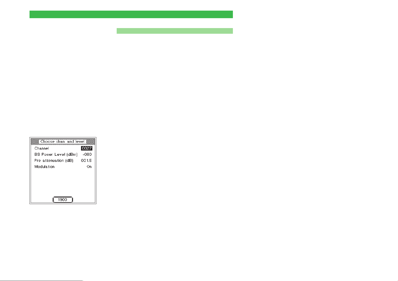
Willtek 4100 Asynchronous Mode
Changing bands on multiband devices
n
If you want to change between the 900/1800 and 1900
bands when testing a multiband phone, proceed as
follows:
! Terminate the current measurement (e.g. in the
900/1800 band) by pressing [ESCAPE].
" Terminate test mode on the mobile phone.
§ Switch the tester to the new band (e.g. the 1900 band)
using the softkey.
$ Set the mobile phone to test mode again and set the
new band.
% Set the new channel number on the mobile phone and
on the tester and press {START} to continue the
measurement.
Emission of a carrier signal
It may be appropriate to feed a defined carrier signal
into the mobile phone for test and adjustment
purposes. This function is available if you press
{RF_Gen.}. As soon as the menu shown on the left
appears, the Willtek 4107S sends a carrier signal
defined by the values entered in the menu. You can
toggle between the values On and Off for Modulation
by selecting the field with the cursor keys and then
pressing [ENTER].
When Modulation is set to On, the frequency of the
carrier signal is offset by +67.7 kHz (relative to the
current channel frequency). This corresponds to a
digital modulation signal in the form 111111...
Press [ESCAPE] to deactivate emission of the carrier
signal.
5-5
Page 99
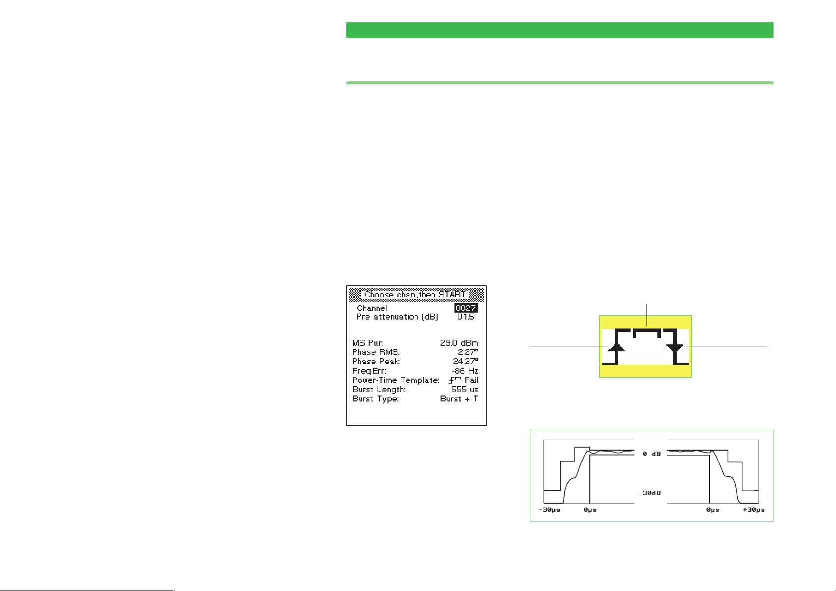
Asynchronous Mode Willtek 4100
Test results in Asynchronous Mode
The Willtek 4107S displays the following
measurements and messages in Asynchronous Mode:
MS Pwr RF transmit power of the mobile phone.
Phase RMS Phase errors of the GSM burst signal (average value).
Phase Peak Phase errors of the GSM burst signal (peak value).
Freq.Err Frequency error of the RF carrier signal.
Power-Time Template Assessment of whether the GSM burst signal lies within
the tolerance zones of the template.
Pass Burst profile is error free.
Fail Burst profile exceeds the tolerance limits at one or
more locations. Three symbols indicate the locations
where the tolerance zones were exceeded. These
symbols (the Burst Edge Failure Indication) can appear
on their own or in combination with the other symbols.
Error in horizontal section of burst waveform
5-6
Error on
rising burst
edge
Error on
falling burst
edge
The following diagram illustrates the zones of the
power-time template.
Page 100

Willtek 4100 Asynchronous Mode
Burst Length Length of the GSM burst.
Burst Type Detailed information on the characteristics of the GSM
burst. The tester derives this information by comparing
the received bursts with stored reference patterns. The
following messages may appear, depending on the
result:
Burst + T Burst with training sequence.
Cont. The mobile phone transmits a continuous GMSK
modulated RF signal rather than bursts.
—- No detailed information available on the signal.
5-7
 Loading...