

Wills Wing Ultra Sport 135, Ultra Sport 147, Ultra Sport 166 Owner's Service Manual
Ultra Sport 135,147,166
Owner / Service Manual
July 1998 - Third Edition

Ultra Sport 135,147,166
Owner / Service Manual
Copyright © 1994, 1995, 1996, 1997,1998 by Sport Kites, Inc. dba Wills Wing, Inc. All rights reserved.
No part of this manual may be reproduced in any form without the express written permission of
Sport Kites, Inc., dba Wills Wing, Inc.
July 1998 - Third Edition
500 West Blueridge Ave Orange, CA 92865 Phone (714) 998-6359 FAX (714) 998-0647
Internet Web address: http://www.willswing.com E-mail: comments@willswing.com


Contents
Introduction...................................................................................................... 1
Disclaimer and Warning ...................................................................................... 2
Technical Information and Placarded Operating Limitations ...................................... 3
Ultra Sport Breakdown Procedure for Shipping and Reassembly Procedure ................ 6
Ultra Sport Set-Up Procedure .............................................................................. 7
Preflight Procedure .......................................................................................... 12
Laying the Glider Down Flat .............................................................................. 15
Setting the Glider Up Flat on the Ground ............................................................ 15
Launching and Flying the Ultra Sport.................................................................. 16
Trimming Your Glider in Pitch ............................................................................ 19
Speeds to Fly and Using a Hall Airspeed Indicator................................................ 20
Using the VG System ...................................................................................... 21
Flying Fast Without Oscillations ........................................................................ 21
Landing the Ultra Sport .................................................................................... 23
Ultra Sport Breakdown ..................................................................................... 25
Ultra Sport Stability Systems ............................................................................ 26
Ultra Sport Reflex Bridle Adjustment and Flight Testing ......................................... 26
Maintenance................................................................................................... 29
Removing the Sail from the Airframe and Re-Installing.......................................... 31
Glider Tuning .................................................................................................. 33
Car Top Mounting and Transport ........................................................................ 36
In Closing....................................................................................................... 36
Ultra Sport 135, 147, 166 Assembly DiagramsTable of Contents ...................... A-1
Ultra Sport 147 Middle/Rear Keel.................................................................................. A-2
Ultra Sport 147 VG Assembly ........................................................................................ A-3
Ultra Sport 147 Crossbar Assembly ............................................................................... A-4
Ultra Sport 147 Noseplate Assembly.............................................................................. A-5
Ultra Sport 147 Kingpost Assembly ............................................................................... A-6
Ultra Sport 135 and 166 Rear Keel ................................................................................ A-7
Ultra Sport 135 and 166 Middle Keel ............................................................................ A-8
Ultra Sport 135 and 166 Cam VG .................................................................................. A-9
Ultra Sport 135 and 166 Crossbar Center..................................................................... A-10
Ultra Sport 135 and 166 Noseplate............................................................................... A-11
Ultra Sport 135 and 166 Kingpost ................................................................................ A-12
VG Control Bar Assembly ............................................................................................ A-13
VG Folding Basetube Assembly................................................................................... A-14
Ultra Sport Rear Leading Edge Assembly.................................................................... A-15
Ultra Sport Control Bar Specifications......................................................................... A-16
Ultra Sport 147 Airframe .............................................................................................. A-17
Ultra Sport 166 Airframe .............................................................................................. A-18
Ultra Sport 135 Airframe .............................................................................................. A-19
Control Bar Apex Button Lock ..................................................................................... A-20


Introduction
Thank you for purchasing a Wills Wing glider, and welcome to the world wide family of Wills Wing
pilots. We are a company of pilots and aviation enthusiasts, and our goal is to serve your flying needs
now and in the future, as we have done for pilots throughout the world since 1973.
We encourage you to read this manual thoroughly for information on the proper use and maintenance
of your Wills Wing glider. If at any time you have questions about your glider, or about any aspect of
hang gliding that your Wills Wing dealer cannot answer, please feel free to give us a call.
If you have access to the Internet, please visit us at http://www.willswing.com. The site features
extensive information about Wills Wing gliders and products, a Wills Wing Dealer directory, our
complete retail price list, a site search engine, and more.
The most important contents of our internet site are the service and technical bulletins, and the latest
editions of owners manuals. This is your single best source for safety and airworthiness advisories on
Wills Wing products. Many of the documents are published in Adobe Acrobat format. A free viewer for
Acrobat files is available at http://www.adobe.com.
We wish you a safe and enjoyable flying career, and, once again, welcome aboard!
Rob Kells, Mike Meier, Linda Meier, and Steve Pearson
Wills Wing, Inc.
1

Disclaimer and Warning
Hang gliding is a form of aviation. Like any form of aviation, its safe practice demands the consistent
exercise of pilot skill, knowledge of airmanship and weather, judgment and attention at a level which is
appropriate to the demands of each individual situation. Pilots who do not possess or exercise the
required knowledge, skills and judgment are frequently injured and killed. The statistical rate at which
fatalities occur in hang gliding is approximately one per thousand participants per year.
The Federal Aviation Administration does not require a pilots license to operate a hang glider. Hang
gliders and hang gliding equipment are not designed, manufactured, tested or certified to any state or
federal government airworthiness standards or requirements. Federal Aviation Regulation Part 103
states in part, "ultralight vehicles are not required meet the airworthiness certification standards
specified for aircraft or to have certificates of airworthiness" and "operators of ultralight vehicles are
not required to meet any aeronautical knowledge, age, or experience requirements to operate those
vehicles or to have airman or medical certificates." Wills Wing hang gliding products are not covered
by product liability insurance. As a hang glider pilot, you are entirely responsible for your own safety.
You should never attempt to fly a hang glider without having received competent instruction. We
strongly recommend that you not participate in hang gliding unless you recognize fully and wish to
personally assume all of the associated risks.
Please fly safely.
Wills Wing, Inc.
2

Technical Information and Placarded Operating Limitations
The Ultra Sport 135, 147 and 166 have been tested and found to comply with the Hang Glider Manufacturers Association (HGMA) Airworthiness Standards. These standards require:
1. A positive load test at root stall angle of attack at a speed equal to at least the greatest of:
a. 141% of the placarded maximum maneuvering speed
b. 141% of the placarded maximum rough air speed
c. 123% of the placarded speed never to exceed
for at least three seconds without failure.
The required speed for the Ultra Sport for this test was 65 m.p.h..
2. A negative 30 degree angle of attack load test at a speed equal to at least the greatest of:
a. 100% of the placarded maximum maneuvering speed
b. 100% of the placarded maximum rough air speed
c. 87% of the placarded speed never to exceed
for at least 3 seconds without failure.
The required speed for the Ultra Sport for this test was 46 m.p.h..
3. A negative 150 degree angle of attack load test at a speed equal to at least the greater of 30 m.p.h.
or 50% of the required positive load test speed for at least 3 seconds without failure.
The required speed for the Ultra Sport for this test was 32 m.p.h..
4. For the Ultra Sport with a Vne of 53 m.p.h., pitch tests at speeds of 20 m.p.h., 37 m.p.h. and 53
m.p.h. which show the glider to be stable over a range of angles of attack from trim angle to 20
degrees below zero lift angle at 20 m.p.h., and from trim angle to 10 degrees below zero lift angle
at 37 m.p.h., and from 10 degrees above zero lift angle to zero lift angle at 53 m.p.h..
5. Flight maneuvers which show the glider to be adequately stable and controllable throughout the
normal range of operation.
NOTE: The Ultra Sport has been designed for foot launched soaring flight. It has not been designed to
be motorized, tethered, or towed. It can be towed successfully using proper procedures. Pilots wishing
to tow should be USHGA skill rated for towing, and should avail themselves of all available information on the most current proper and safe towing procedures. Suggested sources for towing information
include the United States Hang Gliding Association and the manufacturer of the towing winch / or
equipment being used. Wills Wing makes no warranty of the suitability of the glider for towing.
Flight operation of the Ultra Sport should be limited to non aerobatic maneuvers; those in which the
pitch angle will not exceed 30 degrees nose up or nose down from the horizon, and the bank angle will
not exceed 60 degrees. The Ultra Sport is generally resistant to spinning, but may spin from a stalled
turn, especially if the VG is adjusted at or near the tight end of the range, and the rate of application of
pitch is moderately rapid. The Ultra Sport can be induced to spin at any VG setting. Recovery from a
spin requires unstalling of the wing, and it is therefore critically important that in the event of a spin,
no application of nose up pitch control be held. The Ultra Sport will recover from a spin once control
pressures are relaxed. As the nose lowers and the angle of attack is reduced, the stall will be broken
3

and the spin will stop. However, such recovery will consume significant altitude, and will result in the
glider assuming an unpredictable heading. Recovery from a spin may therefore involve a flight trajectory which intersects the terrain at a high rate of speed. An aggravated spin could result in loss of
control, in flight inversion, and structural failure. Therefore no attempt should ever be made to deliberately spin the glider. The Ultra Sport provides the pilot with a high degree of pitch authority, in combination with a very low twist sail. As a result, it is possible by pushing fully out on the bar to produce a
very aggravated and severe stall, the recovery from which may involve very severe pitch down rotation,
the pilot going weightless, and the glider recovering via an unpredictable trajectory with a significant
altitude loss. Therefore, full arms extension aggravated stalls should not be induced except on landing
flare.
The maximum steady state speed for a prone pilot in the middle of the recommended weight range full
forward on the control bar with the VG set full tight is approximately 53 m.p.h. for the Ultra Sport 147
and 50 m.p.h. for the Ultra Sport 135 and 166. The placarded speed never to exceed for the Ultra Sport
is 53 m.p.h.. An optional airspeed indicator is available for the Ultra Sport and can be used by the
pilot as an aid to comply with the placarded limitations.
The placarded maximum maneuvering speed, and the placarded maximum rough air speed of the Ultra
Sport are each 46 m.p.h.. This speed will be achieved with the control bar basetube approximately six
inches below the waist. This speed should not be exceeded in anything other than smooth air. No
abrupt maneuvering or control inputs should be made at anything above this speed.
The stability, controllability, and structural strength of a properly maintained Ultra Sport have been
determined to be adequate for safe operation when the glider is operated within all of the manufacturer
specified limitations. No warranty of adequate stability, controllability, or structural strength is made
or implied for operation outside of these limitations.
The stall speed of the Ultra Sport at maximum recommended wing loading is 25 m.p.h. or less. The top
(steady state) speed at minimum recommended wing loading for a prone pilot with a properly designed
and adjusted harness is at least 42 m.p.h.. All speeds given above are indicated airspeeds, for a properly calibrated airspeed indicator mounted in the vicinity of the pilot. Wills Wing sells such an airspeed
indicator as an accessory. It is recommended that the pilot fly with such an airspeed indicator. Refer to
the section on using the airspeed indicator for further information on speeds to fly.
The recommended hook in pilot weight range for the Ultra Sport is:
Ultra Sport 135: 125 - 210 lbs.
Ultra Sport 147: 150 - 250 lbs.
Ultra Sport 166: 175 - 285 lbs.
Be advised that pilots with hook in weights of less than 20 lbs above minimum will find the Ultra Sport
more demanding of pilot skill to fly, and that pilots hooking in within 20 lbs of the maximum will
experience some relative degradation of optimum sink rate performance due to their higher wing
loading.
A minimum USHGA Intermediate (III) level of pilot proficiency is required to fly the Ultra Sport
safely. Pilots are advised that the optimum proficiency level for the Ultra Sport is higher than the
minimum recommended. Operation of the glider by unqualified or under qualified pilots may be
dangerous.
4

Operating the Ultra Sport outside of the above limitations may result in injury and death. Flying the
Ultra Sport in the presence of strong or gusty winds, or turbulence may result in loss of control of the
glider which may lead to injury and death. Do not fly in such conditions unless you realize and wish to
personally assume the associated risks. Wills Wing is well aware that pilots have, and continue to
perform maneuvers and fly in conditions which are outside the recommended operating limitations
stated herein. Please be aware that the fact that some pilots have exceeded these limitations in the past
without dangerous incident does not imply or insure that the limitations may be exceeded without risk.
We do know that gliders which meet all current industry standards for airworthiness can and do suffer
in flight structural failures, both as a result of turbulence, and as a result of various maneuvers outside
the placarded operating limitations, including, but not necessarily limited to aerobatics. We do not
know, and cannot know, the full range of maneuvers or conditions which may cause the pilots safety to
be compromised, nor can we test the glider in all possible circumstances.
5

Ultra Sport Breakdown Procedure for Shipping and Reassembly
Procedure
The front leading edge is 50mm (1.97") oversleeved with 52mm (2.05") at the crossbar junction. The
rear leading edge is 50mm and slotted at the forward end and engages in a clevis in the 52mm
oversleeve.
To break down the leading edges follow these steps
1. Lay the glider on the ground or floor, unzip and remove the bag and remove the velcro ties. Undo
the velcros which hold the sail around the sail mount plug and pull the sail rearward at each tip to
dismount the sail mount webbing from the slotted endcap. You may find it helpful to use a large,
flat bladed screw driver to pry the webbing out of the slot and over the endcap. Take care not to
damage the webbing.
2. Obtain an indelible marker. Mark the rear leading edges left and right (remember that left and right
are reversed if the glider is lying on its back, upside down). Push the sail up to where you have
uncovered the point where the rear leading edge exits the front. Trace around the circumference of
the 50 mm rear leading edge just along the aft edge of the 52mm oversleeve so as to mark the point
at which the rear leading edge is fully engaged in the front.
3. Scribe a line along the leading edge which crosses the rear leading edge to 52mm oversleeve
junction. This will help to align the rear leading edge during reassembly.
4. Pull the rear leading edge straight aft to disengage it from the front. Put tape or padding on the
sharp edges of the front end of the rear leading edge tubes.
5. Carefully fold the rear of the sail over against the front, and replace the bag on the glider.
Remounting the rear leading edges
1. Make sure you are mounting the correct leading edge rear into the correct front (check the right /
left designation).
2. Spray the forward six inches of the rear leading edge with silicone spray lubricant.
3. Slide the rear leading edge into the front, lining up the rotational alignment marks you made during
breakdown, until the rear engages fully in the front leading edge, as indicated by the circumferential scribe made at the exit point of the rear leading edge during breakdown.
4. Pull the sail down the leading edge and reinstall the mylar if removed. The mylar is most easily
installed by attaching it to a long pole and pushing it into the pocket.
5. Reinstall the top side wire if removed.
6. Remount the sail to the rear leading edge, making sure to align the sail mount webbing squarely in
the slot and attach the securing velcros. Again, you may find it helpful to use a large, flat blade
screwdriver to pry the webbing over the end of the leading edge and into the slot.
The sail is mounted to the leading edge by the inner (forward) of the two loops of webbing. The outer loop is a pull handle only.
6
Ultra Sport Set-Up Procedure
The Ultra Sport has been specially designed to set up quickly and easily either on the control bar or flat
on the ground. We will first cover the steps for setting up on the control bar.
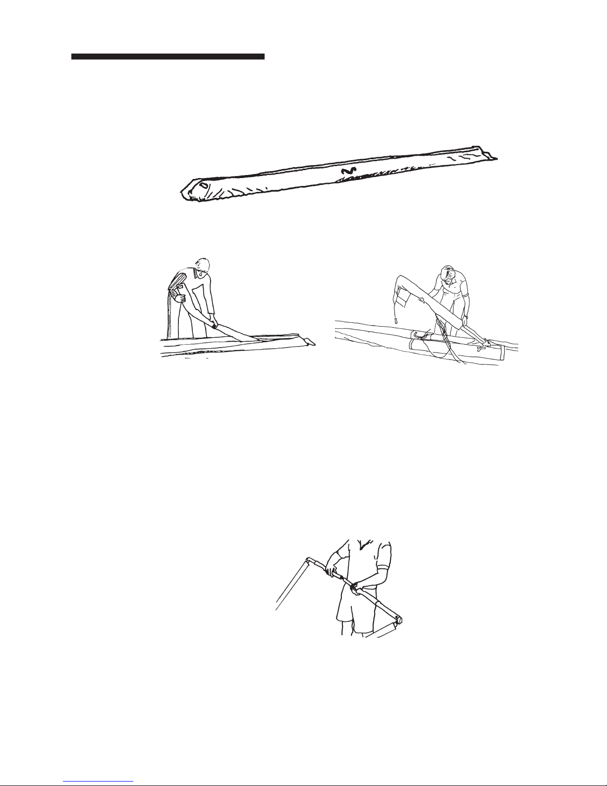
1. Lay the glider on the ground, with the bag zipper up, with the nose into the wind.
2. Undo the zipper and remove the battens. Slide the neoprene sock at the end of the keel tube for-
ward until the end of the keel is exposed. Slide the neoprene sock covering the rear wire junction
aft until the wire junction is exposed. Remove the control bar bag.
3. Unfold the control bar legs.
a. If the glider is equipped with a folding basetube:
i. Straighten the fold in the folding basetube.
ii. Preflight the folding basetube center hardware at this time, checking that the nuts
and coil spring pins are secure, and that the tangs are straight and in good condition.
iii. Slide the basetube center sleeve over the center joint until it is positioned between
the button spring pins. (Note: If you plan to clamp instruments to the basetube
center, position the center sleeve so that one button passes through the hole near
one end of the sleeve, which will secure the sleeve against rotation.
b. If the glider is equipped with a non folding basetube:
i. Remove the safety ring, wing nut and bolt from the corner bracket.
ii. Insert the corner bracket all the way into the basetube.
iii. Install the bolt, wingnut and safety, securing the bracket to the basetube.
7
Make sure that the aluminum fitting is fully inserted into the basetube, and that the bolt is through
both the basetube and the fitting. If the hole in the fitting can be seen outside the end of the
basetube, the fitting is not fully installed, and will likely disengage in flight resulting in a dangerous
structural collapse and loss of control of the glider.
Do not insert the fitting at an angle, and do not force the fitting into the basetube if it does not slide
in freely. Check for dirt or damage to the fitting or the inside of the basetube. If the fitting is forced
into the basetube, it may be impossible to remove. See your dealer if the fitting becomes difficult to
install or remove.
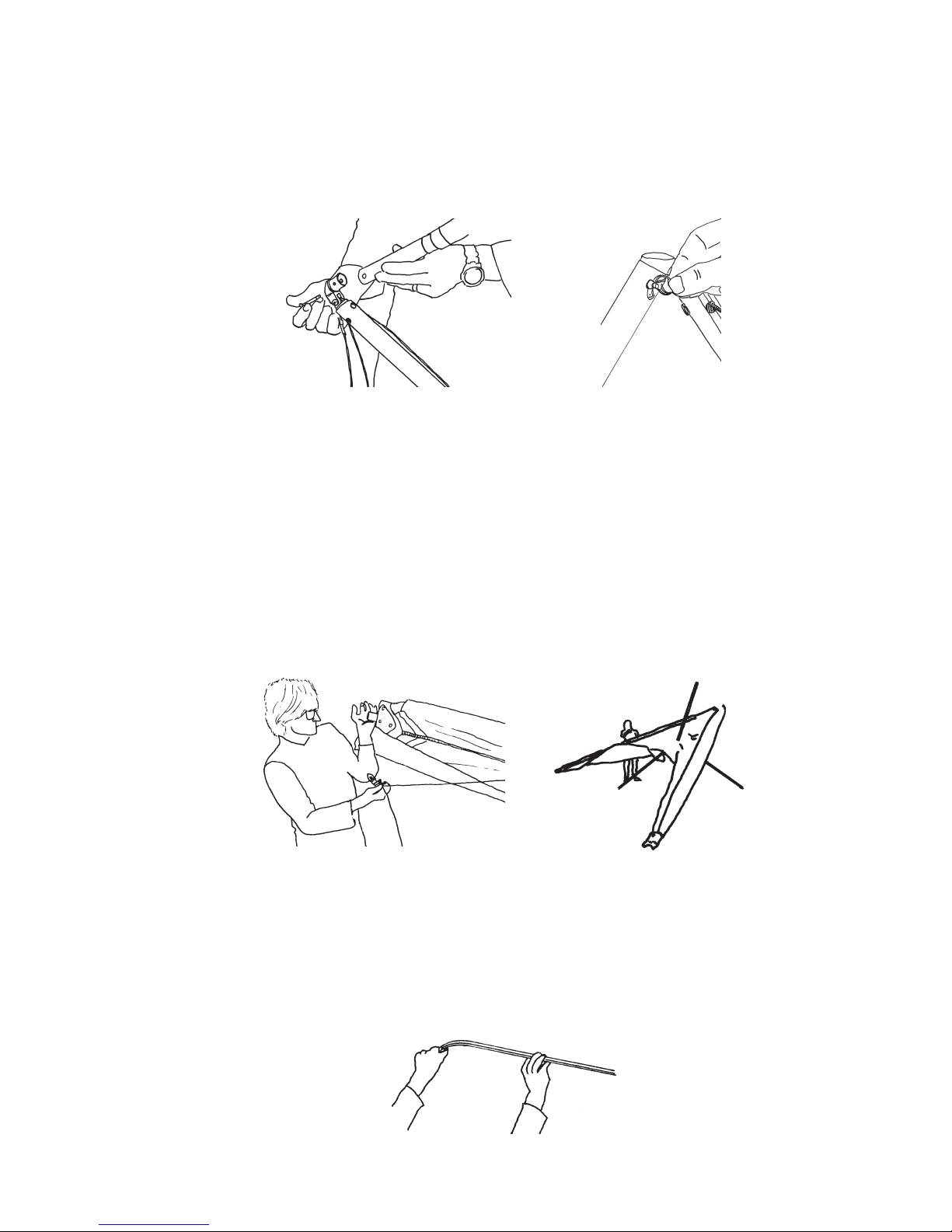
4. Flip the glider upright on the control bar, and remove the bag and all the velcro ties. Do not remove
the leading edge tip protector bags at this time, but do loosen the velcros on the tip bags. If there is
more than eight m.p.h. of wind, or if the wind is gusty, turn the glider 90 degrees to the wind
direction.
5. Spread the wings almost all the way. If you have left the bridles attached, this will automatically
stand the kingpost upright. If not, lift on the top side wire as you spread the second wing, and the
kingpost will stand up.
6. If the bridles have been detached, attach the bridle ring to the snap hook at this time, taking care
that there is not a twist or rotation in the bridle ring which causes the bridle line to cross over one
another.
7. Remove the battens from the batten bag, and check each batten for symmetry against the corresponding batten from the other wing. Wills Wing convention is that black tipped battens go in the
right wing and white tipped battens in the left, except for the straight #1 plug on battens which all
have black tips.
8
 Loading...