

Wills Wing T2 144, T2 154, T2C 136, T2C 144, T2C 154 Owner's Service Manual

T2 144, 154
and T2C 136, 144, 154
Owner / Service Manual
September 2012 - Fifth Edition


T2 144, 154
and T2C 136, 144, 154
Owner / Service Manual
September 2012 - Fifth Edition
Copyright © 1994 - 2012 by Sport Kites, Inc. dba Wills Wing, Inc. All rights reserved. No part of this
manual may be reproduced in any form without the express written permission of Sport Kites, Inc., dba
Wills Wing, Inc.
500 West Blueridge Ave • Orange, CA • 92865 • Phone (714) 998-6359 • FAX (714) 998-0647
Web address: http://www.willswing.com • E-mail: comments@willswing.com


Introduction
Thank you for purchasing a Wills Wing glider, and welcome to the world wide family of Wills Wing
pilots. We are a company of pilots and aviation enthusiasts, and our goal is to serve your ying needs now
and in the future, as we have done for pilots throughout the world since 1973.
We encourage you to read this manual thoroughly for information on the proper use and maintenance of
your Wills Wing glider. If at any time you have questions about your glider, or about any aspect of hang
gliding that your Wills Wing dealer cannot answer, please feel free to give us a call.
Because there is no regulation that requires the registration of hang gliders, Wills Wing has no way to
maintain an accurate contact list of the owners of the hang gliders we manufacture. As a result, Wills
Wing has no reliable way to contact owners directly about service and safety issues. It is therefore, of necessity, your responsibility as an owner to check periodically for service advisories and technical updates
that relate you your glider. You can do so most effectively by going to our web site at www.willswing.
com. The site features extensive information about Wills Wing gliders and products, a Wills Wing Dealer
directory, a comprehensive list of service and technical bulletins, the latest editions of owners manuals,
our complete retail price list, a search engine, e-mail and more.
The most important contents of our internet site are the service and technical bulletins, technical articles,
and the latest editions of owner’s manuals. These are your best sources for safety and airworthiness advisories and information on Wills Wing products. Many of the documents are published in Adobe Acrobat
format. A free viewer for Acrobat les is available at http://www.adobe.com. Note that it is best to have
the most current available release of the viewer for Acrobat les, as newer les may not display properly
in earlier versions.
If you are unable to obtain service information from the web site, you can contact us by email, by U.S.
mail, or by telephone.
We wish you a safe and enjoyable ying career, and, once again, welcome aboard!
Mike Meier, Linda Meier, and Steven Pearson
Wills Wing, Inc.
— 1 —

Disclaimer and Warning
Hang gliding is a form of aviation. Like any form of aviation, its safe practice demands the consistent
exercise of pilot skill, knowledge of airmanship and weather, judgment and attention at a level that is appropriate to the demands of each individual situation. Pilots who do not possess or exercise the required
knowledge, skills and judgment are frequently injured and killed. The statistical rate at which fatalities
occur in hang gliding is approximately one per thousand participants per year.
The Federal Aviation Administration does not require a pilot’s license to operate a hang glider. Hang glid-
ers and hang gliding equipment are not designed, manufactured, tested or certied to any state or federal
government airworthiness standards or requirements. Federal Aviation Regulation Part 103 states in part,
“ultralight vehicles are not required meet the airworthiness certication standards specied for aircraft
or to have certicates of airworthiness” and “operators of ultralight vehicles are not required to meet any
aeronautical knowledge, age, or experience requirements to operate those vehicles or to have airman or
medical certicates.” Wills Wing hang gliding products are not covered by product liability insurance.
As a hang glider pilot, you are entirely responsible for your own safety. You should never attempt to y a
hang glider without having received competent instruction. We strongly recommend that you not participate in hang gliding unless you recognize fully and wish to personally assume all of the associated risks.
Please y safely.
— 2 —

Technical Information and Placarded Operating Limitations
The T2 144, T2 154, T2C 144 and T2C 154 have been tested and found to comply with the Hang Glider
Manufacturers Association (HGMA) Airworthiness Standards. Certicates of Compliance were granted
by the HGMA on the following dates:
T2 144 May 22, 2006
T2 154 October 6, 2006
T2C 144 May 19, 2009
T2C 154 June 16, 2009
T2C 136 *
* HGMA compliance testing had been completed but not submitted for review by the HGMA as of September 10th, 2012
Also, on December 22, 2008, the DHV Technical Department, an approved testing center for hang gliders
and paragliders for the LBA (German Civil Aviation Authorities), issued a Gütesiegel for the Wills Wing
T2C 154 hang gliders, signifying that this glider meets the German LTF Airworthiness Standards for hang
gliders.
Updated information on the current HGMA certication status of any hang glider can be found on the
HMGA web site at www.hgma.net
The HGMA standards require:
1. A positive load test at root stall angle of attack at a speed equal to at least the greatest of:
a. 141% of the placarded maximum maneuvering speed
b. 141% of the placarded maximum rough air speed
c. 123% of the placarded speed never to exceed for at least three seconds without failure.
The required speed for the T2 for this test was 65 m.p.h.
2. A negative 30-degree angle of attack load test at a speed equal to at least the greatest of:
a. 100% of the placarded maximum maneuvering speed
b. 100% of the placarded maximum rough air speed
c. 87% of the placarded speed never to exceed for at least 3 seconds without failure.
The required speed for the T2 for this test was 46 m.p.h.
3. A negative 150 degree angle of attack load test at a speed equal to at least the greater of 30 m.p.h.
or 50% of the required positive load test speed for at least 3 seconds without failure.
The required speed for the T2 for this test was 32 m.p.h.
4. For the T2 with a Vne of 53 m.p.h., pitch tests at speeds of 20 m.p.h., 37 m.p.h. and 53 m.p.h.
which show the glider to be stable over a range of angles of attack from trim angle to 20 degrees
below zero lift angle at 20 m.p.h., and from trim angle to 10 degrees below zero lift angle at 37
m.p.h., and from 10 degrees above zero lift angle to zero lift angle at 53 m.p.h.
5. Flight maneuvers which show the glider to be adequately stable and controllable throughout the
normal range of operation.
Note: The T2 has been designed for foot launched soaring ight. It has not been designed to be motorized,
tethered, or towed. It can be towed successfully using proper procedures. Pilots wishing to tow should
— 3 —

be USHGA skill rated for towing, and should avail themselves of all available information on the most
current proper and safe towing procedures. Suggested sources for towing information include the United
States Hang Gliding Association and the manufacturer of the towing winch / or equipment being used.
Wills Wing makes no warranty of the suitability of the glider for towing.
Because of the design of the nose catch for the bottom front wires on the T2 it is critically important that
the nose line be attached properly during platform towing operations. In no case should the nose line be
attached in such a way that there is any possibility that the nose line can pull forward on the nose wires,
nose tang or nose tang handle, or, in any other way, contribute to disengagement of the nose wires. Please
read the section on towing for more information.
Because of the lack of a kingpost and top rigging on the T2 design, tethering the glider by the nose, such
as is commonly done during platform towing operations, creates the potential for overloading the keel
tube of the glider which could result in a structural failure. To avoid overloading the keel, any tether line
attached to the nose should pull as much as possible in line with the keel, and in no case in a direction
more than 45 degrees below the line of the keel tube itself. Please read the section on towing for more
information.
Flight operation of the T2 should be limited to non aerobatic maneuvers; those in which the pitch angle
will not exceed 30 degrees nose up or nose down from the horizon, and the bank angle will not exceed 60
degrees. The T2 can be induced to spin at any VG setting. At VG settings of less than 50% (VG middle
or looser) the T2 is moderately resistant to spinning, and has spin and spin recovery characteristics that
are typical for other Wills Wing high performance ex wing gliders. At VG settings greater than 50%
(VGM to VG full tight), the T2 becomes progressively and rapidly more susceptible to spinning, and the
spin characteristics and spin recovery characteristics become markedly more extreme. In the most ex-
treme case, a spin entry at VG full tight (VGT), initiated by a rapid pitch up to a signicantly nose high
attitude, the spin response will be a very sudden and abrupt spin with a very high rotation rate and a ten-
dency towards a very nose down attitude. Any spin and / or the recovery from the spin involves a signicant possibility of a total loss of control of the glider, including in ight inversion and possible structural
failure. The probability of this result increases with the abruptness of the spin entry, the abruptness of the
spin recovery, and the percentage of VG that is on when the spin is performed.
Recovery from a spin requires unstalling of the wing, and it is therefore critically important that in the
event of a spin, no application of nose up pitch control be held. The T2 will tend to recover from a spin
once control pressures are relaxed. To recover from a spin, move to the center of the control bar and gen-
tly pull in to position the basetube below your shoulders. Do not pull in rapidly and do not “stuff” the bar.
As the nose lowers and the angle of attack is reduced, the stall will be broken and the spin will stop. In an
aggravated spin, be prepared for the nose to pitch down signicantly, and for the glider to accelerate to a
high speed during the resulting dive. Ease the control bar out gently to recover to level ight. Recognize
that such recovery will consume signicant altitude, and will result in the glider assuming an unpredict-
able heading and attitude. Recovery from a spin at low altitude or in the vicinity of terrain or other aircraft
may involve a ight trajectory, which intersects the terrain or another aircraft at a high rate of speed. In
view of the unpredictable nature of spins and spin recovery, Wills Wing recommends that no attempt
should ever be made to deliberately spin the glider. The T2 provides the pilot with a high degree of pitch
authority, in combination with a very low twist sail. As a result, it is possible to produce a very aggravated
and severe stall, the recovery from which may involve very severe pitch down rotation, the pilot going
weightless, and the glider recovering via an unpredictable trajectory with a signicant altitude loss. Therefore, aggravated stalls should not be induced except on landing are. Due to the increased sharpness of
— 4 —

the stall break and the reduced directional control available at tighter VG settings, ight within ve mph
of the minimum sustainable airspeed should be avoided at VG settings of tighter than VG middle, except
in smooth air.
The maximum steady state speed for a prone pilot in the middle of the recommended weight range full
forward on the control bar with the VG set full tight will range from approximately 53 m.p.h. to as high as
75 m.p.h. or more for the T2, depending on wing loading, harness design and adjustment, and glider tuning.
The placarded speed never to exceed for the T2 is 53 m.p.h. The placarded maximum speed for maneuvering
ight or ight in rough air is 46 m.p.h.. This speed will be achieved with the control bar basetube approximately at the waist. This speed should not be exceeded in anything other than smooth air. No abrupt maneu-
vering or control inputs should be made at anything above this speed. An airspeed indicator is provided with
the T2 and should be used by the pilot as an aid to comply with the placarded limitations.
The stability, controllability, and structural strength of a properly maintained T2 have been determined to
be adequate for safe operation when the glider is operated within all of the manufacturer specied limitations. No warranty of adequate stability, controllability, or structural strength is made or implied for
operation outside of these limitations.
The stall speed of the T2 at maximum recommended wing loading is 22 m.p.h. or less. The top (steady
state) speed at minimum recommended wing loading for a prone pilot with a properly designed and adjusted harness is at least 40 m.p.h. All speeds given above are indicated airspeeds, for a properly calibrated airspeed indicator mounted in the vicinity of the pilot. Wills Wing provides such an airspeed indicator
with the glider. It is strongly recommended that the pilot y with such an airspeed indicator. Refer to the
section on using the airspeed indicator for further information on speeds to y.
The recommended hook in pilot weight range for the T2 is:
T2 and T2C 154: 185 - 285 lbs.
T2 and T2C 144: 160 - 235 lbs.
T2C 136: 150 - 210 lbs.
Be advised that pilots with hook in weights of less than 20 lbs above minimum will nd the T2 more
demanding of pilot skill to y, and that pilots hooking in within 20 lbs of the maximum will experience
some relative degradation of optimum sink rate performance due to their higher wing loading, as well as
increased difculty in foot-landing the glider in very light winds or at high density altitudes.
A minimum USHGA Advanced (IV) level of pilot prociency is required to y the T2 safely. Pilots are
advised that the optimum prociency level for the T2 is higher than the minimum recommended. Operation of the glider by unqualied or under qualied pilots may be dangerous.
Operating the T2 outside of the above limitations may result in injury and death. Flying the T2 in the presence of strong or gusty winds, or turbulence may result in loss of control of the glider that may lead to injury
and death. Do not y in such conditions unless you realize and wish to personally assume the associated
risks. Wills Wing is well aware that pilots have, and continue to perform maneuvers and y in conditions
that are outside the recommended operating limitations stated herein. Please be aware that the fact that
some pilots have exceeded these limitations in the past without dangerous incident does not imply or insure
that the limitations may be exceeded without risk. We do know that gliders which meet all current industry
standards for airworthiness can and do suffer in ight structural failures, both as a result of turbulence, and
as a result of various maneuvers outside the placarded operating limitations, including, but not necessarily
limited to aerobatics. We do not know, and cannot know, the full range of maneuvers or conditions that may
cause the pilot’s safety to be compromised, nor can we test the glider in all possible circumstances.
— 5 —

T2 Reassembly After Shipping and Breakdown for Shipping
Procedures
The front leading edge is 60mm (2.36”) over sleeved with 62mm (2.44”) at the crossbar junction. The
rear leading edge is 50mm (1.97”) over sleeved with 52mm (2.05”) at the outer sprog attachment point.
Because of the different diameters of the front and rear leading edges, the front and rear leading edges are
not concentric – that is they do not share the same axial centerline. Rather the rear and front leading edges
are in contact along a line on the leading edge of the tube, just below the horizontal centerline, where the
sail contacts the leading edge tube. Two “crescent reducers” are used to step down from the larger diameter of the front leading edge to the smaller diameter of the rear leading edge, and hold the rear leading
edge in proper position inside the front leading edge. A screw holds the rear crescent in place in the front
leading edge, and a clevis pin holds the front crescent in place in the front leading edge, and simultane-
ously passes through and secures the rear leading edge in place in the front leading edge. Note that this
clevis pin passes through the center of the front leading edge, but is offset from the center of the rear leading edge, due to the eccentric location of the rear leading edge within the front.
The rear end of the rear leading edge contains a receptacle for the tip wand, secured in place by a clevis
pin ve inches from the rear end of the tube and a small screw 1/2” from the end of the tube. The clevis
pin also passes through a tang on the rear sail mount webbing strap and secures this strap to the rear leading edge.
Reassembling the T2 after breakdown for shipping
1. Lay the glider down on its back (bag zipper up) on a smooth, clean work surface. Unzip the glider
bag, pull it off of the glider at the front and rear, and unfold the sail to its full length. Turn the
glider right side up, as this is the easiest way to install the rear leading edges. Remove all Velcro
sail-packing ties.
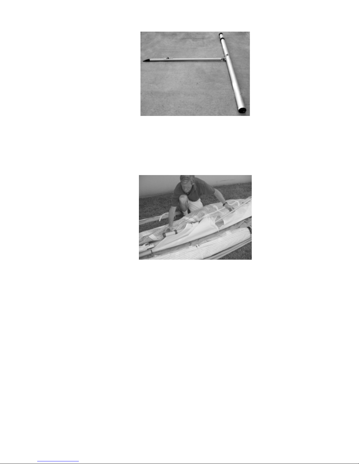
2. Identify the rear leading edges as to left and right in order to make sure you are mounting the
correct rear leading edge into the correct front. Check the “right” / “left” label or marking on the
rear leading edges. If the leading edges are not marked, identify left and right by consideration
of the following: The sprogs are mounted to the back side of the leading edges, the sprog cables
are attached to the top of the leading edges, and the wand receptacle is at the outboard end of the
leading edge. The photo below shows the right rear leading edge, in a right side up orientation.
Each rear leading edge should have one crescent on the front end of the tube, and another six
inches aft of that. There should be a clevis pin and safety ring installed in the front crescent, and a
small, hex socket button screw installed in the rear crescent. The spare parts kit included with the
glider should have a small hex wrench that ts this hex socket button screw. Remove the clevis
pin and safety, and the hex socket button screw from each rear leading edge. Take care to preserve
the position and orientation of each crescent on the leading edge tube.
— 6 —
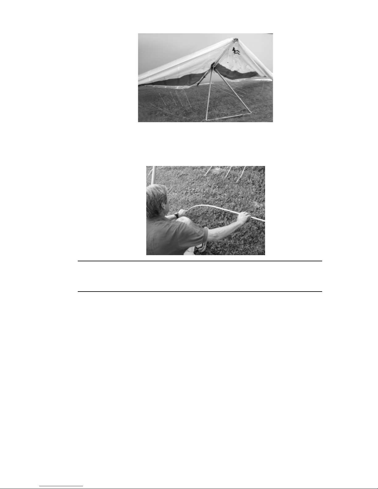
3. Working on one wing at a time, and working with the appropriate rear leading edge, fold the outer
sprog, which is attached to the rear leading edge to the rear against the rear leading edge. Slide
the outboard end of the leading edge tube into the sail through the inboard (front) sprog access
zipper. As the end of the outer sprog reaches the outer sprog access zipper, bring the sprog outside
of the sail through that opening as shown. (The photo below shows the right rear leading edge
being inserted into the sail as described.)
Then slide the rear leading edge forward, allowing the sprog end to remain outside the sail, until
the front end of the rear leading edge is at the aft end of the front leading edge. Carefully align
the rear leading edge with the front leading edge, using the clevis pin hole in the front crescent
and the corresponding hole in the front leading edge as an alignment guide, so that you can slide
the rear leading edge into the front without twisting. Carefully slide the rear leading edge into the
front leading edge until the clevis pin hole in the crescent appears through the corresponding hole
in the front leading edge. (Just prior to this point, if the rear crescent has remained in position
on the rear leading edge, you will need to insert the rear crescent into the front leading edge.)
Install the clevis pin from the bottom of the front leading edge, and install the safety ring on top
of the leading edge. (Make sure at this point that the clevis pin passes through all three parts; the
front leading edge, the rear leading edge tube and the front crescent. If the clevis pin is properly
installed in all three, you should not be able to pull the rear leading edge out of the front leading
edge, and the rear leading edge should be secure and tight in the front leading edge – i.e. you
should not be able to wiggle it up and down at the forward end.) At this point, if the rear crescent
has not moved, the threaded insert in the rear crescent should be visible through, and centered in
the forward most of the three holes in the front leading edge. Install the hex socket button screw
to secure the crescent in place. (See the photo below showing the clevis pin, safety ring and
button screw correctly installed in the right leading edge.) Repeat the process for the other leading
edge.
— 7 —
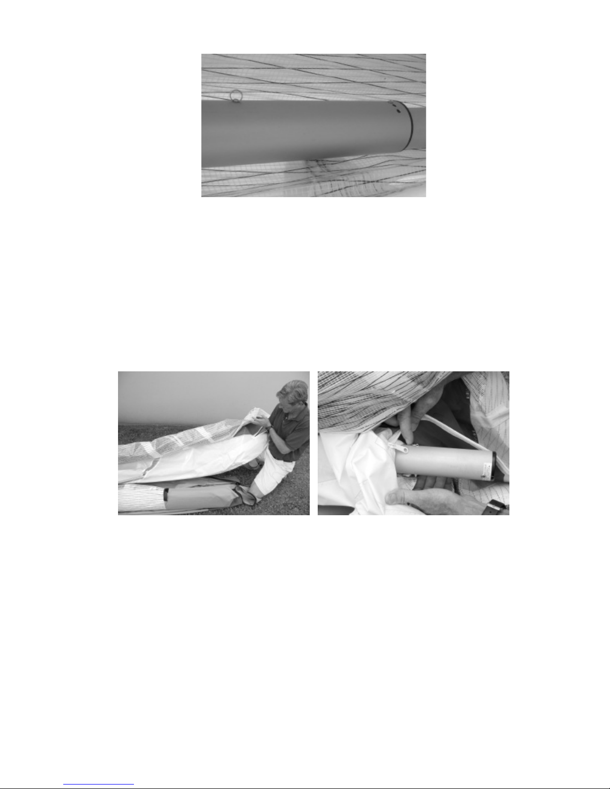
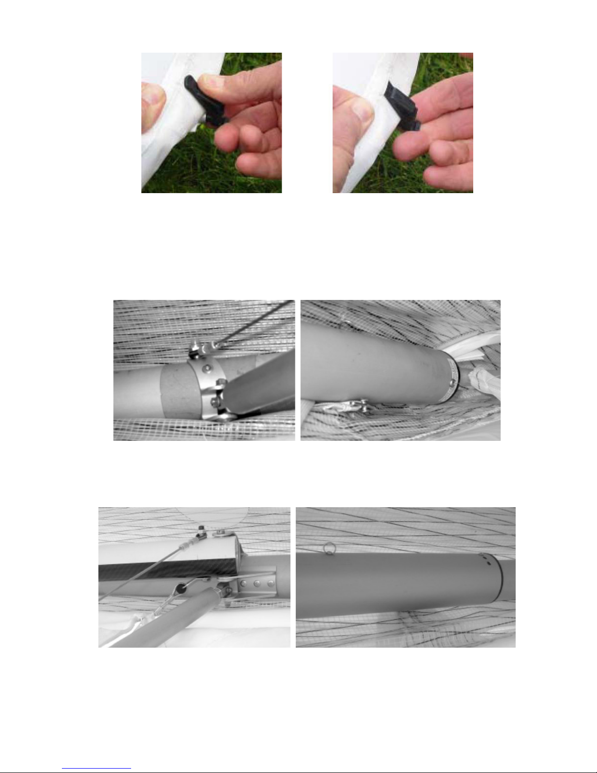
5. Unzip the tip access zipper and pivot the cam lever outside of the sail. Reach into the sail from
the cam lever access opening and grasp the rear end of the rear leading edge. Work the sail
forward over the rear leading edge until the last six inches of the leading edge is outside the cam
lever access zipper.Find the sail mount strap and stretch it towards the rear of the leading edge. If
necessary, you can provide additional slack in the sail by disconnecting the sail mount at the nose
of the glider by removing the screws that secure the nose mount webbing to the leading edge.
Position the rear sail mount strap on the bottom of the leading edge tube and make sure the strap
is not twisted or wrapped around the tube. Remove the safety ring from the clevis pin located ve
inches from end of the leading edge, remove the clevis pin, and pass it through the tang in the sail
mount webbing. Re-install the clevis pin in the leading edge, from the bottom, and re-install the
safety ring on the clevis pin on top of the leading edge. See the photos below.
6. Verify that the sail mount strap is on the bottom of the rear leading edge, is not twisted, and is not
wrapped around the leading edge tube. Re-mount the sail at the nose. Pull the sail back over the
end of the leading edge. (Note, if you are unable to remount the sail at the nose at this time, you
can wait until you set up the glider and spread the wings. However, anytime you spread the wings
without the sail mounted at the nose you must be careful to insure that the sail slides forward as
you spread the wings, otherwise you could tear open the sail at the nose.)
7. Fold the outboard sprog to the front and against the leading edge. Place a Velcro around the sail at
this point.
Rotate the tip wand cam lever inside the sail and close the Velcro closure or access zipper. Fold
the tip of the sail over, roll it up and re-install the tip bags. Flip the glider onto its back, put the
glider bag back on and zip it up.
— 8 —
To remove the rear leading edges for shipping follow these steps
This process will basically be the reverse of installing the rear leading edges after shipping. Before
beginning, read through the section above on how to re-install the rear leading edges. While following
the instructions below, refer to the photos in the section above for reference, if necessary.
1. Lay the glider on the ground or oor, unzip the bag and remove the Velcro ties. Remove the tip
bags and lay the tips out at. The sprog access zippers should be fully unzipped.
2. Unzip the access zipper at the wing tip and rotate the tip wand cam lever outside the bottom
surface. Reach into the sail from the cam lever access opening and grasp the end of the leading
edge tube. Work the sail up over the end of the leading edge to expose the clevis pin that secures
the sail mount strap to the leading edge. Remove the safety ring from the sail mount clevis pin
and remove the pin from the leading edge and from the tang on the sail mount strap. Immediately
re-install the clevis pin in the leading edge tube and re-install the safety ring.
3. Check to see that the rear leading edges are labeled “Left” and “Right.” If they are not, mark them
with an indelible marker.
4. Working through the inboard (front) sprog access zipper, remove the clevis pin and safety that
secures the front crescent and front end of the rear leading edge in place. Also remove the hex
socket button screw that secures the rear crescent reducer in place.
Pull straight aft on the rear leading edge to disengage it from the front. The rear leading edge
should come out of the front with both crescents still in position. Re-install the clevis pin and
safety in the front end of the rear leading edge, securing the crescent to the tube, and reinstall the
hex socket button screw in the rear crescent. Fold the outer sprog towards the rear, and remove
the rear leading edge from the sail through the inboard (front) sprog access zipper.
5. Tape or pad the sprog ends, sprog / leading edge junctions, sprog wire junctions, the front end of
the rear leading edge tubes, and the rear of the front leading edge tubes to prevent sail damage
during transit.
6. Pivot the tip wand cam lever into the opening in the sail and close the access zipper. Carefully
fold the rear of the sail over against the front, and replace the bag on the glider.
— 9 —
T2 Set-Up Procedure
A number of set up operations are made easier by the use of the T2 Set-Up Tool - a six-inch length of 3/4”
tubing included with your glider.
1. Lay the glider on the ground, with the bag zipper up, with the bag at right angles to the wind.
2. Undo the zipper, remove the battens, and remove the control bar bag.
3. Lift and deploy the control bar legs.
a. Remove the ball lock pins from the downtube end ttings.
b. Align the downtube bottom plugs properly in the basetube corner ttings.
c. Install ball lock pins, securing the brackets to the basetube.
Make sure that the small bushings that secure the side wire tangs in the downtube end ttings are
in place, and that the side wire tangs are properly secured. Also make sure that the ball lock pins
are fully and securely engaged in the basetube end brackets.
4. Flip the glider upright on the control bar. Try to set the basetube on level ground. Remove the
glider bag and all the Velcro sail ties. Do not remove the leading edge tip protector bags at this
time. Install the root battens onto the studs on top of the keel at this time.
Spread the wings almost all the way. As you spread the wings, and before you make any attempt
to tension the crossbar, verify that the bottom side wires are not wrapped around or tangled in the
inboard sprog.
— 10 —
6. Remove the battens from the batten bag, and check each batten for symmetry against the
corresponding batten from the other wing. Align the battens at the nose, and at about the 60%
chord point as shown. There should not be any deviation of more than 1/8” from one to the other
along the full length of the battens.
Wills Wing convention is that black tipped battens go in the right wing and white tipped
battens in the left. Battens are numbered from the tip inwards, and the shortest top
surface cambered batten in a T2 is designated as the “#2” batten.
Working from the root out, install the three longest cambered top surface battens in the sail. Do
not engage the tips in the trailing edge at this time.
Insert the battens carefully, so as to minimize stress and wear on the sail. Never insert or remove
the inboard most top surface battens with the crossbar tensioned and never insert or remove
battens with heavy wind pressure on the top of the sail or in any condition which causes the
battens to slide with great resistance in the pockets.
If you choose not to check your battens for symmetry before each ight, you should, at a
minimum check them every few ights.
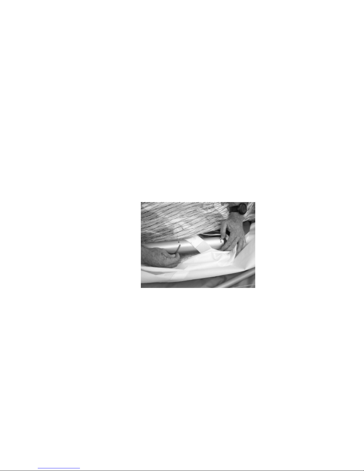
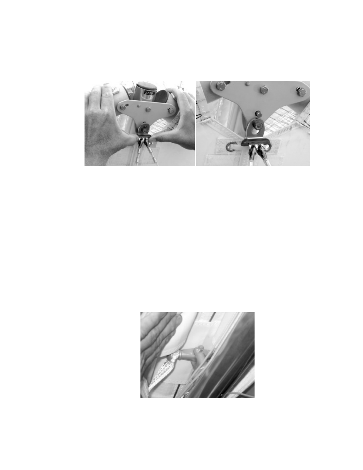
7. Spread the wings all the way and check all cables for any twisted thimbles or tangled cables. At
the rear of the keel, reach inside the keel pocket and nd the sweep wire. Pull the sweep wire out
the rear end of the keel pocket, and check that it is not wrapped around the keel. Insert the T2
Set-Up Tool in the string loop on the keyhole tang and tension the crossbar by pulling back on the
sweep wire. Secure the sweep wire by installing the keyhole tang onto the keyhole collar on the
rear wire bolt. Make sure the tang slides fully forward in the slot on the collar so that the narrow
part of the keyhole slot is fully captive in the narrow part of the bolt collar.
— 11 —
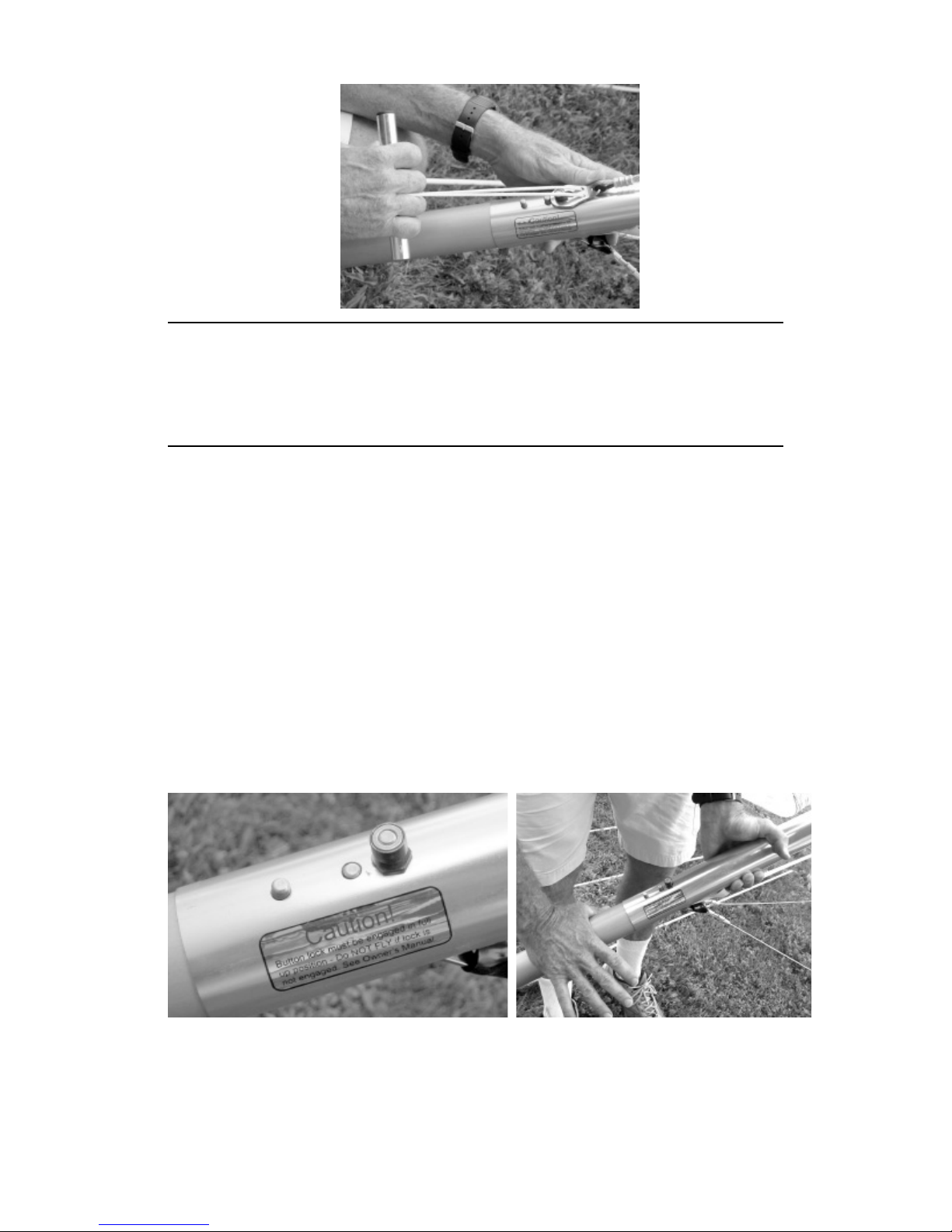
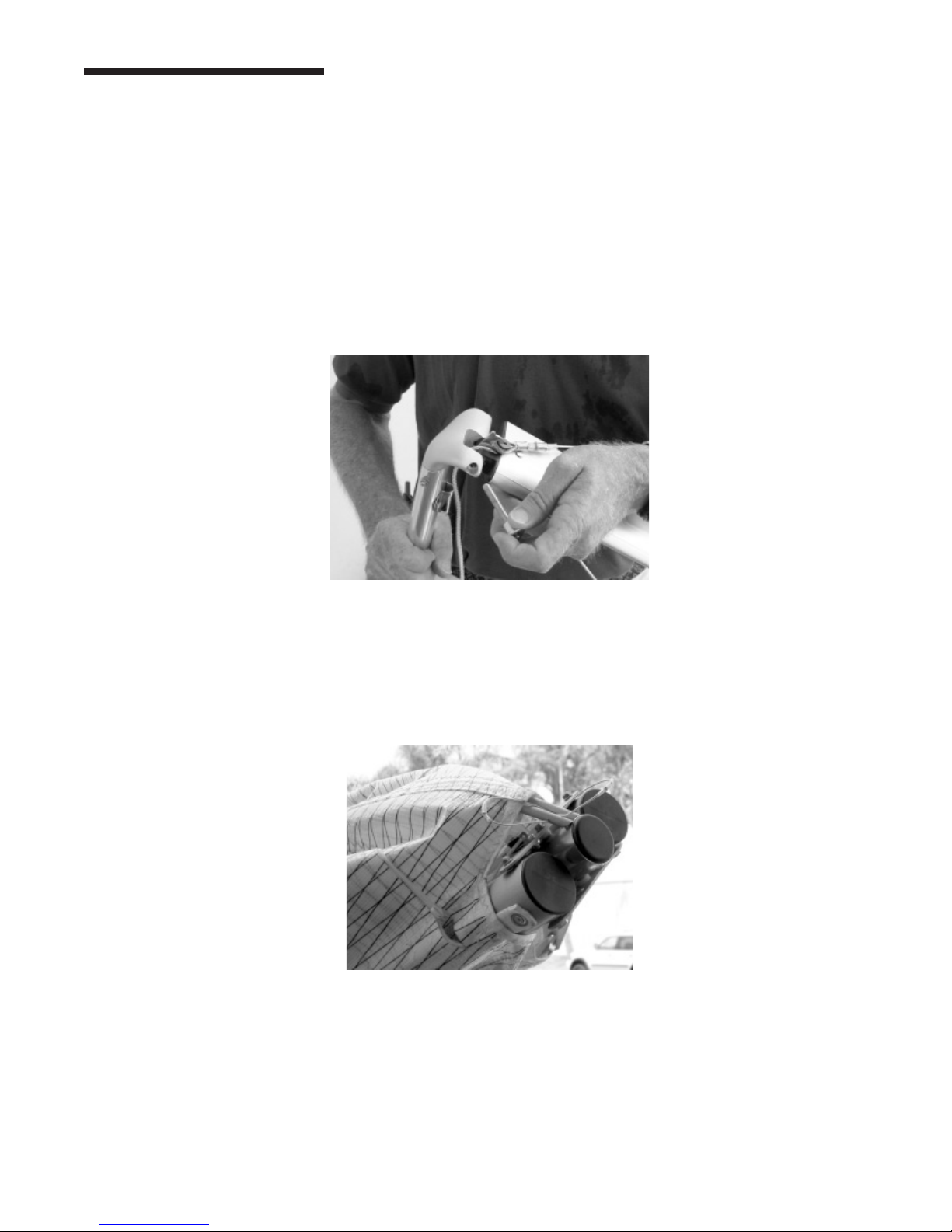
Make sure at this time that the button lock safety is in the full up, engaged position. On
the T2, it is ABSOLUTELY NECESSARY that the sweep wire button lock safety be fully
functioning and fully engaged whenever the sweep wire is attached – it is a NO FLY
condition if the button lock becomes stuck in the down position such that it is does not
properly prevent the sweep wire from becoming detached from the collar.
The reason that this is so critically important on the T2 is that if the VG is pulled on and then
released on the ground, the crossbar will likely not fully return to its full forward position, leaving
the sweep wire slack, and allowing the sweep wire tang to disengage from the keyhole collar if
the safety is not engaged. In ight, there is enough load on the crossbar to maintain continuous
tension on the sweep wire, but on the ground, cycling the VG can cause the sweep wire to become
slack. Never install the keyhole tang onto the keyhole bolt without making absolutely sure
that the tang is fully engaged on the narrow neck of the bolt, and pulled forward into the fully
locked position with the safety button in the full up position. Due to the friction in the system,
if this attachment were to become disengaged on the ground, it could be possible that the pilot
would not notice it, and he could launch with the sweep wire disengaged. This would result in a
complete loss of structural support of the glider and a total loss of control. Also, never attach the
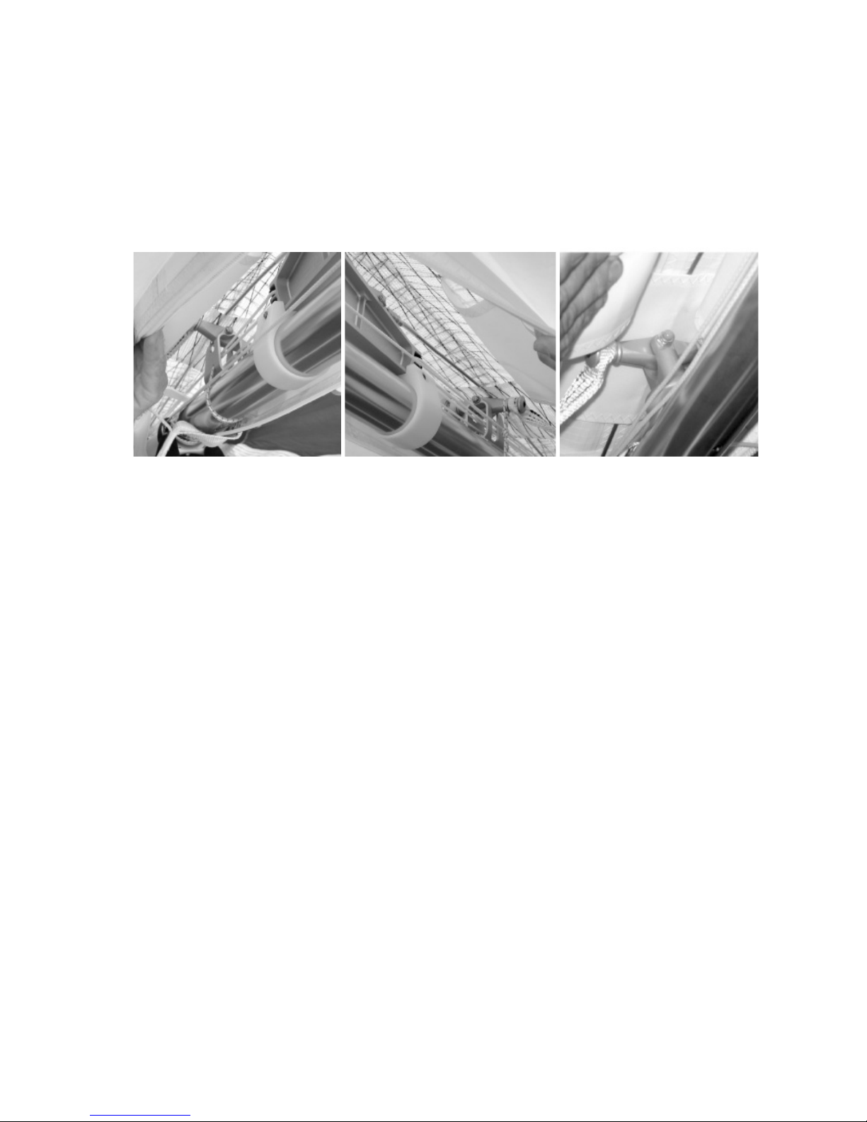
pull string to the collar, even temporarily. (Note, if the button should become stuck in the down
position, it can usually be released and made to pop up by lifting on the keel tube just forward of
the keyhole collar bolt, and taking the ground load off of the rear stinger. See the photos below.)
— 12 —
Note: T2s manufactured during or after September 2005 include a keel stand. After you have tensioned the sweep wire, if you are setting up on reasonably level ground, and if there is not too much
wind, you can deploy the keel stand as shown below to raise the trailing edge of the glider. This will
keep the tips off the ground and make installation of the remaining battens easier.
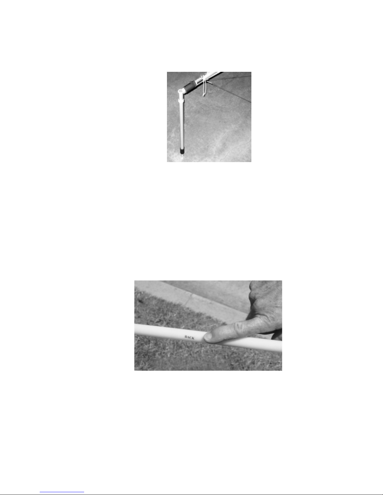
8. The next step is to install the tip wands. Remove the wingtip protector bag. Unfold the tip of the
sail and open the zipper closure that provides access to the tip wand cam lever. Rotate the cam
lever outside the sail. The tip wands are tapered; the larger end is installed in the receptacle in the
end of the leading edge tube. Near the outboard end of the wand is a label that reads “BACK.”
This indicates the side of the tip wand that should be positioned towards the rear of the glider
after the wand is inserted in the leading edge, and before the cam lever and cup are installed.
Reach into the opening with the tip wand in your hand and work your way up to the end of the
leading edge. Install the tip wand into the receptacle, and push it all the way in until it bottoms
out. Rotate the wand to align the “back” label to the rear – away from the front of the leading
edge. (Note: The purpose of aligning the wand in this way is to extend the service life of the wand
– see Wills Wing Technical Bulletin TB20040424 – available at www.willswing.com for more
information.)
9. Working from the front side of the leading edge, facing the glider, hold the end of the leading
edge tube from underneath in one hand and grasp the wand lever and cup in the other hand. Place
the open end of the wand cup against the front side of the tip wand. While supporting the leading
edge tube by pulling it towards you, push back against the wand with the wand cup, allowing
the cup to slide outwards along the wand as the wand bows back. (Keep in mind here that you
are not trying to “stretch” the sail lengthwise along the wand – that won’t work. You are bowing
the wand back by pressing the cup against the front, which will naturally pull the sail outwards
around the bow of the wand as you do so. Also keep in mind that the wand must be allowed to
bow in order for this to work; you cannot be holding onto the wand with your other hand during
— 13 —
this operation.) As the wand cup reaches the end of the wand, it will rotate and pop into place
over the end of the wand.
Note: There are two other methods that can be used to install the wand cup onto the wand if
you’re having difculty with this method. One is to use the same procedure as described above,
but to follow the procedure before tensioning the crossbar. The other is to install the wands and
wand cups before installing any battens or tensioning the crossbar. To do this, install the wand
into the wand receptacle as described above. Then, grasp the wand in one hand and the cam lever
in the other hand.
Pull straight back on the cam lever until the cup is beyond the end of the wand, and then install
the cup onto the wand. Either of these methods is an acceptable alternative to the primary method
described above, and you may nd either or both to be easier. The disadvantage of either is that
because the crossbar is not tensioned, the wing tips are not being held up off the ground, so the tip
area of the sail is more exposed to dirt and wear.
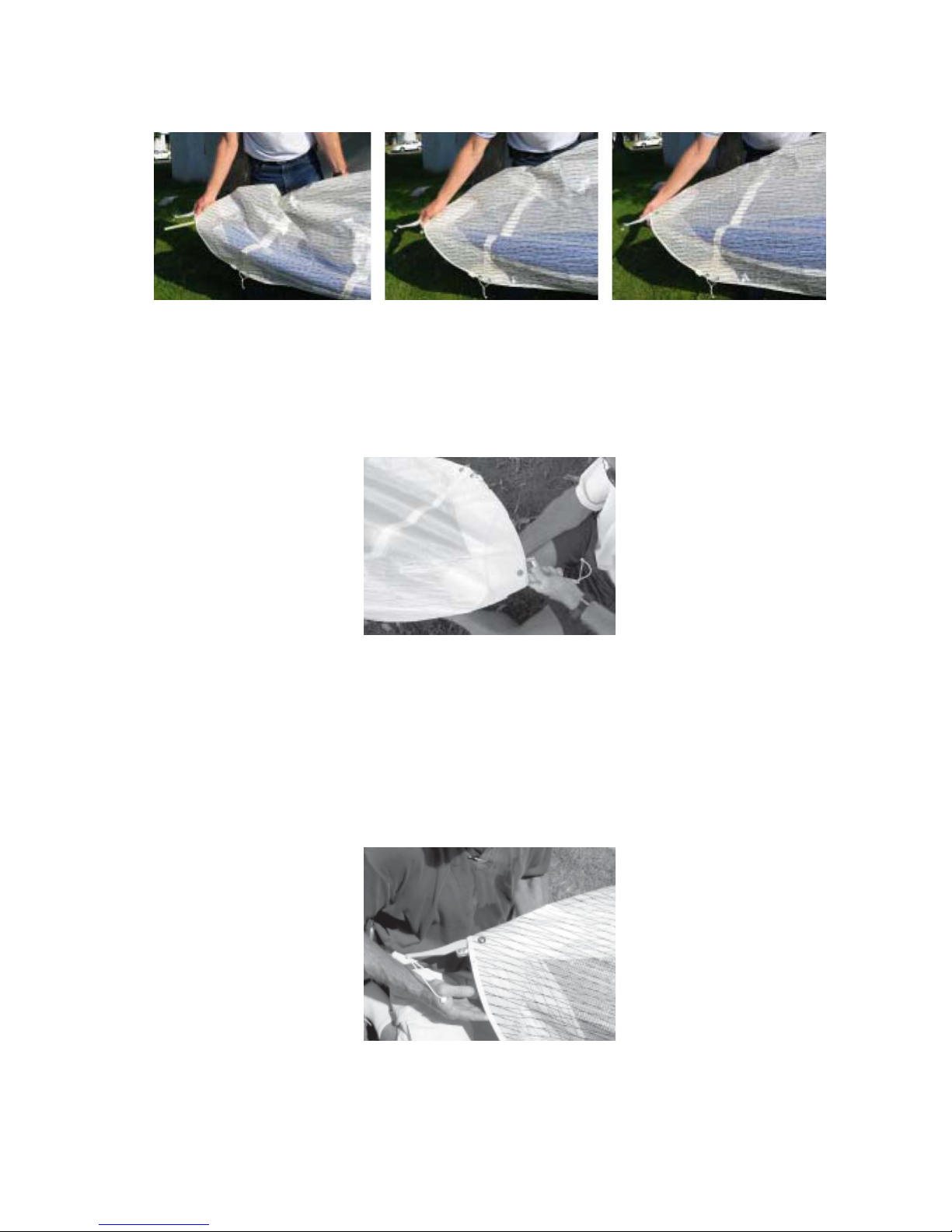
10. The next step is to cam over the tip wand cam lever, tensioning the sail at the tip. Tension the
crossbar haulback cable if you have not done so already. Hook your thumb into the loop of string
on the cam lever and grasp the opening of the sail in the bottom surface with your other hand.
11. Pull the string around in a circular motion, rst towards the trailing edge and then inboards
towards the keel, to cam the wand lever over and tension the wand. Before you zip up the access
zipper, look into the sail from the tip and verify that the most outboard internal rib is fully zipped
up, and that the “back” label on the wand is properly aligned – it should now be aligned with the
— 14 —
portion of the cam lever that is resting against the wand. Then close the access opening.
12. Install the remaining outboard top surface battens. Secure the shortest cambered battens with
a double purchase loop of the 205 leech line. At this time you can install the batten tips for the
cambered battens into the hem of the trailing edge using the following procedures. The lever
tip incorporates a hinge and a snap locking mechanism, as well as a threaded shank that allows
for adjustment of the overall batten length, and hence the chordwise tension that the batten puts
on the sail. The locking mechanism can be broken if it is not released properly before the lever
portion of the tip is rotated upwards. If it does break, it will usually break at the locking hook on
the lever (rear) portion of the tip. Also the hinge portion can pop apart relatively easily. (This is
not a failure of the tip, and you can easily pop the hinge back together again.)
If you do have a failure of the locking hook on the lever portion, simply pop the hinge apart and
pop on a new lever part. It is also possible, though less likely, to break the forward portion of the
tip. If that happens, unthread the tip from the batten and thread in a new piece.
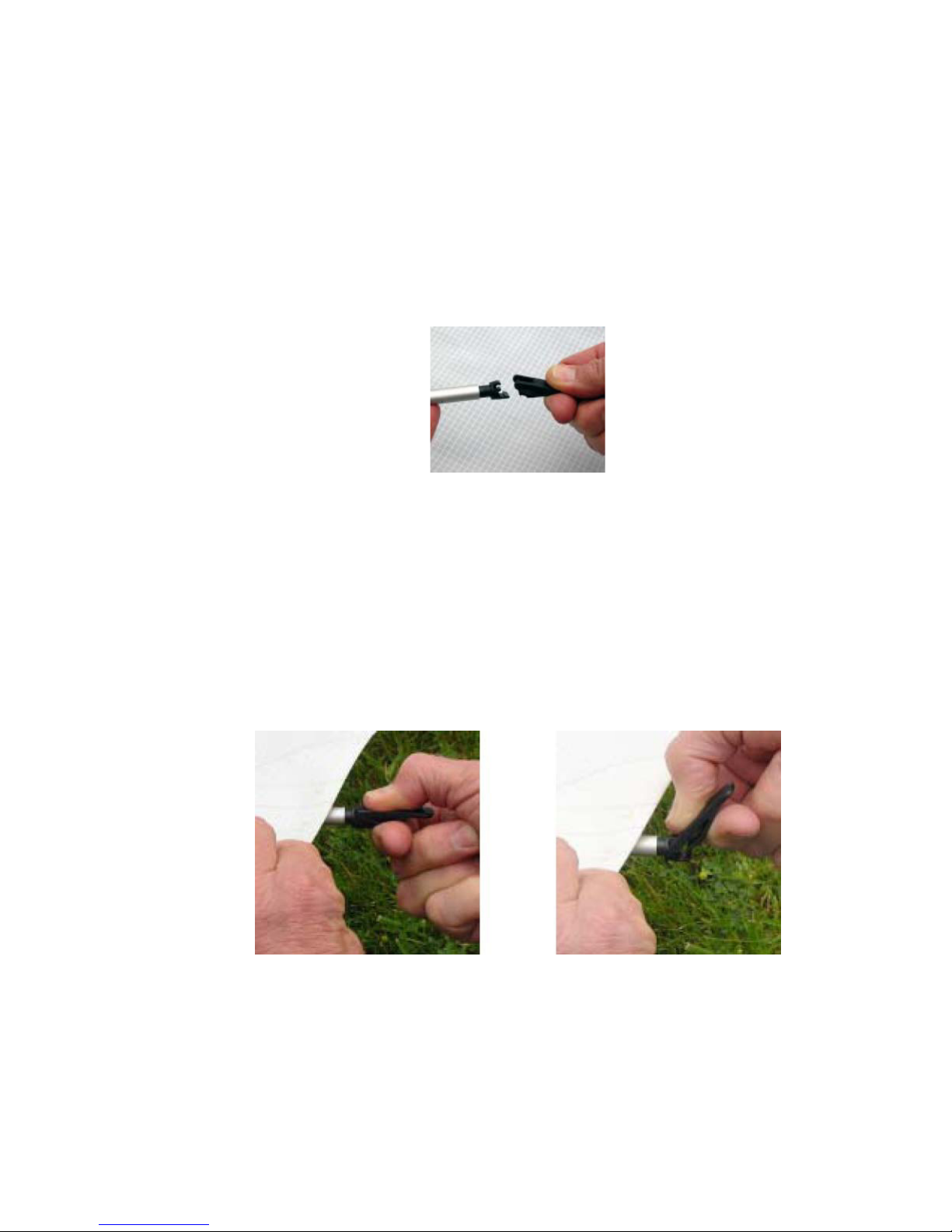
Once the batten is installed, in order to t the batten tip into the trailing edge hem, you will need
to unlock the lever part of the tip and pivot it upwards. To unlock the tip, place a slight downward
pressure on the top of the lever portion of the tip, and squeeze upwards on the bottom of the lever
portion just behind the locking clasp. Then pivot the lever tip upwards. You should not feel any
resistance to the lever rotating upwards - if you do you haven’t properly released the locking
portion. If you hear a click when pivoting the lever upwards, it is likely that you have broken, or
partly failed the locking tab on the lever.
After the rear of the tip has been rotated upwards, t it into the gap in the hem of the trailing edge
and then rotate the tip downwards until it locks into place. You should hear a click at this point,
and the tip should be securely held in the locked position. (Note: A tip with a failed catch will
still “click” when you rotate the lever downwards into position, but depending on the degree of
failure of the catch, it may not support an upward load on the trailing edge sufcient to keep the
tip locked in position.) NOTE: The root battens (the ones you installed onto the keel studs at the
beginning of the set-up process) on the T2 extend all the way to the trailing edge, and are also
tted with lever tips. Don’t forget to engage these into the trailing edge hem at this time.
— 15 —
13. The next step is to deploy the sprogs and secure them in position. Before doing so, working
through the sprog access zippers, preight the following items:
a. The remaining internal ribs to conrm that they are fully zipped up.
b. The sprog hardware, including the leading edge sprog brackets, the attachment of the sprogs
to these brackets, and the sprog cable attachments at both ends of each sprog cable.
c. The rear leading edge sail attachment / tip wand installation.
d. The leading edge crossbar junction hardware, including the bolt and nut that secures the
bottom side wire and inboard sprog wire to the crossbar, and the bolts and nuts that attach the
inboard sprog and crossbar to the leading edge. Also preight the rear leading edge / front
leading edge junction at this time
To deploy and secure each sprog, swing the sprog away from the leading edge and align it in the
center of the rear end of the sprog access zipper, such that the rear end sprog paddle lies below
both the transverse batten and the short piece of webbing in the sail. Fully close the sprog access
zipper and this will secure the sprog in the proper position underneath the transverse batten and
— 16 —
capture it in position with the webbing.
14. Attach the bottom front wires to the bottom of the noseplate. Install the keyhole tang over the
collared bolt by pulling down on the nose of the glider while pressing the tang upwards over
the collared bolt. Remember, it is the pulling down of the glider’s nose rather than the upward
pressure on the tang that allows you to install the tang over the bolt.
After installing the keyhole tang, verify that it has been secured in position by the button lock make sure that the button pops up in front of the tang to lock the tang in position after the tang is
fully seated on the collar.
Note that on the T2, there is not as much tension in the bottom wires to keep the keyhole tang
engaged as there would be on a glider with top rigging. Because of the lack of a kingpost and
top rigging on the T2 design, tethering the glider by the nose, such as is sometimes done after
setup and while waiting to y, creates the potential for overloading the keel tube of the glider
which could result in a structural failure. A similar problem could arise during a hang check. To
avoid overloading the keel, any tether line attached to the nose, or any restraint used during a
hang check should pull as much as possible in line with the keel, and in no case in a direction
more than 45 degrees below the line of the keel tube itself. See the diagram in the section on
towing. Alternately, for performing a hang check, the glider can be supported by pushing up from
underneath the rear keel instead of pulling down and forward at the nose.
16. Unzip the center zipper. On later model T2’s, rotate the hang system base pillar to align the hang
lever at right angles to the keel tube. (See photo)
— 17 —
17. With the center zipper open, look inside the sail to preight the following items, including all
nuts, bolts, pins and safeties:
a. The spar center section, including the front spar hold down strap, and the rear spar anchor.
b. The routing of the VG line.
c. Each spar along its entire length.
d. The top to bottom surface sail velcro attachments.
e. The hang lever and main and backup hang loops.
18. Check the operation of the VG throughout the range, and leave the VG set full tight. Zip up the
center sail zipper
— 18 —

19. Install the nosecone as follows - t the nose cone to the nose of the sail and stretch the top rear
end of the nose cone back along the centerline of the glider. Press down to attach the velcro.
Then pull the bottom front end of the nose cone tight around the bottom of the nose and attach
the velcro. Finally, re-adjust the top rear attachment as necessary to remove any gaps between the
nosecone and the sail along the sides of the nosecone.
Note: T2’s made after June of 2006 feature a nosecone that is attached to the sail at the top rear
end. To install, simply pull the bottom of the nosecone tightly around the nose of the glider and
mate the velcro surfaces at the bottom such that the nosecone lies at and smooth.
It is important to t the nosecone carefully so that there are minimal discontinuities in the
sail in the nose area. Any discontinuity in the sail in the nose area, or along the leading
edge will tend to promote premature separation of the airow, leading to an increased
stall speed and reduced performance.
Never y without the nosecone, or with any replacement that was not designed for your
sail.
20. Return the VG to the full loose position. Open the bottom surface zipper and pull forward on the
crossbar center to assist the crossbar in returning to the full forward position. Then re-close the
center zipper.
21. Install the bottom surface battens. The bottom surface battens are retained by a narrowing at the
front of the bottom surface batten pockets. You will feel increased resistance as you push the
battens into this area.
22. Conduct a complete preight of the glider, checking all assemblies, which have not already been
checked.
— 19 —
 Loading...