

Wills Wing Fusion 141, Fusion 150 Owner's Service Manual
Fusion 141 and 150
Owner / Service Manual
October 15, 1998 - Third Edition

Fusion 141 and 150
Owner / Service Manual
Copyright © 1994, 1995, 1996, 1997, 1998 by Sport Kites, Inc. dba Wills Wing, Inc. All rights reserved.
No part of this manual may be reproduced in any form without the express written permission of
Sport Kites, Inc., dba Wills Wing, Inc.
October 15, 1998 - Third Edition
500 West Blueridge Ave • Orange, CA • 92865 • Phone (714) 998-6359 • FAX (714) 998-0647
Internet Web address: http://www.willswing.com • E-mail: comments@willswing.com

Contents
Glider Delivery Check List.................................................................................... i
Introduction...................................................................................................... 1
Disclaimer and Warning ...................................................................................... 2
Technical Information and Placarded Operating Limitations ...................................... 3
FUSION MANUAL ADDENDUM ........................................................................... 6
Leading Edge Pocket / Mylar Insert ................................................................................... 6
Nosecone Installation ......................................................................................................... 6
Transverse Batten Installation ............................................................................................ 6
Button Lock Apex Slider .................................................................................................... 6
Fusion Breakdown Procedure for Shipping, and Reassembly Procedure ..................... 7
To break down the leading edges follow these steps .......................................................... 7
Remounting the rear leading edges..................................................................................... 8
Fusion Set-Up Procedure .................................................................................... 9
Preflight Procedure .......................................................................................... 15
Along the left leading edge............................................................................................... 15
At the left wingtip ............................................................................................................. 15
Along the trailing edge, left wing ..................................................................................... 15
From the rear keel ............................................................................................................. 16
Along the trailing edge, right wing ................................................................................... 16
At the right tip................................................................................................................... 16
Along the right leading edge............................................................................................. 16
Under the glider at the control bar .................................................................................... 16
Laying the Glider Down Flat .............................................................................. 18
Setting the Glider Up Flat on the Ground ............................................................ 18
Launching and Flying the Fusion........................................................................ 19
Minimum controllable airspeed and minimum sink airspeed .......................................... 19
Using wing tufts to find the minimum sink speed of your glider ..................................... 20
Towing .............................................................................................................................. 22
Trimming Your Glider in Pitch ............................................................................ 23
Speeds to Fly and Using Your Airspeed Indicator ................................................. 24
Using the VG System ...................................................................................... 25
Landing the Fusion .......................................................................................... 26
Fusion Breakdown ........................................................................................... 29
Fusion Stability Systems .................................................................................. 30
Fusion Sprog Adjustment and Flight Testing ........................................................ 31
Sprog measurement .......................................................................................................... 31
Alternate sprog measurement ........................................................................................... 31
Method of adjustment ....................................................................................................... 31
Test flight .......................................................................................................................... 32

Maintenance................................................................................................... 33
Every month...................................................................................................................... 33
Every six months .............................................................................................................. 33
Every year ......................................................................................................................... 34
Special circumstances....................................................................................................... 34
A note about cables and cable maintenance ..................................................................... 35
Removing the Sail from the Airframe and Re-Installing.......................................... 36
Sail removal ...................................................................................................................... 36
Re-installing the sail on the frame .................................................................................... 37
Replacing the Perlon hang loop ........................................................................................ 38
Glider Tuning .................................................................................................. 39
Dismounting and remounting the sail at the tip................................................................ 39
CG adjustment .................................................................................................................. 39
Turn trim........................................................................................................................... 39
Airframe............................................................................................................................ 39
Battens .............................................................................................................................. 39
Sail mount plugs - adjusting sail tension and rotational alignment .................................. 39
Sail tension ....................................................................................................................... 40
Twisting a tip .................................................................................................................... 40
Batten tension ................................................................................................................... 40
Leading edge sail tension.................................................................................................. 41
Car Top Mounting and Transport ........................................................................ 41
In Closing....................................................................................................... 41
HGMA Fusion 150 COMPLIANCE VERIFICATION SPECIFICATION SHEET ...............................42
HGMA Fusion 141 COMPLIANCE VERIFICATION SPECIFICATION SHEET ...............................43
Assembly Diagrams
83E01.1 Fusion Crossbar Center ....................................................................... 2
83E02.2 Fusion Front Leading Edge and Cam VG ................................................ 3
83E03.2 Fusion Sprog Wire and Bracket (Carbon Sprog) ...................................... 4
83E07.0 Fusion Sprog (Carbon) ........................................................................ 5
83E04.1 Fusion Noseplate ............................................................................... 6
83E05.1 Fusion Rear Leading Edge.................................................................... 7
83E06.1 Fusion Keel ....................................................................................... 8
83E10.0 Fusion Aluminum Sprog and hardware Assembly.................................... 9
83E09 VG Folding Base Tube ....................................................................... 10
80E08 VG Control Bar ................................................................................ 11
Fusion 150 Frame Plans ................................................................................... 12
Fusion 141 Frame Plans ................................................................................... 13
Button Lock Apex Slider Assembly .................................................................... 14
Fusion Control Bar........................................................................................... 15

World Record Hang Gliders Since 1973 • Orange, California USA
Glider Delivery Check List
PO # Model / Size Serial # Date
Customer Name Phone #
Address City State Zip
Dealership Name Order Date Date Delivered
Dealer Test Flight Results
Pilot Site Date Tested Airtime
Test Flight Comments
Dealer/ Customer Checklist Customer Dealer
Reviewed glider owner’s manual with customer
Reviewed set-up, break-down, and pre-flight procedures
Reviewed maintenance and service procedures
Reviewed car top mounting (HG), Trunk heat cautions (PG)
Delivered customer response form
Delivered glider parts kit
Delivered owner’s manual
READ BEFORE FLIGHT
CAUTION: Use of this equipment may result in INJURY OR DEATH. Please be sure
you are qualified to fly this product, are thoroughly familiar with and follow all
proper procedures as explained in the owner’s manual. You are reminded that YOU
FLY AT YOUR OWN RISK.
I have read and understood all of the above and hereby release Wills Wing Inc., its
employees, and dealers acting in association with or on behalf of Wills Wing Inc.
from all liability in connection with my use of this glider.
Customer Signature Dealer Signature
Wills Wing Inc. • 500 West Blueridge • Orange, California USA • 92865 • Ph(714) 998-6359


Introduction
Thank you for purchasing a Wills Wing glider, and welcome to the world wide family of Wills Wing
pilots. We are a company of pilots and aviation enthusiasts, and our goal is to serve your flying needs
now and in the future, as we have done for pilots throughout the world since 1973.
We encourage you to read this manual thoroughly for information on the proper use and maintenance
of your Wills Wing glider. If at any time you have questions about your glider, or about any aspect of
hang gliding that your Wills Wing dealer cannot answer, please feel free to give us a call.
If you have access to the Internet, please visit us regularly at http://www.willswing.com. The site
features extensive information about Wills Wing gliders and products, a Wills Wing Dealer directory, a
comprehensive list of service and technical bulletins, the latest editions of owners manuals, our complete retail price list, a search engine, e-mail and more.
The most important contents of our internet site are the service and technical bulletins, and the latest
editions of owners manuals. This is your single best source for safety and airworthiness advisories on
Wills Wing products. Many of the documents are published in Adobe Acrobat format. A free viewer for
Acrobat files is available at http://www.adobe.com.
We wish you a safe and enjoyable flying career, and, once again, welcome aboard!
Rob Kells, Mike Meier, Linda Meier, and Steve Pearson
Wills Wing, Inc.
1

Disclaimer and Warning
Hang gliding is a form of aviation. Like any form of aviation, its safe practice demands the consistent
exercise of pilot skill, knowledge of airmanship and weather, judgment and attention at a level which is
appropriate to the demands of each individual situation. Pilots who do not possess or exercise the
required knowledge, skills and judgment are frequently injured and killed. The statistical rate at which
fatalities occur in hang gliding is approximately one per thousand participants per year.
The Federal Aviation Administration does not require a pilots license to operate a hang glider. Hang
gliders and hang gliding equipment are not designed, manufactured, tested or certified to any state or
federal government airworthiness standards or requirements. Federal Aviation Regulation Part 103
states in part, "ultralight vehicles are not required meet the airworthiness certification standards
specified for aircraft or to have certificates of airworthiness" and "operators of ultralight vehicles are
not required to meet any aeronautical knowledge, age, or experience requirements to operate those
vehicles or to have airman or medical certificates." Wills Wing hang gliding products are not covered
by product liability insurance. As a hang glider pilot, you are entirely responsible for your own safety.
You should never attempt to fly a hang glider without having received competent instruction. We
strongly recommend that you not participate in hang gliding unless you recognize fully and wish to
personally assume all of the associated risks.
Please fly safely.
2

Technical Information and Placarded Operating Limitations
The Fusion 141 and 150 have been tested and found to comply with the Hang Glider Manufacturers
Association (HGMA) Airworthiness Standards. These standards require:
1. A positive load test at root stall angle of attack at a speed equal to at least the greatest of:
a. 141% of the placarded maximum maneuvering speed
b. 141% of the placarded maximum rough air speed
c. 123% of the placarded speed never to exceed
for at least three seconds without failure.
The required speed for the Fusion for this test was 65 m.p.h..
2. A negative 30 degree angle of attack load test at a speed equal to at least the greatest of:
a. 100% of the placarded maximum maneuvering speed
b. 100% of the placarded maximum rough air speed
c. 87% of the placarded speed never to exceed
for at least 3 seconds without failure.
The required speed for the Fusion for this test was 46 m.p.h..
3. A negative 150 degree angle of attack load test at a speed equal to at least the greater of 30 m.p.h.
or 50% of the required positive load test speed for at least 3 seconds without failure.
The required speed for the Fusion for this test was 32 m.p.h..
4. For the Fusion with a Vne of 53 m.p.h., pitch tests at speeds of 20 m.p.h., 37 m.p.h. and 53 m.p.h.
which show the glider to be stable over a range of angles of attack from trim angle to 20 degrees
below zero lift angle at 20 m.p.h., and from trim angle to 10 degrees below zero lift angle at 37
m.p.h., and from 10 degrees above zero lift angle to zero lift angle at 53 m.p.h..
5. Flight maneuvers which show the glider to be adequately stable and controllable throughout the
normal range of operation.
Note: The Fusion has been designed for foot launched soaring flight. It has not been designed to be
motorized, tethered, or towed. It can be towed successfully using proper procedures. Pilots wishing to
tow should be USHGA skill rated for towing, and should avail themselves of all available information
on the most current proper and safe towing procedures. Suggested sources for towing information
include the United States Hang Gliding Association and the manufacturer of the towing winch / or
equipment being used. Wills Wing makes no warranty of the suitability of the glider for towing.
Because of the lack of a kingpost and top rigging on the Fusion design, tethering the
glider by the nose, such as is commonly done during platform towing operations, creates
the potential for overloading the keel tube of the glider which could result in a structural
failure. To avoid overloading the keel, any tether line attached to the nose should pull as
much as possible in line with the keel, and in no case in a direction more than 45 degrees
below the line of the keel tube itself. Please read the section on towing.
3

Flight operation of the Fusion should be limited to non aerobatic maneuvers; those in which the pitch
angle will not exceed 30 degrees nose up or nose down from the horizon, and the bank angle will not
exceed 60 degrees. The Fusion is generally resistant to spinning, but may spin from a stalled turn,
especially if the VG is adjusted at or near the tight end of the range, and the rate of application of pitch
is moderately rapid. The Fusion can be induced to spin at any VG setting. Recovery from a spin
requires unstalling of the wing, and it is therefore critically important that in the event of a spin, no
application of nose up pitch control be held. The Fusion will recover from a spin once control pressures
are relaxed. As the nose lowers and the angle of attack is reduced, the stall will be broken and the spin
will stop. However, such recovery will consume significant altitude, and will result in the glider
assuming an unpredictable heading. Recovery from a spin may therefore involve a flight trajectory
which intersects the terrain at a high rate of speed. An aggravated spin could result in loss of control, in
flight inversion, and structural failure. Therefore no attempt should ever be made to deliberately spin
the glider. The Fusion provides the pilot with a high degree of pitch authority, in combination with a
very low twist sail. As a result, it is possible by pushing fully out on the bar to produce a very aggravated and severe stall, the recovery from which may involve very severe pitch down rotation, the pilot
going weightless, and the glider recovering via an unpredictable trajectory with a significant altitude
loss. Therefore, full arms extension aggravated stalls should not be induced except on landing flare.
The maximum steady state speed for a prone pilot in the middle of the recommended weight range full
forward on the control bar with the VG set full tight is approximately 58 m.p.h. for the Fusion. The
placarded speed never to exceed for the Fusion is 53 m.p.h. An airspeed indicator is provided with the
Fusion and should be used by the pilot as an aid to comply with the placarded limitations.
The placarded maximum maneuvering speed, and the placarded maximum rough air speed of the
Fusion are each 46 m.p.h. This speed will be achieved with the control bar basetube approximately at
the waist. This speed should not be exceeded in anything other than smooth air. No abrupt maneuvering
or control inputs should be made at anything above this speed.
The stability, controllability, and structural strength of a properly maintained Fusion have been determined to be adequate for safe operation when the glider is operated within all of the manufacturer
specified limitations. No warranty of adequate stability, controllability, or structural strength is made
or implied for operation outside of these limitations.
The stall speed of the Fusion at maximum recommended wing loading is 25 m.p.h. or less. The top
(steady state) speed at minimum recommended wing loading for a prone pilot with a properly designed
and adjusted harness is at least 45 m.p.h.. All speeds given above are indicated airspeeds, for a properly calibrated airspeed indicator mounted in the vicinity of the pilot. Wills Wing provides such an
airspeed indicator with the glider. It is strongly recommended that the pilot fly with such an airspeed
indicator. Refer to the section on using the airspeed indicator for further information on speeds to fly.
The recommended hook in pilot weight range for the Fusion is:
Fusion 150: 150 - 275 lbs.
Fusion 141: 135 - 235 lbs.
Be advised that pilots with hook in weights of less than 20 lbs above minimum will find the Fusion
more demanding of pilot skill to fly, and that pilots hooking in within 20 lbs of the maximum will
experience some relative degradation of optimum sink rate performance due to their higher wing
loading.
4

A minimum USHGA Advanced (IV) level of pilot proficiency is required to fly the Fusion safely. Pilots
are advised that the optimum proficiency level for the Fusion is higher than the minimum recommended. Operation of the glider by unqualified or under qualified pilots may be dangerous.
Operating the Fusion outside of the above limitations may result in injury and death. Flying the Fusion
in the presence of strong or gusty winds, or turbulence may result in loss of control of the glider which
may lead to injury and death. Do not fly in such conditions unless you realize and wish to personally
assume the associated risks. Wills Wing is well aware that pilots have, and continue to perform maneuvers and fly in conditions which are outside the recommended operating limitations stated herein.
Please be aware that the fact that some pilots have exceeded these limitations in the past without
dangerous incident does not imply or insure that the limitations may be exceeded without risk. We do
know that gliders which meet all current industry standards for airworthiness can and do suffer in flight
structural failures, both as a result of turbulence, and as a result of various maneuvers outside the
placarded operating limitations, including, but not necessarily limited to aerobatics. We do not know,
and cannot know, the full range of maneuvers or conditions which may cause the pilots safety to be
compromised, nor can we test the glider in all possible circumstances.
5

FUSION MANUAL ADDENDUM
There have been several design improvements made to late model Fusions. Please take a moment to
note the following changes before setting up or flying your new Fusion.
Leading Edge Pocket / Mylar Insert
The mylar pocket has been changed to make the removal of the mylar insert easier. On new style
Fusions the mylar pocket is open to the front so the mylar can be removed without disassembling the
glider.
Nosecone Installation
The new style nose cone has no velcro on the back edge. To install the nosecone slide the top rear edges
between the mylar pocket and mylar insert. Work it back into position flush with the back edge of the
mylar pocket, and then velcro the lower edge into place on the bottom surface. It takes a bit of practice
to get it installed cleanly, but you will notice there is no bump caused by the velcro at the back edge.
Transverse Batten Installation
The transverse battens (54 inches long with black heat shrink on the outside) go inside the bottom
surface at the back between the #3 batten (second shortest curved batten) and the #5 batten (fourth
shortest curved batten). The transverse batten does not need to be removed unless the rear leading
edges are removed to short pack the glider for transport. Please refer to page 6 in this manual for
more information on this.
The new style Fusion sail does not have a batten pocket to hold the transverse batten.
The sprog (internal washout strut) supports the transverse batten below the #4 batten.
To install the transverse batten slide the end of the batten through the webbing receptacle just inboard
of the #3 batten, and then slide it through the webbing receptacle at the #5 rib. Put tension on the
batten towards the #5 rib and firmly close the velcro at the #3 receptacle to keep the transverse batten
in place.The transverse batten is tapered at each end. The longest (flat) side of the batten goes down
towards the bottom surface. The newest Fusion transverse battens are labeled TOP on the short side.
Button Lock Apex Slider
Newer Fusions are equipped with a spring loaded control bar apex slider lock. An illustration of the
new assembly is included in the assembly diagrams. This new system is much easier to release and
engage than the clevis pin and safety ring on earlier models.
6

Fusion Breakdown Procedure for Shipping, and Reassembly Procedure
The front leading edge is 60mm (2.36") oversleeved with 62mm (2.44") at the crossbar junction. The
rear leading edge is 50mm (1.97") oversleeved with 52mm (2.05") at the front end. There are two
fittings attached to the front end of the rear leading edge to provide the proper fit and orientation in the
front leading edge. The front fitting is slotted and engages in a clevis pin though the front leading edge.
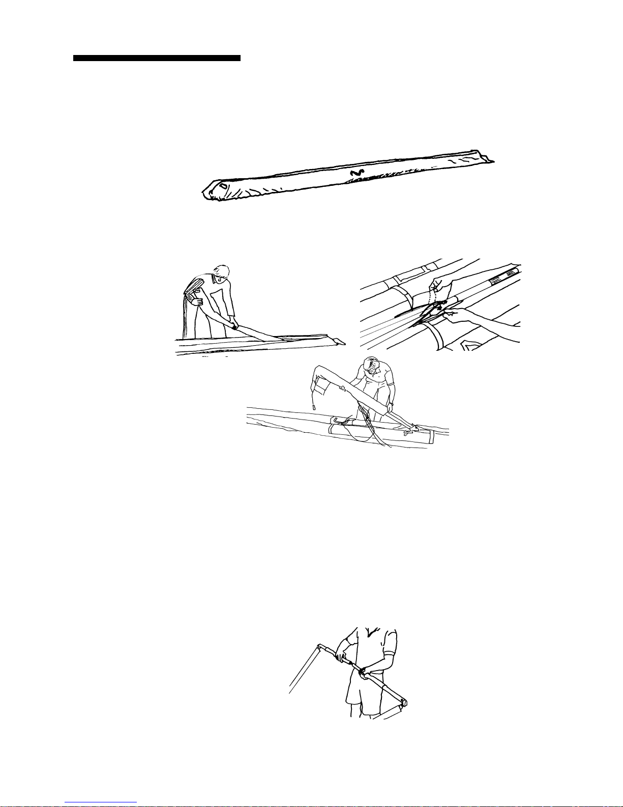
To break down the leading edges follow these steps
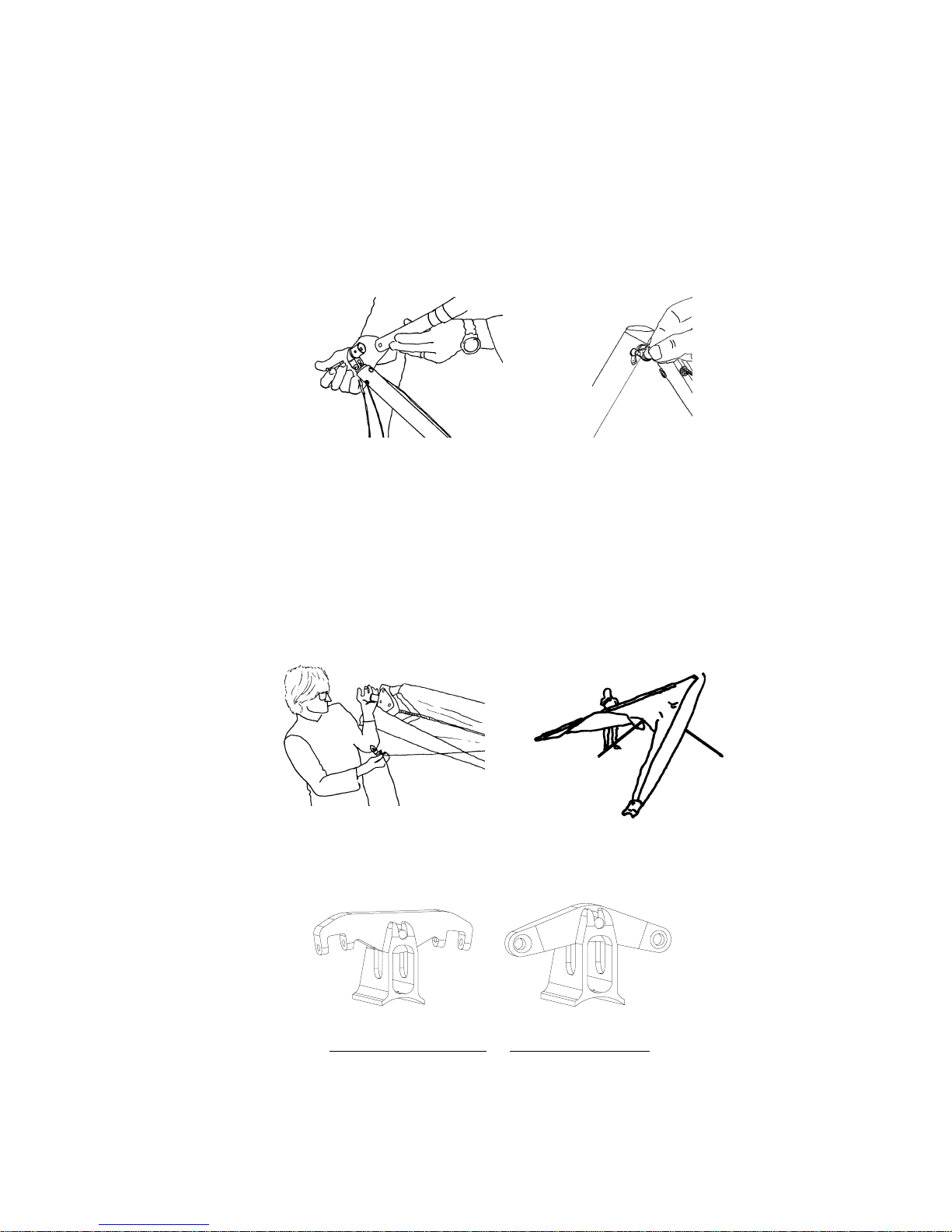
1. Lay the glider on the ground or floor, unzip and remove the bag and remove the velcro ties. Undo
the velcros which hold the sail around the sail mount plug. Pull the sail rearward at each tip to
dismount the sail from the rear leading edge.
2. Unzip the sprog access zipper in the bottom surface and disconnect the sprog bungee from the
sprog rear end paddle.
3. Obtain an indelible marker. Mark the rear leading edges left and right (remember that left and right
are reversed if the glider is lying on its back, upside down).
4. Pull the rear leading edge straight aft to disengage it from the front. Slide it forward inside the sail
until you can fold the sprog past the internal sail ribs, then remove the whole assembly from the
from the sail. Be very careful not to damage the sail with the hardware attached to the rear leading
edge. Tape or pad the edges of the front end of the rear leading edge tubes, and the rear of the front
leading edge tubes to prevent sail damage during transit.
5. Remove the carbon sandwich transverse batten from the sail by opening the velcro closure at the
#3 batten end of the transverse batten pocket and sliding the transverse batten out towards the wing
tip. Note that the orientation of the transverse batten is flat side closest to the bottom surface.
Be careful handling the transverse batten - carbon fiber splinters can be very dangerous.
Wrap and pad the transverse batten for shipment.
6. Carefully fold the rear of the sail over against the front, and replace the bag on the glider.
7

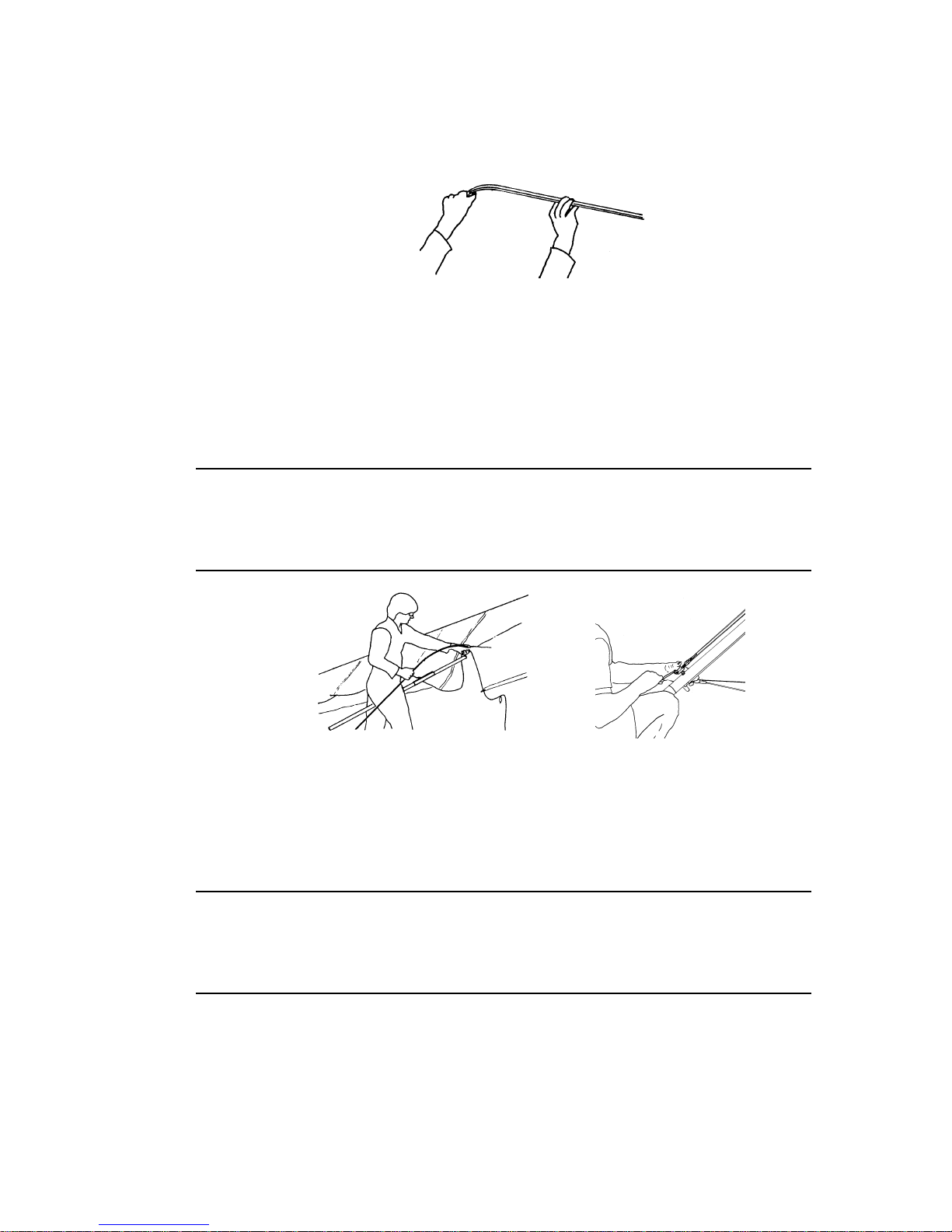
Remounting the rear leading edges
1. Install the transverse battens in the batten pockets. The proper orientation for the transverse
batten is with the flat carbon side (bottom side) of the batten facing the bottom surface of the
sail. The top side of the batten should lay flat in the pocket against the top surface of the sail.
Secure the velcro closure.
2. Make sure you are mounting the correct leading edge rear into the correct front (check the right /
left designation).
3. Slide the rear leading edge (through the sail past the edge of the front leading edge) far enough to
feed the sprog out through the curved bottom surface access zipper between the sail ribs on battens
no. 3 and no. 4. Engage the rear leading edge into the front. If the rear leading edge is properly
installed, the black plastic crescent adapter that is attached to the rear leading edge will be completely inside the front leading edge. (Note: On early serial production gliders the black crescent
may protrude 1/8" from the front leading edge when the rear leading edge is fully engaged.)
4. Remount the sail to the rear leading edge, making sure to align the sail mount webbing squarely in
the slot and attach the securing velcros.
The sail is mounted to the leading edge by the inner (forward) of the two loops of webbing. The outer loop is a pull handle only.
You may find it helpful to use a large, flat bladed screw driver to pry the sail mount webbing over
the end of the leading edge tube and into the slot. Take care not to damage the webbing.
5. Attach the sprog bungee to the sprog paddle. One end of the bungee is secured to a tab sew to the
sail body. Insert the free end of the bungee though the hole in the corresponding side of the paddle,
tie an overhand knot and push it back into the channel in the bottom of the paddle.
8
Fusion Set-Up Procedure
The Fusion has been specially designed to set up quickly and easily either on the control bar or flat on
the ground. We will first cover the steps for setting up on the control bar.
1. Lay the glider on the ground, with the bag zipper up, with the nose into the wind.
2. Undo the zipper, remove the battens, remove the protective pad at the rear wire station on the keel,
and remove the control bar bag. Newer gliders may have a pair of neoprene protective socks over
the rear wire junction and the end of the keel instead of a pad.
3. Unfold the control bar legs.
a. If the glider is equipped with a folding basetube:
i. Straighten the fold in the folding basetube.
ii. Preflight the folding basetube center hardware at this time, checking that the nuts
and coil spring pins are secure, and that the tangs are straight and in good condition.
iii. Slide the basetube center sleeve over the center joint until it is positioned between
the button spring pins. (Note: If you plan to clamp instruments to the basetube
center, position the center sleeve so that one button passes through the hole near
one end of the sleeve, which will secure the sleeve against rotation.)
9
b. If the glider is equipped with a non folding basetube:
i. Remove the safety ring, wing nut and bolt from the corner bracket.
ii. Insert the corner bracket all the way into the basetube.
iii. Install the bolt, wingnut and safety, securing the bracket to the basetube.
Make sure that the aluminum fitting is fully inserted into the basetube, and that the bolt is
through both the basetube and the fitting. If the hole in the fitting can be seen outside the end of
the basetube, the fitting is not fully installed, and will likely disengage in flight resulting in a
dangerous structural collapse and loss of control of the glider.
Do not insert the fitting at an angle, and do not force the fitting into the basetube if it does not slide
in freely. Check for dirt or damage to the fitting or the inside of the basetube. If the fitting is forced
into the basetube, it may be impossible to remove. See your dealer if the fitting becomes difficult to
install or remove.
4. Flip the glider upright on the control bar, and remove the bag and all the velcro ties. Do not remove
the leading edge tip protector bags at this time, but do loosen the velcros on the tip bags. If there is
more than eight m.p.h. of wind, or if the wind is gusty, turn the glider 90 degrees to the wind
direction. Spread the wings almost all the way.
5. Install the elevated hang system spreader bar onto the base pillar. Check for free pivoting movement of the spreader bar, and that the pivot pin is securely installed in the slot in the base pillar.
6. At this time, undo the velcro attachment of the two halves of the front keel pocket. This is to allow
the xbar center wedge and its rear webbing hold down strap to slide freely aft on the keel when you
tension the crossbar.
Webbing Hang System Perlon Hang System
10
7. Remove the battens from the batten bag, and check each batten for symmetry against the corre-
sponding batten from the other wing. Wills Wing convention is that black tipped battens go in the
right wing and white tipped battens in the left, except for the straight #1 plug on battens which all
have black tips.
8. Install the cambered top surface battens in the sail, leaving out the shortest two on each side (#2
and #3) for now. Each batten is secured by a double loop of the batten string. Order of insertion is
longest to shortest, from the root out. When inserting the inboard most battens, lift the keel to ease
the insertion. The longest battens may catch the edge of the mylar insert at the front of the sail. If
that happens, make sure that the mylar insert is not creased or folded in the pocket. When these
battens reach the back side of the leading edge tube, it may be necessary to lift the sail along the
batten pocket to facilitate insertion of the batten all the way.
Insert the battens carefully, so as to minimize stress and wear on the sail. Never insert or
remove top surface battens with the crossbar tensioned (except for up to the last four on
each side) and never insert or remove battens with heavy wind pressure on the top of the
sail or in any condition which causes the battens to slide with great resistance in the pockets.
9. Spread the wings all the way and check all cables for any twisted thimbles or tangled cables.
10. At the rear of the keel, tension the crossbar and secure the crossbar sweep wire by pulling the
keyhole channel aft along the keel until the large hole lines up with the keyhole bolt. Lower the
keyhole bracket over the bolt until the channel can slide forward so that the narrow part of the
keyhole slot is fully captive in the narrow part of the bolt collar.
Never install the keyhole channel onto the keyhole bolt without making absolutely sure
that the channel is fully engaged on the narrow neck of the bolt, and tensioned forward
into the fully locked position. An in-flight disengagement of this attachment will cause a
complete loss of structural support of the glider and a total loss of control.
11. Overlap the mating velcro surfaces of the front keel pocket around the bottom of the keel tube and
secure them together. The VG activation rope should be inside the keel pocket.
11
12. Remove the wingtip protector bags. Install the last two curved battens on each side.
13. Reach in through the end of the sail at the tip, grasp the floating washout tube and align it for
insertion into the washout tube sleeve. Make sure when inserting it that the washout tube slides all
the way home into the sleeve. It helps to lift the end of the #2 batten. Check the washout tube to
make sure it is secure and free to float up and down.
14. Install the plug-on #1 battens by inserting one end through the hole in the bottom surface at the tip
and engaging the forked batten tip on the clevis pin standoff on the top of the leading edge tube.
The #1 batten should bear on the top side of the washout tube. Secure with a double loop of the
505 batten string. The proper #1 tension for the Fusion is very tight and it is easiest to install the
batten string if you first set the VG to the full tight position.
Be sure to re-set the VG to the desired setting prior to launch.
15. At this time preflight the following from the open end of the wingtip:
a. The sail mount webbing - make sure that the sail is mounted by the inner loop of webbing,
and that the webbing is laying flat in the bottom of the slot in the sail mount endcap.
b. The number one batten clevis pin and safety.
c. The washout tube installation.
d. That the internal rib in the #2 batten is zipped.
16. Install the plastic wing tip fairing, or the optional winglet. Make sure that the fairing or winglet is
fully inserted into the leading edge such that the velcro mates securely around the entire perimeter.
While installing the tip fairing or winglet, support the aft tip of the number one batten as necessary
12
so as to equalize the tension around the perimeter of the open end of the sail at the wing tip to
insure that the sail mates properly to the tip fairing or winglet.
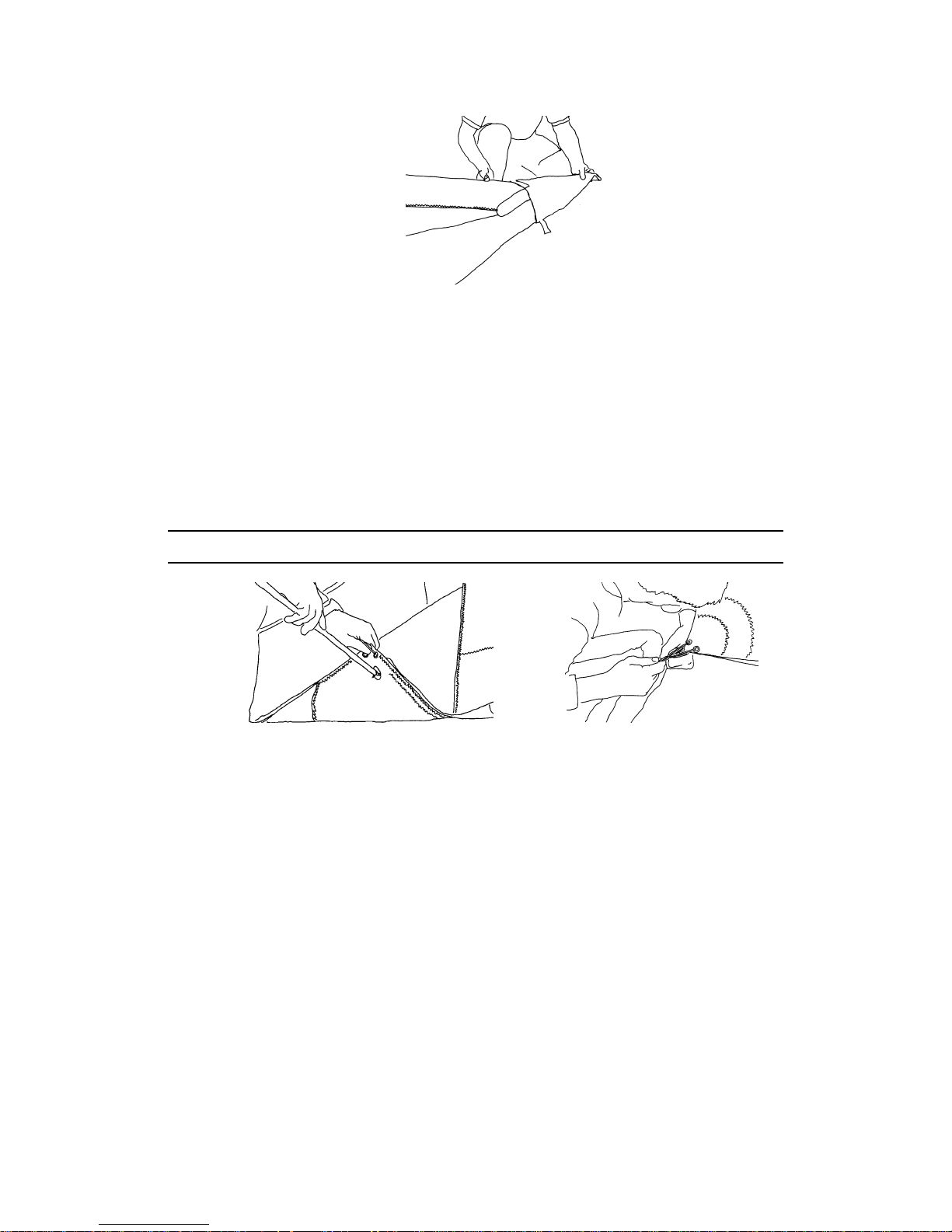
17. Open the V shaped access zipper in the outboard section of the bottom surface. Swing the sprog
back and outwards, until the rear sprog paddle is aligned underneath the transverse batten in the
top surface sail pocket just forward of the rear of the bottom surface. Attach the clip in the sail to
the ring or loop on the sprog paddle to secure the sprog in position. Check the sprog for freedom of
upward motion and that it is securely restrained at the downward limit by the sprog cable. Check
the cable and the associated attachment fittings. The neoprene cover at the center of the sprog can
be slid aft to inspect the cable attachment at this point. Early model Fusions have an opposing
bungee to lightly tension the sprog retaining clip. The bungee is unnecessary because the sail rib
effectively prevents the sprog from rotating inboard.
18. While in this area, check the internal rib zipper for the rib adjacent to the sprog. Also, from this
point you can visually inspect the cam lever plate, support strap, cable attachment and bolts, nuts
and safeties at the crossbar / leading edge junction. When finished, zip up the sprog access zipper.
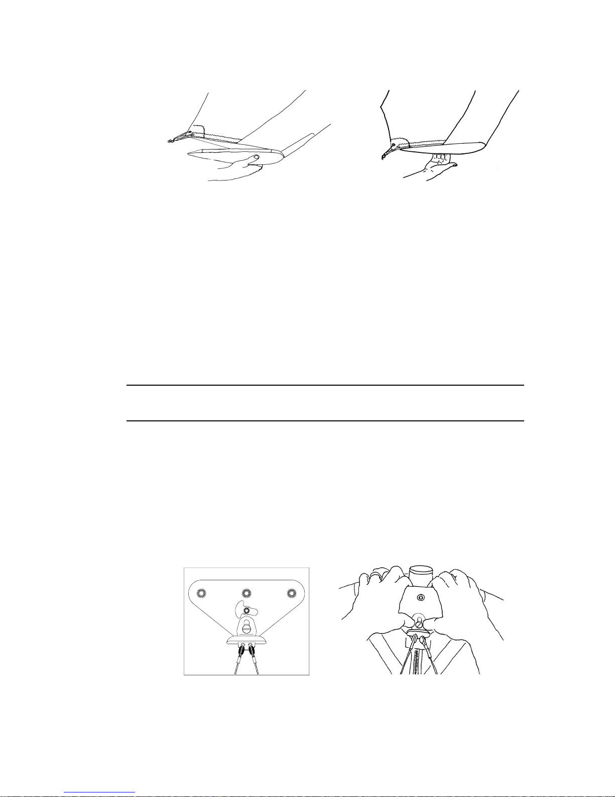
Before attempting to install the bottom nose wires be sure that the control bar apex is
pushed into place fully aft on the slider track.
19. Attach the bottom front wires to the bottom of the nose. In order to attach or remove the keyhole
tang from the collared bolt, the aluminum anchor lock must be rotated into the position shown
below, left. Once this is done, install the keyhole tang over the collared bolt by pulling down on the
nose of the glider while pressing the tang upwards over the collared bolt. Remember, it is the
pulling down of the glider's nose rather than the upward pressure on the tang that allows you to
install the tang over the bolt.
If you have difficulty installing the tang, the apex is fully aft, and no wires are twisted or thimbles
cocked, it is probably because the glider is not sitting on level ground.
After installing the keyhole tang, rotate the aluminum anchor lock as shown to secure the tang on
the bolt.
13
 Loading...