

Wills Wing Alpha 180, Alpha 210 Owner's Service Manual
Alpha 180 and 210
Owner / Service Manual
June 2015


Alpha 180 and 210
Copyright © 2015 by Sport Kites, Inc. dba Wills Wing, Inc. All rights reserved.
No part of this manual may be reproduced in any form without the express written permission of
Sport Kites, Inc., dba Wills Wing, Inc.
June 2015 - First Edition
500 West Blueridge Ave • Orange, CA • 92865 • Phone (714) 998-6359 • FAX (714) 998-0647
http://www.willswing.com • E-mail: comments@willswing.com


Contents
Introduction ...................................................................................................... 1
Disclaimer And Warning ................................................................................... 2
Technical Information And Placarded Operating Limitations .................................3
A Note About Platform Towing .........................................................................5
A Note About High Duty Cycle Operations ......................................................... 6
A Note About Parts Replacement ......................................................................6
Alpha Breakdown Procedure For Shipping And Reassembly Procedure ................. 6
Launching And Flying The Alpha ......................................................................15
Using Wing Tufts ............................................................................................ 15
Trimming Your Glider In Pitch ..........................................................................18
Speeds To Fly And Using Your Airspeed Indicator .............................................19
Landing The Alpha .......................................................................................... 20
Alpha Breakdown ...........................................................................................24
Alpha Stability Systems ..................................................................................25
Maintenance Schedule ....................................................................................27
Removing The Sail From The Airframe And Re-installing ...................................28
Tuning ...........................................................................................................30
Car Top Mounting And Transport ....................................................................32
In Closing .......................................................................................................33
HGMA Compliance Verification .......................................................................34
Frame Plans ....................................................................................................36
Assembly Diagrams ........................................................................................39


Introduction
Thank you for purchasing a Wills Wing glider, and welcome to the world wide family of Wills Wing
pilots. We are a company of pilots and aviation enthusiasts, and our goal is to serve your ying needs
now and in the future, as we have done for pilots throughout the world since 1973.
We encourage you to read this manual thoroughly for information on the proper use and maintenance
of your Wills Wing glider. If at any time you have questions about your glider, or about any aspect of
hang gliding that your Wills Wing dealer cannot answer, please feel free to give us a call.
Please visit our web site at http://www.willswing.com on a regular basis. The site features extensive
information about Wills Wing gliders and products, a Wills Wing Dealer directory, a comprehensive
list of service and technical bulletins, current editions of owners manuals, our complete retail price
list, a search engine, and more. Our web site is the means by which we will communicate with you
when we have service advisories or other information related to your safety that we need to make you
aware of.
We wish you a safe and enjoyable ying career, and, once again, welcome aboard!
Mike Meier, Linda Meier, and Steve Pearson
Wills Wing, Inc.
— 1 —

Disclaimer And Warning
Hang gliding is a form of aviation. Like any form of aviation, its safe practice demands the consistent
exercise of pilot skill, knowledge of airmanship and weather, judgment and attention at a level which
is appropriate to the demands of each individual situation. Pilots who do not possess or exercise the
required knowledge, skills and judgment are frequently injured and killed. The statistical rate at which
fatalities occur in hang gliding is approximately one per thousand participants per year.
The Federal Aviation Administration does not require a pilot’s license to operate a hang glider. Hang
gliders and hang gliding equipment are not designed, manufactured, tested or certied to any state
or federal government airworthiness standards or requirements. Hang Gliders are not required to be
registered with the Federal government. As a result, we do not have a reliable way to keep track of
contact information for the owners of Wills Wing hang gliders. It is your responsibility to check with
us periodically for safety and airworthiness advisories and information related to your glider. The
easiest way to do this is to check our web site at http://www.willswing.com Wills Wing hang gliding
products are not covered by product liability insurance. You should never attempt to y a hang glider
without having received competent instruction. We recommend that you not participate in hang gliding unless you recognize and wish to personally assume the associated risks.
Please y safely.
Wills Wing, Inc.
— 2 —

Technical Information And Placarded Operating Limitations
The Alpha 180 and 210 have been tested and found to comply with the 2014 HGMA Airworthiness
Standards. At the time of this writing – June 1st, 2015, no certicates of compliance have been issued
for these models. Please see www.HGMA.net for updated information on the HGMA certication
status of any hang glider
The HGMA Certication standards require:
1. A positive load test at root stall angle of attack at a speed equal to at least the greatest of:
a. 141% of the placarded maximum maneuvering speed
b. 141% of the placarded maximum rough air speed
c. 123% of the placarded speed never to exceed
for at least three seconds without failure.
The required test speed for the Alpha was 54 m.p.h..
2. A negative 30 degree angle of attack load test at a speed equal to at least the greatest of:
a. 100% of the placarded maximum maneuvering speed
b. 100% of the placarded maximum rough air speed
c. 87% of the placarded speed never to exceed
for at least 3 seconds without failure.
The required test speed for the Alpha was 38 m.p.h..
3. A negative 150 degree angle of attack load test at a speed equal to at least the greater of 26 mph
or 50% of the required positive load test speed for at least 3 seconds without failure.
The required test speed for the Alpha was 27 m.p.h..
4. For the Alpha 180 and 210, pitch tests at speeds of 20 m.p.h., 32 m.p.h. and 44 m.p.h. which show
the glider to have a positive pitching moment coefcient over a range of angles of attack from
trim angle to 20 degrees below zero lift angle at 20 m.p.h., and from trim angle to 10 degrees
below zero lift angle at 32 m.p.h., and from 10 degrees above zero lift angle to zero lift angle at
44 m.p.h.
5. Flight maneuvers which show the glider to be adequately stable and controllable throughout the
normal range of operation.
The Alpha 180 and 210 have been designed for foot launched soaring ight. They have not been designed to be motorized, tethered, or towed. They can be towed successfully using proper towing procedures. Pilots wishing to tow should be USHGA skill rated for towing, and should avail themselves
of all available information on the most current proper and safe towing procedures. Suggested sources
for towing information include the United States Hang Gliding Association and the manufacturer of
the towing winch / or equipment being used. Wills Wing makes no warranty of the suitability of the glider
for towing.
Flight operation of the Alpha should be limited to non aerobatic maneuvers; those in which the pitch
angle will not exceed 30 degrees nose up or nose down from the horizon, and the bank angle will not
exceed 60 degrees. The Alpha is generally resistant to spinning, but will spin from a stalled turn if the
— 3 —

pilot applies positive pitch control in a moderate to steep bank at a high rate or in combination with
roll control input so as to roll towards the high wing. Recovery from a spin requires unstalling of the
wing, and it is therefore important that in the event of a spin, no application of nose up pitch control
be held. The Alpha will recover from a spin once control pressures are relaxed. As the nose lowers and the angle of attack is reduced, the stall will be broken and the spin will stop. However, such
recovery will consume signicant altitude, and will result in the glider assuming an unpredictable
heading. Recovery from a spin may therefore involve a ight trajectory which intersects the terrain at
a high rate of speed. An aggravated spin could result in loss of control, in ight inversion, and structural failure. Therefore no attempt should ever be made to deliberately spin the glider. Care should be
taken not to set the hang point too far aft in a manner that causes the trim speed to be too close to the
stall speed, as this will increase the chance of entering a spin inadvertently. (See the sections in this
manual on “Using Wing Tufts” and “Trimming The Glider In Pitch” for more information.
The maximum steady state speed for a prone pilot in the middle of the recommended weight range
full forward on the control bar is approximately 34 mph for the Alpha 210 and approximately 37 mph
for the Alpha 180. The placarded speed never to exceed for the Alpha is 44 mph, and the maneuvering / rough air speed is 38 mph. The Alpha can be own in steady state high speed ight with the
pilot full forward over the bar in a normal prone position without exceeding the VNE speed, however
maneuvering ight may result in speeds in excess of Vne. Abrupt maneuvers should not be made at
speeds above 38 mph.
The stability, controllability, and structural strength of a properly maintained Alpha have been determined to be adequate for safe operation when the glider is operated within all of the manufacturer
specied limitations. No warranty of adequate stability, controllability, or structural strength is made
or implied for operation outside of these limitations.
The stall speed of the Alpha at maximum recommended wing loading is 25 mph or less. The top
(steady state) speed at minimum recommended wing loading for a prone pilot with a properly designed and adjusted harness is at least 32 mph.
All speeds given above are indicated airspeeds, for a properly calibrated airspeed indicator mounted
in the vicinity of the pilot. Such an airspeed indicator is available through your Wills Wing dealer.
The recommended hook in pilot weight range for the Alpha is:
Apha 180: 125 – 200 lbs
Alpha 210: 150 - 280 lbs.
Be advised that pilots with hook in weights of less than 120% of the minimum hook in weight will
nd the Alpha somewhat more demanding of pilot skill to y, and that pilots hooking in at more than
85% of the maximum hook in weight some relative degradation of optimum sink rate performance
due to their higher wing loading. Please note that the term “recommended pilot hook in weight” refers to the weight range within which the glider meets the basic minimum performance and handling
standards for which the glider was designed. When choosing among two sizes, the more appropriate
information to use would be the optimum pilot hook in weight range which is 144 lbs to 175 lbs for
the Alpha 180, and 176 lbs to 240 lbs for the Alpha 210.
A minimum USHGA Novice (II) level of pilot prociency is required to y the Alpha safely, unless
under the direct supervision of a qualied instructor.
Operation of the glider by unqualied or under qualied pilots may be dangerous.
— 4 —
Due to the limited speed range of the Alpha and the relatively low glide ratio when own at its maximum speed, particular care should be exercised when ying in winds of more than 10 mph.
Operating the Alpha outside of the above limitations may result in injury and death. Flying the Alpha
in the presence of strong or gusty winds, or turbulence may result in loss of control of the glider
which may lead to injury and death. Do not y in such conditions unless you realize and wish to personally assume the associated risks. Wills Wing is well aware that pilots have, and continue to perform maneuvers and y in conditions which are outside the recommended operating limitations stated
herein. Please be aware that the fact that some pilots have exceeded these limitations in the past without dangerous incident does not imply or insure that the limitations may be exceeded without risk. We
know for a fact gliders which meet all current industry standards for airworthiness can and do suffer
in ight structural failures, both as a result of turbulence, and as a result of various maneuvers outside
the placarded operating limitations, including, but not necessarily limited to aerobatics. We do not
know, and cannot know, the full range of maneuvers or conditions which may cause the pilot's safety
to be compromised, nor can we test the glider in all possible circumstances.
A Note About Platform Towing
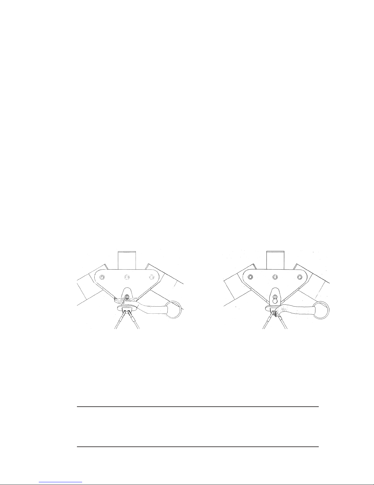
When platform towing, it is necessary to attach a nose line to the front of the glider, to restrain the
glider at the proper pitch attitude while on the tow platform. If the noseline is installed improperly, it
is possible for it to cause the bottom front wires to become detached from the nose of the glider as the
glider departs the platform during launch, which will result in a complete loss of control of the glider
and a very dangerous crash. Please see the diagrams below for the correct way and one incorrect way
to install the nose line.
Correct Attachment Incorrect Attachment - Unsafe!
When routed incorrectly, the nose line is simultaneously pulling down on the keel, and forward on
the front wires and/or tang - which is exactly what is required to disengage the tang from the keyhole
collar. In addition, because the nose line also normally pulls forward from the nose of the glider, it
will normally restrain the front wires in approximately the normal position, until tension on the nose
line is released upon launch from the platform. As a result, it may not be apparent that the front wires
have become disconnected, or are in danger of being disconnected from the nose.
Please note that the nose line must not be routed in any way such that it can pull forward
on the nose wires or the nose tang. The incorrect routing shown is one example of a way
in which this could happen. It could also happen, however, if the nose line is routed outside the V of the wires, but behind the tang handle.
— 5 —

Please note that the button safety lock may not be effective in preventing the nose wires
from being disconnected by an improperly routed nose line. Make sure that the nose cone
is not installed in such a way as to depress the button lock.
All pilots planning to platform tow using a Wills Wing glider tted with the keyhole tang
nose catch must, as their last checklist item prior to "going to cruise," positively verify
that the nose line is not routed in such a way that there is any possibility that it can cause
the nose wires to disconnect.
A Note About High Duty Cycle Operations
Gliders which are used in a training environment, or in any situation which involves a high number of
ight operations over short period of time, will require an accelerated maintenance program in order
to maintain adequate airworthiness. The design and testing of these gliders does not necessarily take
into account the types of wear which may result from high duty cycle operations. The operator must
take responsibility to thoroughly and adequately inspect the glider to determine whether maintenance
is being conducted on a schedule appropriate to maintain the airworthiness of the glider.
A Note About Parts Replacement
When ordering replacement parts, it is very important to provide the glider serial number to insure
that the correct replacement parts are provided. The serial number is a ve digit number, and can normally be found in three places on the glider - written inside the nose of the sail (most reliable), on an
adhesive label on the bottom of the keel at the nose, and written on the operating limitations placard
on the bottom of the rear of the keel.
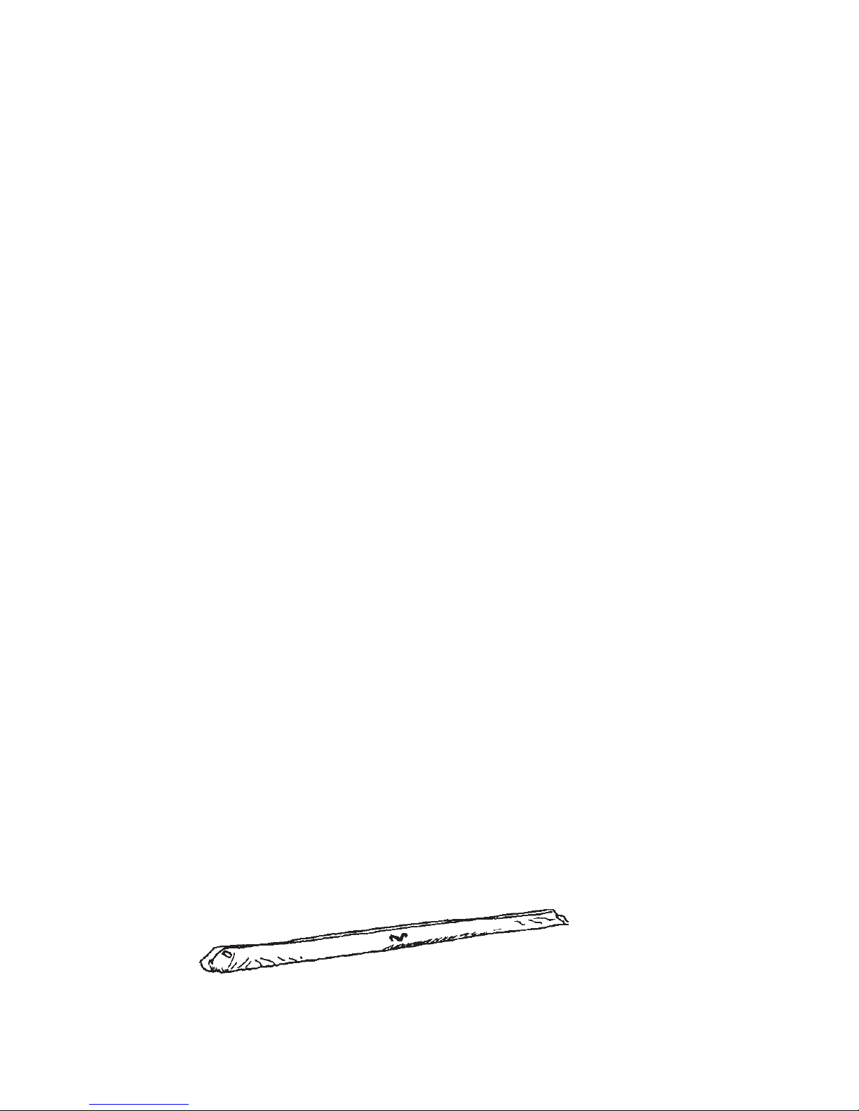
Alpha Breakdown Procedure For Shipping And Reassembly Procedure
The Alpha 180 and 210 can be broken down to approximately 12.5 feet and 13.5 feet respectively by
removal of the rear leading edges. The rear leading edge is pinned at its forward end with a clevis pin
which secures it to the front leading edge spar.
To break down the leading edges follow these steps
1. Lay the glider on the ground or oor, unzip and remove the bag and remove the Velcro ties. Undo
the velcros which hold the sail around the sail mount plug and pull the sail rearward at each tip to
dismount the sail from the rear leading edge. You may use a large, at bladed screw driver to pry
to sail mount webbing away from the slotted endcap. Take care that the screwdriver does not have
any sharp edge with might cut or damage the webbing.
2. Obtain an indelible marker. Mark the rear leading edges left and right (remember that left and
right are reversed if the glider is lying "on it's back", upside down.
3. Remove the clevis pin that secures the rear leading edge and pull it straight aft to disengage it
from the front. Put tape on the sharp edges of the front end of the rear leading edge tubes.
— 6 —
4. Lay the mylar pockets at so as to avoid creasing the mylar when you fold over the rear portio
of the sail. Replace the sail ties loosely, zip up the bag, and carefully fold the rear of the sail over
against the front.
Remounting the rear leading edges
1. Set the glider on its back (upside down). Unfold the glider, open the bag and lay the sail out full
length. Make sure you are mounting the correct leading edge rear into the correct front (check the
"right" / "left" designation) and remember that left and right are reversed when the glider is lying
upside down, on its back.
2. Wipe the forward six inches of the rear leading edge with a clean cloth to remove any dirt or grit.
3. Slide the rear leading edge tube into the sail and then into the front leading edge, as far as it will
go until you encounter a hard stop. This will be the forward edge of the rear leading edge contacting the the front leading edge.
4. Rotate the rear leading edge so that the washout tube receptacle faces inwards, towards the oppo-
site leading edge and “down” towards the ground (upwards relative to the glider) while maintaining forward pressure on the rear leading edge. Somewhere in this range of orientation, the hole
through the front leading edge sleeve will line up with the corresponding hole in the rear leading
edge. Install the clevis pin with the head in the forward and the safety on the back of the leading
edge. Pull the sail down the leading edge.
5. Remount the sail to the rear leading edge, making sure to align the inner sail mount webbing
(NOT the outer handle webbing) squarely in the slot and attach the securing velcros. Verify that
the sail is oriented properly – the hole in the bottom surface for the washout tube should align
with the washout receptacle.
You may nd it helpful to use a large, at bladed screw driver to pry the sail mount webbing over
the end of the leading edge tube and into the slot. Take care not to damage the webbing. Alternately,
rst remove the sail mount screws located at the front of each leading edge to release the tension. The
sail mount screws may be difcult to replace until after the glider is completely assembled. Spread
the wings carefully and incrementally while pulling the sail forward at the nose during assembly to
prevent damage to the sail.
Alpha Set-Up Procedure
The Alpha has not been designed to be set up while at on the ground, or to be laid at on the ground
after set-up – the geometry of the airframe, particularly on the 210, does not allow this. Use the following procedure to set up the Alpha.
1. With the glider in the bag, lay the glider on the ground, zipper up, with the nose into the wind. If
there is more than ve mph of wind, or if the wind is gusty, turn the glider slightly more than 90
degrees to the wind direction.
2. Undo the zipper, remove the battens, and remove the control bar bag.
— 7 —
3. Separate the control bar legs.
a. Remove the safety ring, speed nut and bolt from the corner bracket.
b. Insert the basetube into the corner bracket so that the holes line up.
c. Install the bolt, nut and safety, securing the bracket to the basetube.
Make sure that the bolt passes through both the bracket and the basetube, thus securing
the basetube to the bracket.
Proper orientation of the basetube during installation will result in the "Wills Wing" sticker being
on top of the basetube and right side up when viewed while hooked into the glider in the normal
ying position.
Do not insert the basetube into the tting at an angle, and do not force the tting onto the
basetube if it does not slide on freely. Check for dirt or damage to the inside of the tting or the outside of the basetube. If the tting is forced onto the basetube, it may be impossible to remove. See your dealer if the tting becomes difcult to install or remove.
4. Flip the glider upright and set it on the control bar, and remove the glider bag and all Velcro sail
ties.
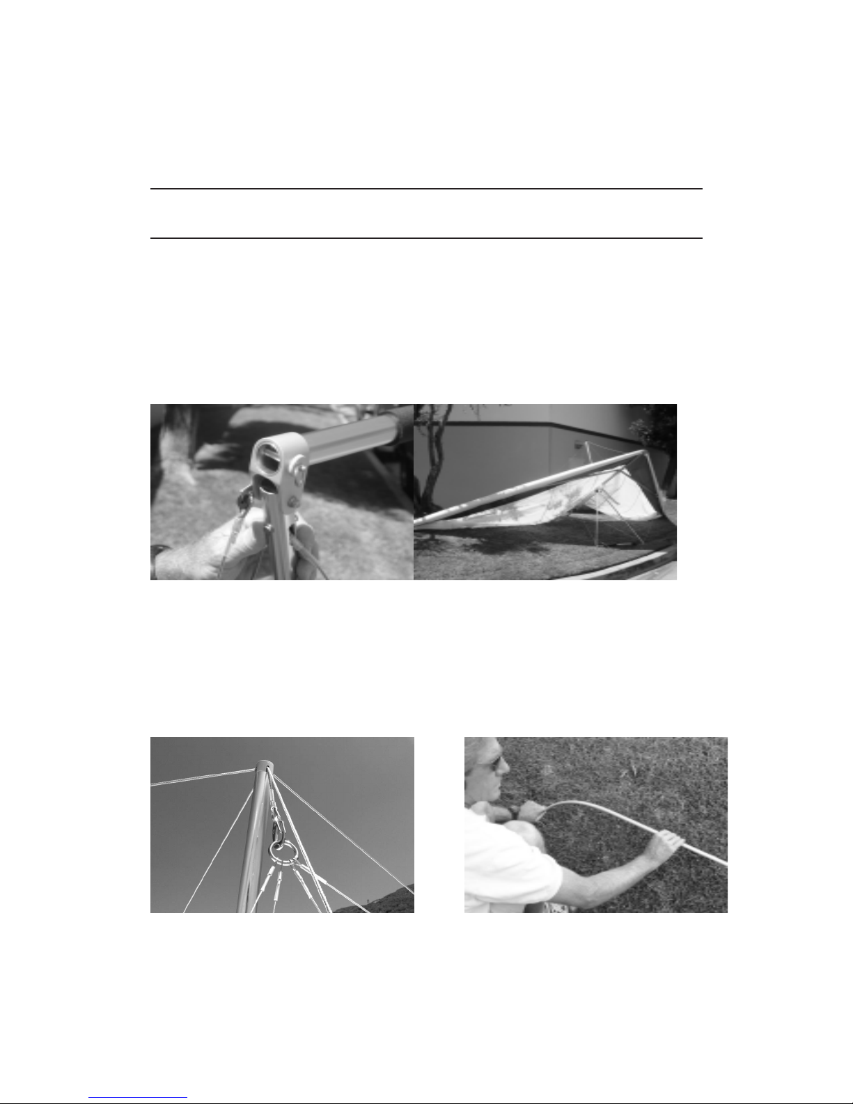
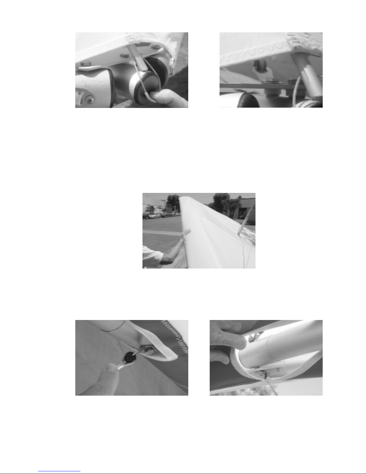
5. Spread the wings almost all the way. Raise the kingpost to a vertical position, checking to make
sure that the top front and top side wires are not wrapped around the kingpost.
6. Attach the bridle ring to the snap hook at this time, taking care that there is not a twist or rotation
in the bridle ring which causes the bridle lines to cross over one another.
7. Lay out the battens and check each batten for symmetry against the corresponding batten from
the other wing. Wills Wing convention is that black tipped battens go in the right wing and white
tipped battens in the left, except for the straight #1 plug-on battens which may both have the same
color tips.
— 8 —
8. Install the three longest cambered top surface battens on each side in the sail. Order of insertion is
longest to shortest, from the root out. Do not install the securing strings on the rear at this time.
9. Spread the wings all the way and check all cables for any twisted thimbles or tangled cables.
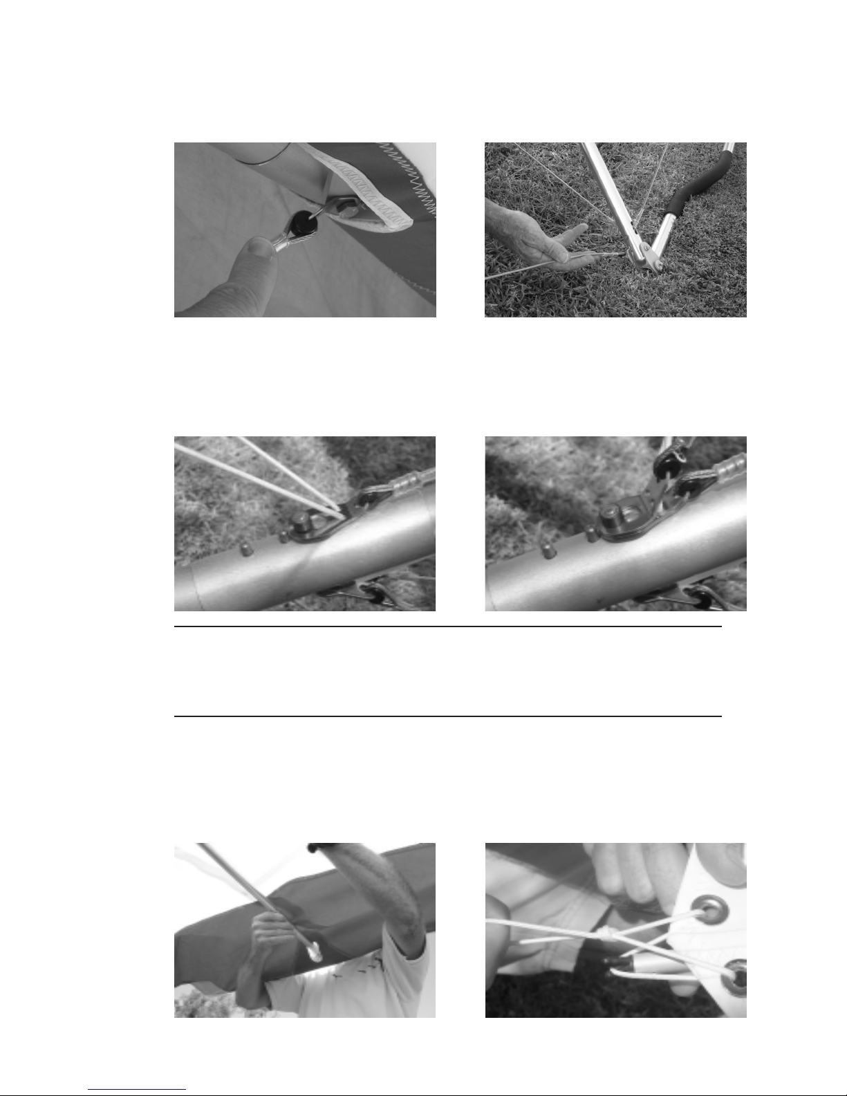
10. At the rear of the keel, tension the crossbar by pulling on the rope loop which is attached to the
sweep wire keyhole tang. Drop the keyhole tang all the way down over the top portion of the keyhole collar, and let it slide forward into the locked position. The button lock should snap up into
place behind the rear end of the tang. Next attach the keyhole tang for the top rear wire, and again
verify that the button lock snaps into place behind it.
Never install the keyhole tangs onto the keyhole collar without making absolutely sure
that they are fully engaged on the narrow neck of the collar and slid forward into the fully
locked position. An in-ight disengagement of this attachment will cause a complete loss
of structural support of the glider and a total loss of control.
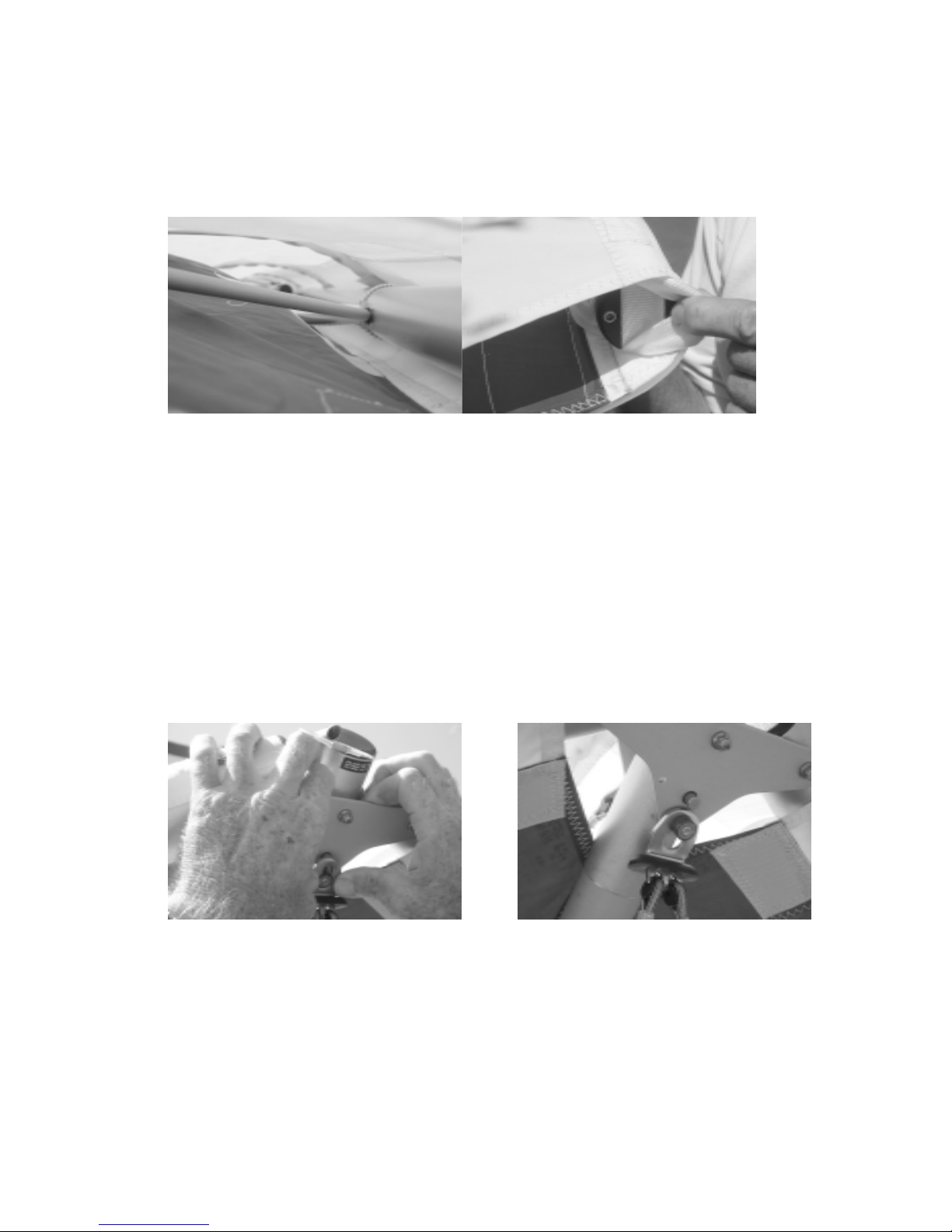
11. Remove the tip cover bags. Install the washout tips by plugging them straight into the receptacles
in the back side of the leading edge tube near the tip. Make sure that they are inserted as far as
they will go and that there is tension on the bungee holding them in place.
12. Install the remaining cambered battens, and secure all of the cambered battens with a double loop
of battens string.
— 9 —
13. Insert the straight #1 battens through the loop of 505 cord and between the top and bottom
sail surface at the tip, and plug the forked batten tip onto the stud on the back side of the leading edge tube. Secure the batten with a double loop of the 505 cord. The tension on the #1
batten cord should be rm, but not so tight that is slackens the sail mount webbing at the
leading edge sail mount endcap. If the #1 batten cord is too tight it will make the glider less
responsive to turn input at slow speeds, and more likely to enter a spin from a stalled turn.
14. At this time preight the following from the open end of the wingtip:
a. The sail mount webbing - make sure that the inner loop of webbing is laying at in the
bottom of the slot in the sail mount endcap.
b. The number one batten engagement on the clevis pin.
c. The safety ring on the clevis pin that secures the front end of the rear leading edge tube
15. Go to the nose and attach the keyhole tang securing the bottom front wires, by pulling down on
the nose of the glider while pressing the tang upwards over the shouldered bolt. (Remember it is
the pulling down of the glider’s nose rather than the upward pressure on the tang that allows you
to install the tang over the bolt. If you have difculty installing the tang, and no wires are twisted
or thimbles cocked, it is probably because the glider is not sitting on level ground.) Make sure
that the spring loaded button lock pops up behind the tang, securing it in place.
16. Push the nose batten fully back into the sail and lift the open end of the batten onto the stud on
the top of the keel. Look into the noseplate and preight the top front wire. Preight each of the
lockuts on the bottom of the noseplate - make sure they are tight, and that the bolt extends at least
one full thread beyond the nut.
— 10 —
16. Conduct a complete preight of the glider, according to the following procedure, checking all
assemblies which have not already been checked. Every bolt, nut, pin, safety ring, and fastener
of any kind should be checked during every pre-ight. A full pre-ight inspection should precede
every ight you make, not just the rst ight of the day.
Along the left leading edge
Check that the mylar insert is lying at in the mylar pocket, and that it is not severely creased
or buckled. A sharp crease in the mylar insert could cause a premature stall, or stall hysteresis
(delayed stall recovery) that can adversely affect both handling and performance.
Check the nut which secures the leading edge crossbar bracket to the leading edge, and check
the nut and the white nylon threaded nut cap which secure the crossbar to the bracket. On
the Alpha 210, the top side wires are secured to the crossbar by a separate bolt, inboard of
the crossbar / leading edge junction – check this assembly as well. Check that the sail is not
caught on the crossbar end, nor on any of the hardware.
Check that there are no cocked thimbles on either end of either bottom side wire, or on the
crossbar end of the top side wire.
— 11 —
 Loading...