

WillowWood LimbLogic Pump Instructions Manual

LimbLogic®
Prosthetist
Instructions
WHAT'S IN THE BOX
LimbLogic Pump*
Battery Charger*
Fob
Fob Battery (quantity=2)
Fob Key Ring
Diagnostic Disc or Sheet and Sealing Gasket (packaged together)
Exhaust Port Drain Tube
Replacement Exhaust Hose and Muffler*
Patient Instructions
Prosthetist Instructions
Quick-Start Guide
*Quantity = 2 for bilateral kit
This document provides instruction for the prosthetist in the
installation and use of the system. A separate document,
LimbLogic Patient Instructions, is included with each system
and should be provided to the patient upon delivery of a
prosthesis containing the LimbLogic.
The Vacuum Pump and fob included in this package are
electronically keyed together. They can be used only with
each other unless they are re-keyed with a LImbLogic
Communicator.
1

There are no field-serviceable parts inside the
Vacuum Pump. Opening the Vacuum Pump or
charger may result in injury or death and will
void the warranty.
Unauthorized changes or modifications to the
LimbLogic pump or accessories may; impair their
function resulting in injury or death, will void the
warranty, and may prevent their compliance with
relevant standards.
This pump is only designed to move air; use of
Vaseline® or similar lubricating creams inside the
socket will clog the pump. Do not allow foreign
substances to be pulled through the Vacuum Pump.
This may impair function of your vacuum system.
Do not allow acetone to contact the Vacuum Pump or fob.
All LimbLogic components have passed safety
testing for use as medical devices. Radio enabled
devices comply with United States and international
guidelines for low power transceivers. If LimbLogic
components will be used around safety critical
devices such as pacemakers or defibrillators, consult
the manufacturer for appropriate usage instructions.
Failure to do so may result in injury or death. Consult
the section on Regulatory Information for more
information on safety and compliance.
LimbLogic is designed for use by a single patient only.
Use on more than one patient may result in crosscontamination potentially causing a serious infection.
Charge the Vacuum Pump in a well-ventilated area
at a temperature between 5 °C (41 °F) and 33 °C
(90 °F). Failure to do so may result in prolonged or
incomplete charging of the Vacuum Pump and
may damage the Vacuum Pump.
A Vacuum Pump enclosed by a cosmetic cover will
retain heat, but in most cases should charge
normally at temperatures below 27 °C (80 °F). The
battery may not fully charge at higher temperatures.
Use of the LimbLogic at temperatures above 41 °C
(106 °F) may heat the surface of the product to
unsafe temperatures which could cause burns with
extended contact. Use care when operating the
LimbLogic at high temperatures.
LimbLogic has been constructed using polymer
materials to create a durable, lightweight, watertight, and radio-transparent design. These materials
have all been certified to an inflammability rating of
at least HB per UL 94. However, polymers can melt
or burn if exposed to high temperatures or flame.
Do not expose your LimbLogic product to these
conditions. Doing so may result in ignition resulting
in injury or death.
LimbLogic pumps cannot compensate for failures in
the associated prosthetic socket or sealing system.
Only use LimbLogic pumps with commercially proven
socket and sealing systems. Use with other sealing
systems may result in loss of suspension resulting in
injury or death.
Electrical equipment can interact. Do not operate
the fob, charger, or either LimbLogic pump design
while they are stacked upon, or in close proximity
to, other electrical equipment without monitoring
performance. Doing so may result in equipment
malfunction or failure.
2

The Side Mount LimbLogic Vacuum Pump has been
designed and tested for mounting on transfemoral
sockets. Use in other configurations may result in
tripping or other hazards.
FCC NOTICE
Note:
This device complies with part 15 of the FCC Rules. Operation
is subject to the following two conditions: (1) This device may
not cause harmful interference, and (2) this device must accept
any interference received, including interference that may cause
undesired operation.
Changes or modifications not approved by The Ohio Willow Wood
Company may degrade performance, possibly leading to injury or
death and will void the user’s authority to operate this equipment.
IC Notice
Note:
This device complies with Industry Canada RSS standards
applicable to radio devices. Operation is subject to the following
two conditions: (1) this device may not cause interference, and (2)
the user of the device must accept any interference, including
interference that may cause undesired operation.
Remarque:
Le présent appareil est conforme aux CNR d‘Industrie Canada
applicables aux appareils radio . L‘exploitation est autorisée aux
deux conditions suivantes: (1) l‘appareil ne doit pas produire
de brouillage, et (2) l‘utilisateur de l‘appareil doit accepter tout
brouillage radioélectrique subi, même si le brouillage est
susceptible d‘en compromettre le fonctionnement.Cuppl. Edius
maxim in sultilin hendio hoc revid dii tem anterfectam ur atiam
3

TABLE OF CONTENTS
Page
Installing the Fob Battery ...............................................................................5
Quick-Start Guide ...............................................................................................6
Fob Guide ...............................................................................................................6
Keys to Successful Use .....................................................................................7
Introduction ...........................................................................................................8
Vacuum System Function ...............................................................................8
Charging the Vacuum Pump Battery ........................................................9
Charging the Vacuum Pump Battery Outside the U.S. ..................10
Charging the Vacuum Pump Battery in a Vehicle .............................10
Turning On the Vacuum Pump ...................................................................10
Turning O the Vacuum Pump.....................................................................11
Resetting the Vacuum Pump ........................................................................11
Turning On the Fob ............................................................................................11
Changing Vacuum Set Point........................................................................ 12
Changing Pump State ..................................................................................... 12
Bilateral Indicators ............................................................................................ 13
Changing the Prosthetist Settings............................................................14
Detecting a Leak ............................................................................................... 15
Vacuum Pump Battery Status .................................................................... 15
Exposure to Water............................................................................................ 15
Vacuum Plate/Pyramid .................................................................................. 16
Exhaust Tube Muer Cleaning....................................................................17
Potential Home Challenges ...........................................................................17
Troubleshooting Guide ................................................................................... 18
Diagnostic Disc or Sheet .............................................................................. 22
Service Life .......................................................................................................... 23
Warranty ............................................................................................................... 23
Regulatory Information ................................................................................. 24
4

Overview
INSTALLING THE FOB BATTERY
The fob uses a commercially available CR2032 coin cell battery.
The battery that is shipped with the system must be installed prior
to using the fob.
The battery will normally have to be replaced every 3 months
depending upon how much the fob is used.
The fob case can be pried open using a small flat blade screwdriver, then snapped back together starting at the battery end
and working back toward the opposite end.
The fob battery could cause serious injury or death
including choking. Keep coin cell type batteries away
from children.
After the battery is replaced, the system does a quick
check by illuminating all the LED indicators. If all of the
LEDs do not illuminate, then either the battery or the
LEDs are not working, or the battery has been installed
upside-down.
5

QUICK-START GUIDE
1. Turn on the Vacuum Pump.
Press one time.
Pump will beep once.
Wait 10 seconds.
2. Turn on the fob.
Press and hold center button until the yellow
digits flash in a “chasing” pattern and then
display the current vacuum level.
The pump is now Active and will operate
until the preselected vacuum level has been
reached.
3. To enter Standby State:
Press for approximately 2 seconds.
The chasing pattern will be displayed,
then the white Standby Indicator will light.
Overview
To resume vacuum regulation:
Press for approximately 2 seconds.
The chasing pattern will be displayed
as the pump returns to Active State.
6. Turn o the Vacuum Pump.
Press one time.
Pump will beep either two
or four times:
• Two beeps if the pump
was in Standard Mode
• Four beeps if the pump
was in Adaptive Mode*
*All LimbLogic pumps ship from the factory configured for
Standard Mode. Refer to the LimbLogic Communicator
User’s Guide for information on additional Modes and features
available through use of the Communicator.
FOB GUIDE
Vacuum Pump Battery Indicator
50-100%
30-50%
20-30%
< 20%
Bilateral Indicators
Current
Vacuum
Level
Up
Enter
Down
Standby/Active
Indicator
Indicator
(White)
Leak
(Red)
6

Overview
PART NAME
THE OHIO WILLOW WOOD COMPANY, INC.
"CONFIDENTIAL"
KEYS TO SUCCESSFUL USE
1. Fabricate a non-porous Total Surface Weight Bearing socket:
• For a transtibial socket, use either a LimbLogic 4-Hole
Attachment Plate or LimbLogic Drop-In Adapter. Follow
the fabrication instructions provided with the adapter.
• For a transfemoral socket, follow the fabrication
instructions provided with the WillowWood One System
- Socket Fabrication Instructions booklet.
Prior to delivering the prosthesis, you may want to use the
Diagnostic Disc or Sheet to confirm that there are no leaks
in the system (refer to page 22).
2. Fully charge the Vacuum Pump. (Refer to “Charging the
Vacuum Pump Battery” on page 9.)
3. Properly secure the fully charged Vacuum Pump to the
prosthesis:
• Press a sealing gasket into the inlet of the pump.
gasket
Correct Incorrect
(not seated properly)
You should be able to
turn the pump upside
down as shown without
the gasket falling o.
If the gasket falls o,
it was not properly
seated into the recess.
Be sure to fully seat the gasket onto the inlet before
attaching the pump to the socket. Failure to properly
seat the gasket may result in leaks.
Note: when using the Drop-In Adapter, two gaskets are
required. After seating the first gasket onto the pump,
stack the second gasket on top of the first gasket
before attaching the pump to the socket.
• For a Distal Mount pump: attach the pump and sealing
gasket(s) to the socket, Vacuum Plate (LLV-01043), or
Vacuum Pyramid (LLV-01044) with M6 flathead screws.
For a definitive prosthesis, apply Loctite 242 Removable
Threadlocker (or equivalent) to the screws, and tighten
the screws to 9 ft-lbs (12 Nm).
• For a Side Mount pump: attach the pump and sealing
gasket to the Side Mount Lamination Plate on the socket
using the M4x10 socket head cap screws. For a definitive
prosthesis, apply Loctite 242 Removable Threadlocker
(or equivalent) to the screws, and tighten the screws to
22 in-lbs (2.5 Nm).
7

Overview
INTRODUCTION
LimbLogic is a remote-controlled vacuum
suspension system that is completely
integrated into the prosthesis without the
annoyances of tubes in the socket. The
Side Mount pump mounts on the side
of the patient’s socket, while the Distal
Mount pump mounts inline on the patient’s socket. LimbLogic operates quietly
and features “Set and Forget” monitoring,
which means that the system monitors
the level ofvacuum in the socket so as to
maintain a secure and comfortable fit.
The miniaturized LimbLogic fob provides the user with control
and status information for the LimbLogic System. The fob uses
lights or digits to display the Vacuum Pump’s current usage
mode, the battery level, the current vacuum level, and leak
indicators. The vacuum level and range can be changed using
the buttons located on the fob.
VACUUM SYSTEM FUNCTION
The system monitors the vacuum level and draws more vacuum
as needed to maintain the level within a designated Vacuum
Range. The desired vacuum level, also known as the Vacuum
Set Point, is the upper limit of this range, and can be adjusted
by the patient; however, the Vacuum Set Point is limited by the
User Maximum setting.
The system is shipped with the Vacuum Range set at 4 and
the User Maximum set at 20, but if those settings are not
suitable for your patient, you may adjust them as desired.
The User Maximum cannot be set higher than the system
maximum of 20.
The optimum vacuum setting is dierent for each amputee.
Keep in mind that a higher vacuum level is not always better.
Higher vacuum levels require that the Vacuum Pump use
more power and will therefore discharge the battery faster.
PATIENT BRIEFING
The LimbLogic pump has been designed and tested for durability and
usage in common environments. While unlikely to result in unsafe
performance, there are extreme conditions which may affect the
LimbLogic’s function.
Be sure to train patients:
• Not to use their LimbLogic in corrosive environments, such as
salt water.
• Not to use the LimbLogic outside of its specified range of
environmental conditions. (Refer to “Performance
Characteristics” on page 31.)
• How to start, stop, and reset their pump in the event of
malfunctions caused by unusual conditions such as Electrostatic
Discharge, such as experienced after walking across carpet;
or extreme electric fields, such as those caused by power
transformers, or large electric equipment.
• How to release the vacuum in their socket.
• To obtain medical attention in the even of an open wound on
their residual limb.
• How to contact you, as WillowWood’s representative to this
patient, in the event that they have questions about the
configuration, use, or maintenance of their LimbLogic.
8
Overview
Flashing:
Charged
13.8 0V
LLV-21011
solid:
Charging
2012 PN-1988-H
ABN: 22582837497
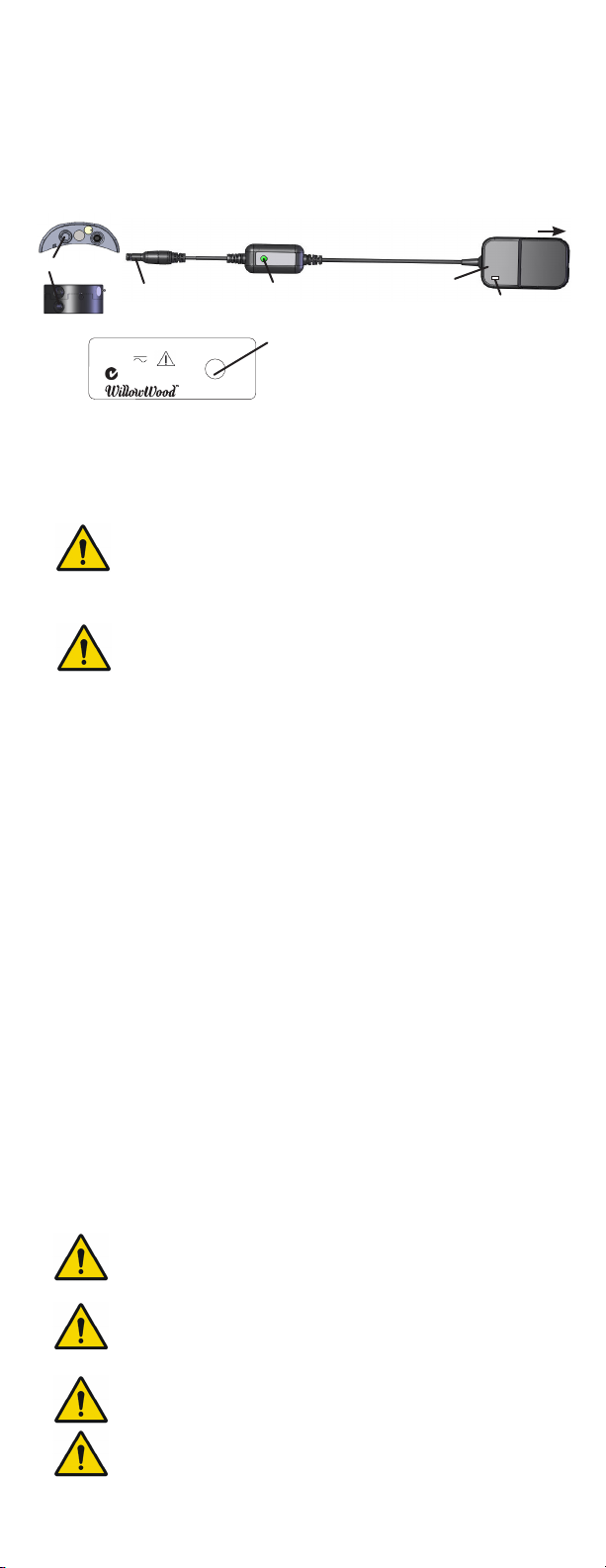
CHARGING THE VACUUM PUMP BATTERY
The Vacuum Pump should be charged before it is used for the
first time, at the end of each day of use, and when the Battery
Indicator on the fob is red.
Vacuum Pump
Charger
To AC outlet
charging port
charging plug
Node LED
Node LED
(indicates Charger function)
RED = fault
SOLID = charging
FLASHING = charged
AC Adapter
Adapter LED
(indicates that
AC outlet is
providing power
to Charger)
1. The Vacuum Pump must be charged in a well-ventilated area
between the temperatures of 5 °C (41 °F) and 32 °C (90 °F).
Charging outside of this range may result in prolonged or
incomplete charging and may damage your Vacuum Pump.
Only charge the Vacuum Pump in a well ventilated
area at a temperature between 5 °C (41°F) and 32°C
(90°F). Charging outside of these conditions may
damage the Vacuum Pump.
A Vacuum Pump enclosed by a cosmetic cover will
retain heat, but in most cases should charge normally
at temperatures below 27°C (80°F). The battery may
not fully charge at higher temperatures.
2. Insert the charging plug all the way into the charging port.
3. Plug the Charger into a power outlet. The Adapter LED will
light. If the Node LED does not light, make sure you have
inserted the charging plug all the way into the port.
If the Node LED is red, reset the Charger by unplugging it
from the wall and plugging it back in.
While charging is in progress, the Node LED will be solid. The
battery indicator on the fob will flash alternately between red
and green.
4. When charging is complete, the Node LED will flash.
Disconnect the Charger from the Vacuum Pump and from
the power outlet.
When you are ready for the pump to begin regulating the
vacuum, either turn on the fob (refer to page 11) or press the
on/o button on the Vacuum Pump. The pump will operate
until the preselected vacuum level is reached.
Note: Your pump can be used while charging. If the pump has
just been unplugged from the Charger, it will be in Standby State
(refer to page 11). To resume vacuum regulation, press the on/o
button one time for Active State. Press again to turn the pump o.
Walking while charging your pump may cause you to trip
and fall. Do NOT walk while your LimbLogic is plugged into
the charger.
Use ONLY a WillowWood Charger. Use of any other charger
may result in damage to the Vacuum Pump or the charger
or both and may negatively aect EMC performance and/
or compliance and may result in serious injury or death.
The charger may pose both a strangulation and/or
electrocution hazard and should not be handled by children.
Do not use the Charger near water. The Charger is
not waterproof. Use of the charger near water may
result in serious injury or death.
9
Overview
Your battery will power your LimbLogic pump for at least a
full 18 hour day of normal usage. It will do so for the life of the
product. (Refer to “Service Life” on page 23.) If it is unable to
do so, please refer to the troubleshooting section or contact
WillowWood.
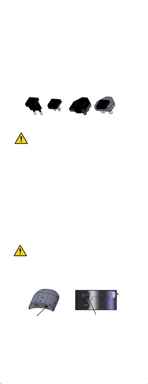
CHARGING THE VACUUM PUMP BATTERY OUTSIDE THE
UNITED STATES
Chargers sold for use outside the U.S. come with a set of prong
adapters. These adapters allow you to use the Charger in many
countries.
Plugging a prong set into an outlet without the
Charger may expose you to dangerous voltages
potentially leading to injury or death. Always
plug the prong set into the Charger before plugging
the Charger or the prong set into an outlet.
CHARGING THE VACUUM PUMP BATTERY IN A VEHICLE
To use a vehicle’s power to charge the Vacuum Pump, you must
purchase a Power Inverter rated at 75 Watts or less to convert the
vehicle’s 12V DC power to 120V AC. An example of an acceptable
Power Inverter is the Digital Concepts™ 75 Watt Portable Power
Inverter (available from general retailers).
1. Plug the Power Inverter into the vehicle’s 12V DC socket.
2. Connect the Charger to the Vacuum Pump.
3. Plug the Charger’s AC Adapter into the Power Inverter’s
three-pronged receptacle.
Do not operate the Charger above 41˚C (105˚F).
The battery may not fully charge at higher temperatures.
TURNING ON THE VACUUM PUMP
on/o button
on/o button
Press the on/o button on the Vacuum Pump one time. The
Vacuum Pump will beep once.
Before turning on the fob as described below, wait 10
seconds for the pump to activate.
10
 Loading...