

WillowWood LIMBLOGIC M Prosthetist Instructions

Prosthetist
Instructions
WHAT'S IN THE BOX
LimbLogic M
Proximal Gasket (2)
M6 X 50 mm Socket Head Capscrews (4)
Split Washer
LimbLogic 4-Hole Adapter
Forming Plate with 4 M6 X 10 mm Capscrews
Poron Filter
Instructions
LimbLogic M Prosthetist Instructions
LimbLogic M Patient Instructions
LimbLogic M Fabrication Instructions
The LimbLogic M is an elevated vacuum suspension system that
operates by compressing with each step and is completely integrated
into the prosthesis without the annoyances of tubes in the socket.
The Ohio Willow Wood Company
15441 Scioto Darby Road
Mt. Sterling, OH 43143
phone 740.869.3377 / 800.848.4930
fax 740.869.4374 www.willowwoodco.com
Ohio Willow Wood Company B.V
Keizersgracht 62/64
1015 CS Amsterdam
The Netherlands
Patent www.willowwoodco.com/
education-and-resources/patents
1
PN-2580-B 19 SEPT 2018

Unauthorized changes or modifications to the pump
or accessories may impair their function resulting in
injury or death, will void the warranty, and may
prevent their compliance with relevant standards.
This pump is only designed to move air; use of
Vaseline® or similar lubricating creams inside the
socket will clog the pump. Do not allow foreign
substances to be pulled through the pump. This may
impair function of your vacuum system.
LimbLogic is designed for use by a single patient only.
Use on more than one patient may result in crosscontamination potentially causing a serious infection.
LimbLogic pumps cannot compensate for failures in
the associated prosthetic socket or sealing system.
Only use LimbLogic pumps with commercially proven
socket and sealing systems. Use with other sealing
systems may result in loss of suspension resulting in
injury or death.
TABLE OF CONTENTS
Page
Patient Criteria ......................................................................................................4
Fitting Instructions .............................................................................................4
Assembly .................................................................................................................5
Rotation Adjustment .........................................................................................6
Stiness Adjustment .........................................................................................7
Vacuum Level Adjustment ..............................................................................9
Patient Briefing ..................................................................................................10
Potential Home Challenges ..........................................................................10
Maintenance.........................................................................................................10
Exposure to Water............................................................................................10
Support ................................................................................................................ 10
Diagnostic Kit ........................................................................................................11
Operation at High Altitude ........................................................................... 13
Service Life ........................................................................................................... 13
Warranty ................................................................................................................ 13
Regulatory Information .................................................................................. 14
User Profile ........................................................................................................... 15
Performance Characteristics ....................................................................... 15
Physical Measurements .................................................................................. 15
2 3
Overview
Overview
PATIENT CRITERIA
Indications
Patients who meet the following criteria should be considered
for this system.
• Patients who are transtibial amputees.
• Patients who comment about lack of suspension or feeling
insecure in their current prosthesis.
• Patients who exhibit high cognitive function and are "in
tune" with prosthetic fit.
• Community ambulators whose activity level is at least
Level 2. (Level 2: The patient has the ability or potential for
ambulation with the ability to traverse low-level environmental barriers such as curbs, stairs or uneven surfaces.
This is typical of the limited community ambulator.)
• Patients who prefer simple non-electrical solutions.
• Patients who could benefit from vertical shock reduction.
Contraindications
Patients with any of the following conditions should not be
considered for this system:
• Patients other than transtibial amputees.
• Patients who require the ability to turn o the vacuum
pump or greatly vary the vacuum level.
• Patients who need an audible indication of a leak in their
system.
• Patients who weigh less than 100 lb (45 kg), because they
will be unable to activate the pump
• Patients who weigh more than 330 lb (150 kg) for
U.S. Acitivity Level K2-K3, or more than 300 lb (135 kg)
for U.S. Activity Level K4.
FITTING INSTRUCTIONS
1. Attach the pump to the prosthesis (refer to page 5).
2. Adjust the spring stiffness (refer to page 7).
3. Adjust the vacuum level if desired (refer to page 9).
• For low vacuum mode, turn the 4 mm hex screw
counterclockwise until it comes to a stop
(approximately 3/4 of a turn). For the lowest
possible vacuum level, increase the spring stiffness.
• To return to high vacuum mode, turn the 4 mm hex
screw clockwise until it comes to a stop
(approximately 3/4 of a turn). For the highest
possible vacuum level, decrease the spring stiffness.
ASSEMBLY
1. Fabricate a laminated socket using the LimbLogic 4-Hole
Adapter. Follow the fabrication instructions provided with
the adapter.
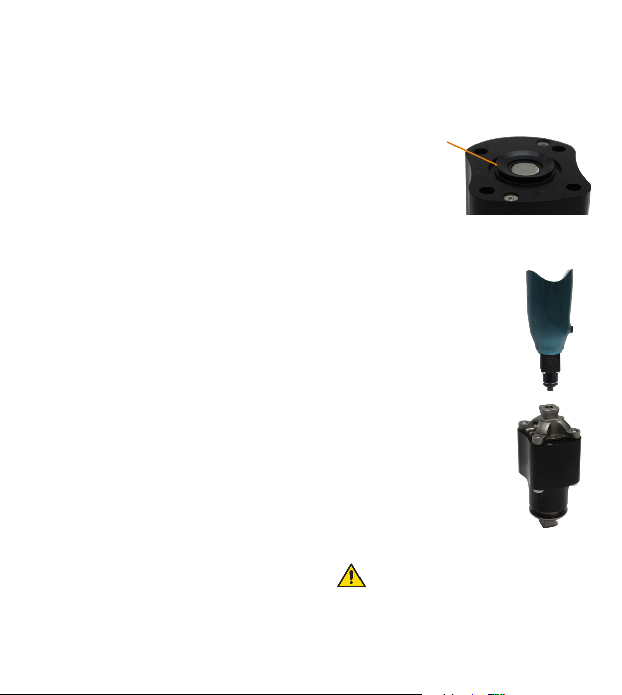
2. Apply the proximal gasket to proximal surface of the
pump.
proximal gasket
You should be able to turn
the pump upside down
without the gasket falling
o. If the gasket falls o,
it was not properly seated
into the recess.
Be sure to fully seat the gasket onto the inlet before
attaching the pump to the socket. Failure to properly
seat the gasket may result in leaks.
3. Using the four M6 x 50 mm
socket head screws provided,
attach the pump to the
socket with the logo facing
anterior.
OR
If the prosthesis requires a hose
barb connection instead of a
direct mount, attach the pump
to a LimbLogic Vacuum Pyramid
(LLV-01044) using the four
M6 x 50 mm socket head
screws provided.
Apply Loctite 242 (or equivalent) and tighten the screws
to 9 ft-lbs (12 Nm).
The proximal end of the pump must be attached to
either the LimbLogic 4-Hole Adapter (LLV-01041) or
to the LimbLogic Vacuum Pyramid (LLV-01044).
4. Install the mating pyramid receiver component of your
choice onto the pyramid at the distal end of the pump.
Once alignment has been achieved, follow the torque and
threadlocker specifications provided by the manufacturer
of the pyramid receiver.
4 5
 Loading...