

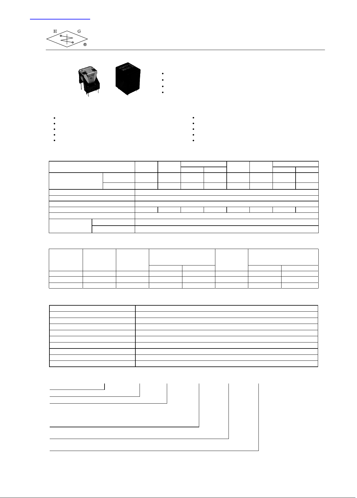
Willow Technologies HG4117 User Manual
查询HG4117供应商
Automotive Subminiature PCB Power Relay
TYPICAL AUTOMOTIVE APPLICATIONS
Flasher
Interval wiper control
Fuel pump control
Anti-theft alarm system
Automatic mirror adjustment
CONTACT DATA
Form
Max. Switching Current
Material
Initial Contact Resistance
Max. Switching Voltage
Max. Continuous Current
Min. Load
Service Life
Mechanical
Electrical
Make
Break
1 Form A
(H)
60A
(S:100A)
20A
15A
HG4117
FEATURES
15A continuous current capacity
Six different contact forms
Available with open, dust cover and sealed version
Automotive-oriented design
Air conditioning
Door lock
ABS
Belt tension adjustment
Power window
1 Form B
(D)
12A
10A
10A 15A 10A 2 x 10A 2 x 7A 2 x 7A 2 x 5A
1 Form C (Z)
NO NC NO NC
60A
(S:100A)
20A
AgNi0.15, AgSnOInO
100 mΩ max. at 0.1A, 6VDC
See curve, current dependent
2 x 10
1 Form U
(SH)
10
7
ops.
2 x 40A
(S:70A)
2 x 20A
12A
10A
0.5A, 5VDC
5
ops, see Note 4
1 Form V
(SD)
2 x 8A
2 x 7A
1 Form W (SZ)
2 x 30A
(S:50A)
2 x 15A
2 x 5A
2 x 5A
COIL DATA
Coil Voltage
Code
006
012
024
Nominal
Voltage
(VDC)
6
12
24
Resistance
(Ω) ±10%
28
130
520
Must Operate Voltage max.
A, B, C, U, V
CHARACTERISTICS
Operate Time
Release Time
Insulation Resistance
Dielectric Strength
Shock Resistance
Vibration Resistance
Drop Resistance
Power Consumption
Ambient Temperature
Weight
3 ms. typical
1.5 ms. typical
100 MΩ, at 500 VDC, 50%RH
500 Vrms, 1 min.
10 g, 11ms.
DA 1.5mm, 20 - 200 Hz, functional
1 M height drop on concrete in final enclosure
1.1 W, approx.
-40ºC to 85ºC operating; -40ºC to 155ºC storage
Open: 8 g; Covered: 12 g, approx.
ORDERING DESIGNATION
Example:
Model
Coil Voltage code
Contact Form
H: 1 Form A ; SH: 1 Form U
D: 1 Form B ; SD: 1 Form V
Z: 1 Form C ; SZ: 1 Form W
Version
Nil: Open; 1: Sealed; 2: Dust Cover
Contact Material
Nil: AgNi10; A: AgNi0.15; C: AgCdO; S: AgSnOInO
HG4117 / 012 - Z 1 A
3.75
7.50
15.00
(VDC)
W
4.5
9.0
18.0
Allowable
Voltage
(VDC)
8
16
31
Must Release Voltage min.
B, V
0.35
0.70
1.40
(VDC)
A, C, U, W
0.7
1.4
2.8
HG4117 1/2
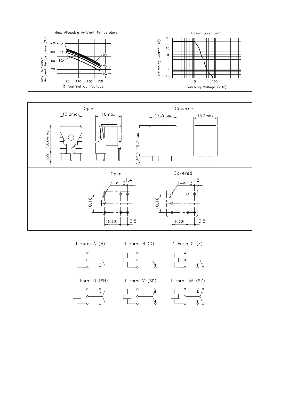
REFERENCE CURVES
OVERALL DIMENSIONS, MOUNTING HOLES AND WIRING DIAGRAMS (mm)
Overall Dimensions
HG4117
Mounting Holes (Bottom View)
Wiring Diagrams (Bottom View)
NOTES
1. All parameters, unless otherwise specified, are measured at ambient temperature 23ºC.
2. Maximum make current refers to inrush current of lamp load.
3. At ambient temperature of 85ºC, maximum allowable voltage should be reduced to 72%.
4. Electrical life obtained at resistive or inductive load at 10A, 15VDC for A, B, C, U, V forms, 7A, 15VDC for W form,
with suitable arc-suppression circuit attached with operating frequency of 1 ops/sec.
5. Custom-made services available with operational quantity. Please let us know your special requirements.
6. Specifications subject to change without prior notice.
Shawlands Court
Newchapel Road
Lingfield
Surrey RH7 6BL
England
Willow Technologies Limited
Tel: +44 (0) 1342 835234
Fax: +44 (0) 1342 834306
email: sales@willow.co.uk
HG4117 2/2
 Loading...