

Willoughby WWF-3603 Installation & Operation Manual
Rev. 11/2016
WWF-3603
Willoughby Industries, Inc.
5105 West 78th Street
Indianapolis, IN 46268
Toll Free: (800) 428-4065
Local: (317) 875-0830
Fax: (317) 875-0837
www.willoughby-ind.com
Installation &
Operation Manual
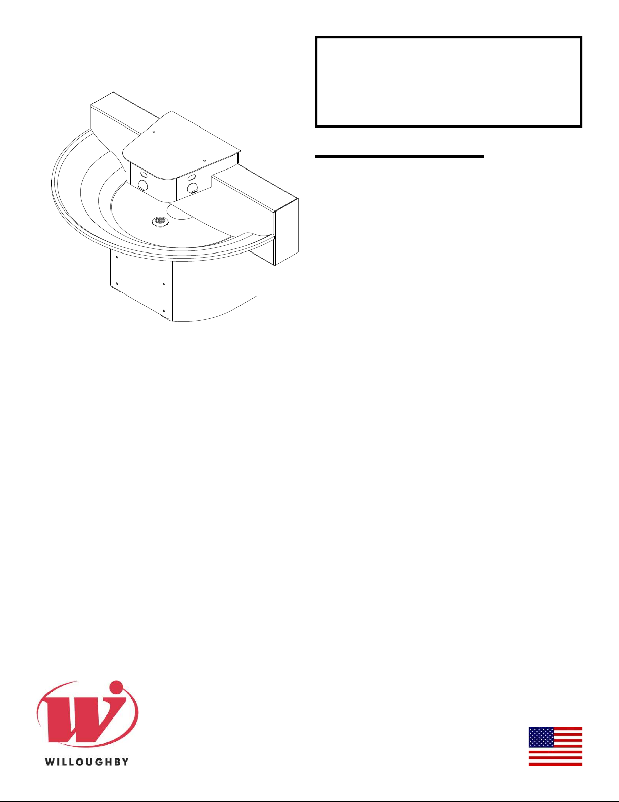
WWF-3603 Series
Three-station 36" 180°
Stainless Steel Washfountain
Electronic/Pneumatic
Table of Contents
Pre-Installation Information .....................................2
Physical / Rough-in Dimensions ............................. 3
Required Installation Supplies ................................4
Parts List ................................................................5
Hardware Identifi cation ..........................................6
Installation Instructions .............................................
Step 1: Pedestal Mounting ................................. 7
Step 2: Drain Assembly .....................................8
Step 3: Head and Basin Assembly ....................9
*WWF-3603 Assembly Drawing ..........10
Step 4A: Connections for Infrared/Piezo
Actuators ........................................... 11
Step 4B: Connections for Pneumatic Actuators
.......................................................................... 12
Step 5: Final Assembly ....................................13
JACO Fitting Instruction ........................................14
Adjustable Mixing Valve Installation .....................15
Infrared Sensor Installation Instructions ............... 16
Pneumatic Valve Operation Details ......................17
Liquid Soap Specifi cation and Maintenance .........18
Care and Maintenance .........................................19
Troubleshooting ........................................................
Infrared Sensors ............................................... 20
Electronic Valves ..............................................21
Pneumatic Valves ............................................. 22
Drawings ...................................................................
General Dimensions and Rough-in Detail ........23
Valve Details .....................................................24
Miscellaneous Details .......................................28
Warranty ............................................................... 32
MADE IN THE U.S.A.
Stainless Steel 180° Washfountain
WWF-3603 Series
Installation & Operation Manual
Pre-Installation Information
Check Rough-In location PRIOR to installation
Flush lines thoroughly PRIOR to hook-up
When installing the Willoughby Industries' WWF-3603 Series washfountain system:
Before Step 1 of the installation instructions, ensure that rough-ins are in the correct location.
The valve assembly, including the spray head, MUST NOT BE connected until after
all lines have been fl ushed to remove the small particles of debris that are inherent
with new construction projects and all chemicals that are used in fl ushing are purged
from the system.
Chemicals used in fl ushing plumbing systems can attack the internal components of
the valve and spray head and severely damage them, so any fl ushing of the system
must be followed by a full fl ushing with pure water to clear any harsh chemicals
remaining in the system. Debris in the system if allowed to enter the valve assembly
and spray head can cause poor performance or outright failure.
Again DO NOT attempt to connect the valve assembly and spray head until after all
fl ushing is complete and pure water is the only media that will be passing through the
system. Damage to the valve assembly or spray head caused by harsh chemicals or
debris will not be covered by the manufacturer's warranty.
Check Rough-In location PRIOR to installation
Flush lines thoroughly PRIOR to hook-up
Willoughby Industries, Inc. TOLL FREE (800) 428-4065 ● LOCAL (317) 875-0830 ● FAX (317) 875-0837
Page 2 www.willoughby-ind.com
Rev. 11/2016
Stainless Steel 180° Washfountain
WWF-3603 Series
Installation & Operation Manual
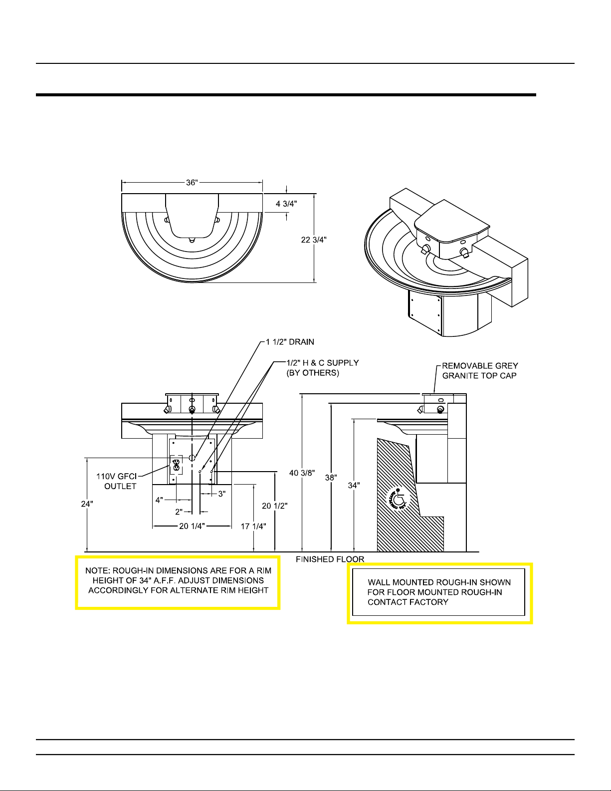
Physical / Rough-in Dimensions- WWF-3603
*WWF-3603 (wall-mounted) unit shown; WWF-3603-FL (fl oor mounted)
will have similar pedestal dimensions, see note below for rough-in.
Willoughby Industries, Inc. TOLL FREE (800) 428-4065 ● LOCAL (317) 875-0830 ● FAX (317) 875-0837
Rev. 11/2016
Page 3www.willoughby-ind.com

Stainless Steel 180° Washfountain
WWF-3603 Series
Required Installation Supplies
• Proper mounting hardware
• Hardware for waste oulet connections
• Gasket for waste outlet connection
• Shims (for installation if necessary)
• Supply piping
• Silicone caulk
• Plumbers putty
Installation & Operation Manual
WARNING: Willoughby Industries does not assume any
responsibility for personal injury or damage to equipment due
to an improperly installed WWF-3603 Series washfountain.
Willoughby Industries, Inc. TOLL FREE (800) 428-4065 ● LOCAL (317) 875-0830 ● FAX (317) 875-0837
Page 4 www.willoughby-ind.com
Rev. 11/2016

Stainless Steel 180° Washfountain
WWF-3603 Series
Installation & Operation Manual
Parts List
DESCRIPTION PART# 3 STATION PART# 4 STATION
DRAIN ASSEMBLY 380283 380283
HARDWARE KIT 800258 800258
PLASTIC VALVE BRACKET 9805013 9805014
VALVE FITTING ASSEMBLY 980600A 980600A
CHECKSTOP ASSEMBLY 980183 980183
STAINLESS STEEL FLEX HOSE (6") 980506 980506
STAINLESS STEEL FLEX HOSE (20") 980520 980520
POWERS HYDROGUARD T/P (LFe480) 700480ELF 700480ELF
SPRAY HEAD AERATOR 320157A 320157A
SOLID SURFACE TOP COVER 800333LP-GG* 800441LP-GG*
36" STAINLESS STEEL BOWL/PEDESTAL WWF-3603 N/A
42" STAINLESS STEEL BOWL/PEDESTAL WWF-4203 WWF-4204
54" STAINLESS STEEL BOWL/PEDESTAL WWF-5403 WWF-5404
36" VALVE HEAD KIT WWF-3603 N/A
42" VALVE HEAD KIT WWF-4203 WWF-4204
54" VALVE HEAD KIT WWF-5403 WWF-5404
*XX REPRESENTS THE WASH FOUNTAIN TOP COVER COLOR
GRAY GRANITE=GG
STAINLESS STEEL=S/S
Willoughby Industries, Inc. TOLL FREE (800) 428-4065 ● LOCAL (317) 875-0830 ● FAX (317) 875-0837
Rev. 11/2016
Page 5www.willoughby-ind.com
Stainless Steel 180° Washfountain
WWF-3603 Series
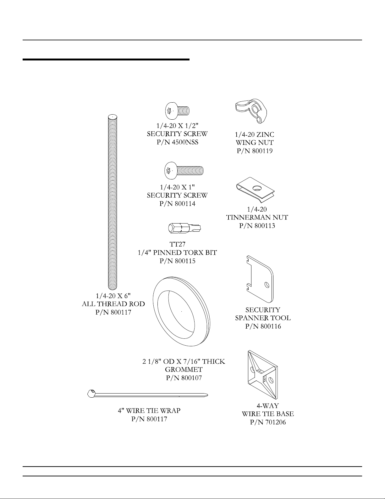
Hardware Identifi cation
Installation & Operation Manual
Willoughby Industries, Inc. TOLL FREE (800) 428-4065 ● LOCAL (317) 875-0830 ● FAX (317) 875-0837
Page 6 www.willoughby-ind.com
Rev. 11/2016

Stainless Steel 180° Washfountain
WWF-3603 Series
Installation & Operation Manual
Installation Instructions
Step 1: Pedestal Mounting*
Parts supplied:
• Pedestal/Basin/Backsplash assembly (pre-assembled)
Note: Hardware for wall anchoring by others
*For details on Step 1 instructions, see WWF-3603 Assembly Drawing on Page 10
1.) Unpack Pedestal/Basin/Backsplash assembly and inspect parts.
2.) Place included rough-in template at the desired position and mark anchor holes.
Make sure that the intended anchor locations will provide adequate backing to support the
installed washfountain. If adequate backing does not exist, install appropriate support backing
or relocate unit before proceeding with installation (backing provided by others).
3.) Secure the included Z-clips using anchors that are adequate for the type of wall
(anchors by others).
4.) With assistance, lift the assembly over and carefully fi t into the previously installed Z-clips.
5.) Align the frame mounting holes on the lower section of the assembly with the anchor holes
marked in Step 2. Secure the assembly to the wall using anchors that are adequate for the
type of wall (anchors by others).
Willoughby Industries, Inc. TOLL FREE (800) 428-4065 ● LOCAL (317) 875-0830 ● FAX (317) 875-0837
Rev. 11/2016
Page 7www.willoughby-ind.com

Stainless Steel 180° Washfountain
WWF-3603 Series
Installation Instructions (cont.)
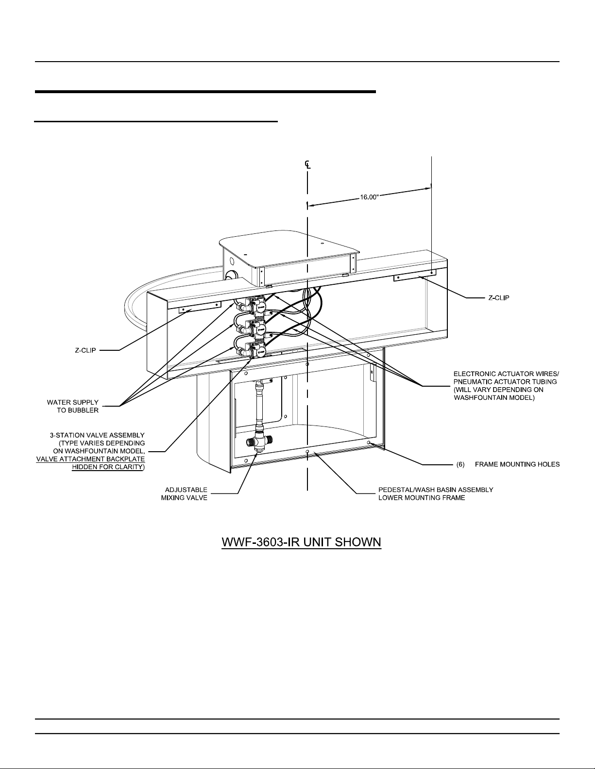
Step 2: Drain Assembly
Parts supplied:
• Pedestal/Basin/Backsplash assembly (pre-assembled)
• Drain assembly (see diagram)
1.) Insert the drain assembly down through the basin drain hole.
2.) Secure in place by fi tting the rubber washer onto the drain
assembly from the underside of the basin and tightening the
locknut onto the drain assembly, sandwiching the washer
between the basin and locknut.
Installation & Operation Manual
Note: Over-tightening can damage the basin and/or
drain assembly components
Willoughby Industries, Inc. TOLL FREE (800) 428-4065 ● LOCAL (317) 875-0830 ● FAX (317) 875-0837
Page 8 www.willoughby-ind.com
Rev. 11/2016
Stainless Steel 180° Washfountain
WWF-3603 Series
Installation Instructions (cont.)
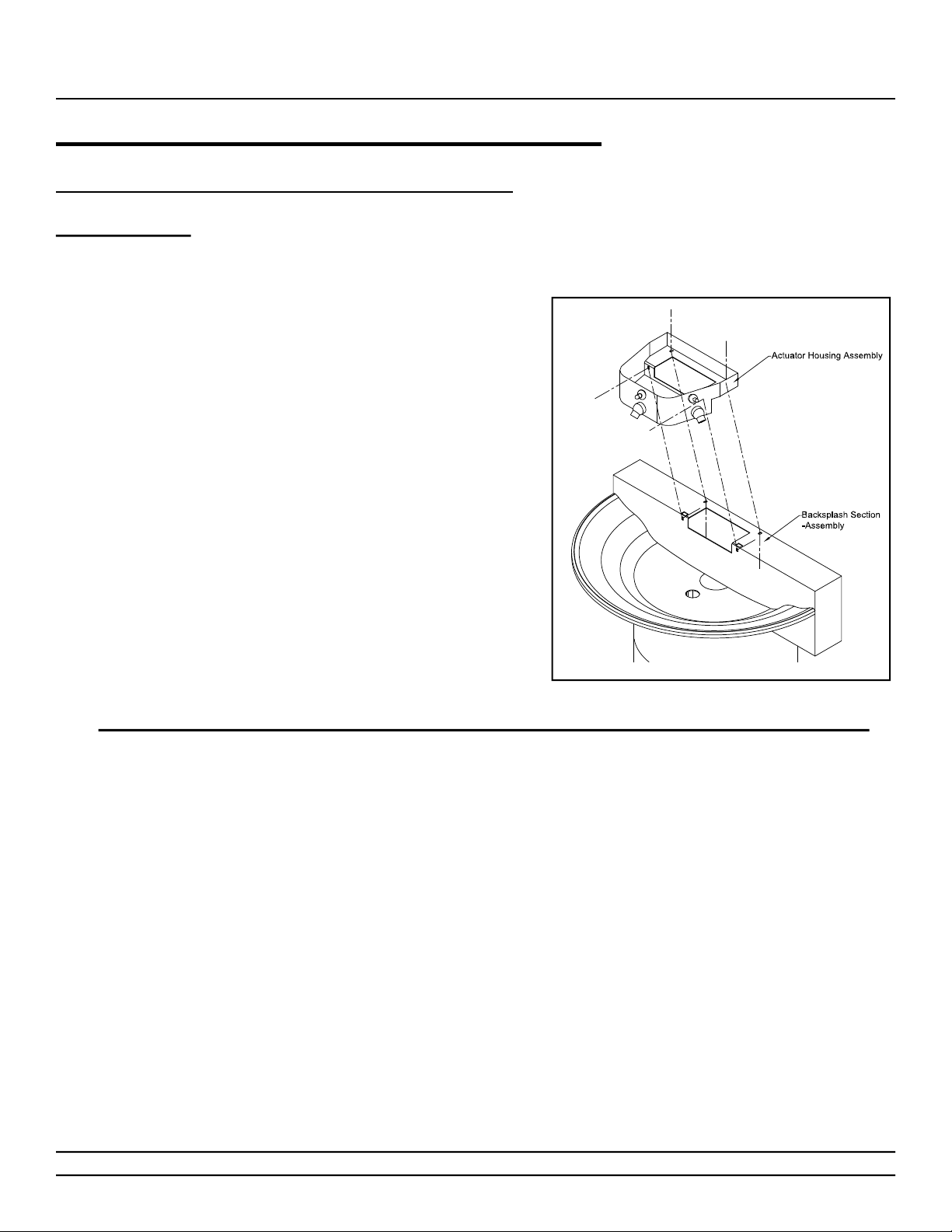
Step 3: Valving and Basin Assembly*
Parts supplied:
• Pedestal/Basin/Backsplash assembly (pre-assembled)
• Actuator housing assembly
• 1/4"-20 X 1/2" security screws
• 1/4-20 tinnerman nuts
Caution: Do not leave the pedestal/wash basin
assembly unsupported, as it may fall
and cause damage or personal injury.
Installation & Operation Manual
*For details on Step 3 instructions, see WWF-3603 Assembly Drawing on Page 10
1.) Place the actuator housing assembly over the top center of the backsplash, aligning like
mounting holes accordingly. Secure with security screws and tinnerman nuts.
2.) The wash basin is ready for plumbing and/or electrical installation**.
**If you have infrared sensors or electrical pushbuttons, go to Step 4A.
If you have pneumatic pushbuttons, go to Step 4B.
Willoughby Industries, Inc. TOLL FREE (800) 428-4065 ● LOCAL (317) 875-0830 ● FAX (317) 875-0837
Rev. 11/2016
Page 9www.willoughby-ind.com
Stainless Steel 180° Washfountain
WWF-3603 Series
Installation Instructions (cont.)
*WWF-3603 Assembly Drawing
Installation & Operation Manual
Willoughby Industries, Inc. TOLL FREE (800) 428-4065 ● LOCAL (317) 875-0830 ● FAX (317) 875-0837
Page 10 www.willoughby-ind.com
Rev. 11/2016
 Loading...