

Willoughby E1L1, E1L2 Installation & Operation Manual
Material:
2 Of 3
Part Number:
E1L11
2 Places +/- �03
3 Places +/- �015
Fractions +/- 1/32"
B
Willoughby Industries Inc.
Indianapolis, Indiana
Sheet:
Tolerances
Except as
N/A
Noted
Date:
Title or Part Description:
Drawing #:
Revision #:
E1L11 SINGLE TEMP ELECTRONIC VALVE ASSEMBLY O&M PAGE 2 ISO
TRB
STANDARD DWG�
980576
Job Name:
3/15/11
Drawn By:
N/A
Scale:
1:8
Qty:
Angle +/- 1
11/13/12
3
2
1
5 6
7
4
8
9
10
OPTIONAL 3/8" x 3/8" ELBOW
8
10
7
8
6
1
10
11
5
4
3
2
9
OPTIONAL 3/8" x 3/8"
ELBOW
N/A
2 Places +/- �03
3 Places +/- �015
Fractions +/- 1/32"
Title or Part Description:
Material:
N/A
Job Name:
Drawn By:
Date:
Revision #:
E1L21 DUAL TEMP ELECTRONIC VALVE ASSEMBLY O&M PAGE 4 ISO
TRB
Drawing #:
A
980610
Approved By:
Part Number:
E1L21
5/1/12
Scale:
1:8
Qty:
Sheet:
2 Of 3
Angle +/- 1
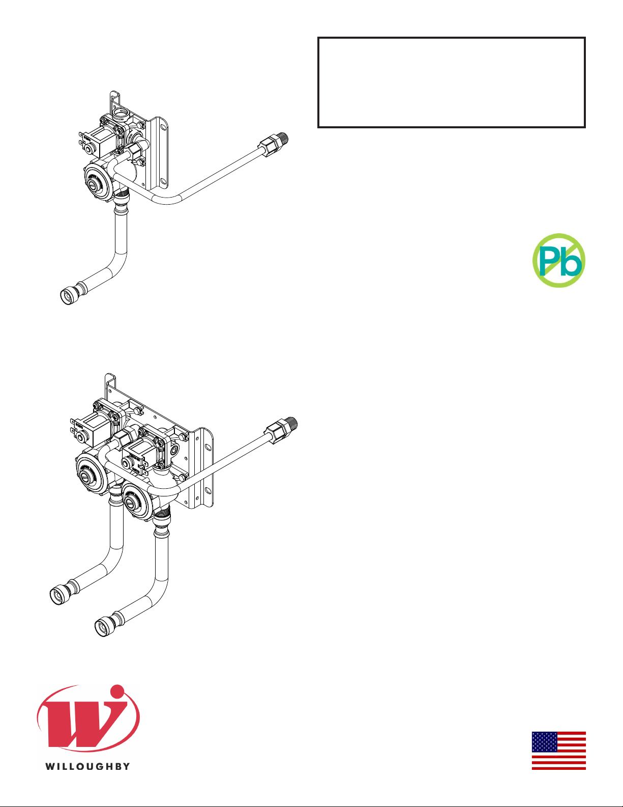
Installation &
Operation Manual
E1L1 and E1L2
Lead-Free Electronic Series
Valves
(Plastic Bodied)
Table of Contents
Pre-Installation Information �������������������������������������3
General Specications ��������������������������������������������4
E1L1
E1L2
Physical Dimensions ������������������������������������������������
E1L1 Single Temp Solenoid Valve Assembly
#980408 �������������������������������������������������������������� 5
E1L11 Valve Breakdown �������������������������������������6
E1L12 Manifold Valve Breakdown ���������������������� 7
E1L21 Valve Breakdown������������������������������������� 8
E1L22 Manifold Valve Breakdown ���������������������� 9
Checking Contents ����������������������������������������������� 11
Installation Instructions ����������������������������������������� 12
Electronic Piezo Switch Detail �������������������������� 13
Jaco Fitting Instructions ������������������������������������ 14
Care and Maintenance ���������������������������������������������
Electronic Valve Assembly Operation and
Maintenance ����������������������������������������������������� 15
Cleaning Instructions ���������������������������������������� 16
Troubleshooting Electronic Valves �����������������������17
Replacement Part Numbers �������������������������������������
E1L1 Single Temp Solenoid Valve Assembly
#980408 ������������������������������������������������������������ 18
Checkstop Breakdown P/N 980183 ������������������19
Drawings ������������������������������������������������������������������
Pushbutton Assembly #600313 ������������������������ 20
Pushbutton Assembly #600314LR ������������������� 21
Warranty ���������������������������������������������������������������22
Rev. 6/2019
Willoughby Industries, Inc.
5105 West 78th Street
Indianapolis, IN 46268
Toll Free: (800) 428-4065
Local: (317) 875-0830
Fax: (317) 875-0837
www.willoughby-ind.com
MADE IN THE U.S.A.

E1L1 and E1L2
Electronic Series Valves
(Page left intentionally blank)
Installation & Operation Manual
Willoughby Industries, Inc. TOLL FREE (800) 428-4065 ● LOCAL (317) 875-0830 ● FAX (317) 875-0837
Page 2www.willoughby-ind.comRev. 6/2019

E1L1 and E1L2
INSTALLATION INSTRUCTIONS
Installation notice!
INSTALLATION INSTRUCTIONS
Installation notice!
Electronic Series Valves
Installation & Operation Manual
Pre-Installation Information
Check Rough-In location PRIOR to installation
Flush lines thoroughly PRIOR to hook-up
When installing the Willoughby Industries' E1L1 and E1L2 Lead-free Electronic Series Valves:
Before step 1 of the installation instructions, ensure that rough-ins are in the correct location�
The valve assembly, including the spray head, MUST NOT BE connected until after
all lines have been ushed to remove the small particles of debris that are inherent
with new construction projects and all chemicals that are used in ushing are purged
from the system�
Chemicals used in ushing plumbing systems can attack the internal components of
the valve and spray head and severely damage them, so any ushing of the system
must be followed by a full ushing with pure water to clear any harsh chemicals
remaining in the system� Debris in the system if allowed to enter the valve assembly
and spray head can cause poor performance or outright failure�
Again DO NOT attempt to connect the valve assembly and spray head until after all
ushing is complete and pure water is the only media that will be passing through the
system� Damage to the valve assembly or spray head caused by harsh chemicals or
debris will not be covered by the manufacturer's warranty�
Check Rough-In location PRIOR to installation
Flush lines thoroughly PRIOR to hook-up
Willoughby Industries, Inc. TOLL FREE (800) 428-4065 ● LOCAL (317) 875-0830 ● FAX (317) 875-0837
Page 3www.willoughby-ind.comRev. 6/2019

E1L1 and E1L2
Electronic Series Valves
Installation & Operation Manual
General Specications
Electronic valve assembly shall be Willoughby Model No� E1L1 or E1L2 as noted� Valve shall be constructed of plastic and stainless steel materials and complies with NSF-61 standard�
Stainless steel pushbutton switches on the xture shall be wired to an appropriate electronic valve
control (select from the list of control choices)� The vandalproof pushbuttons shall be keyed and
non-removable from the front of the xture. The pushbuttons shall require less than 5 lbs. of force to
operate�
The single temperature solenoid valve assembly shall include a stainless steel screwdriver stop and
an integral mounting bracket. Replaceable stainless steel strainer and optional 0.5 GPM ow
control shall be eld serviceable. The connection to the ller/bubbler/showerhead shall be 3/8" O.D.
exible tubing. The water inlet shall be 1/2" FPT (S/S exible supply line) and shall be reversible for
either top or bottom supply� Valve assembly shall be accessible from the pipe chase only�
Flexible tubing shall be supplied for walls up to 8 inches thick� Recommended operating pressure
shall be 35-70 psi� The valve shall withstand pressures up to 90 psi� Cost reducing manifolded
valves shall consist of multiple valve assemblies served by a common supply line� A 24 volt AC
source shall be required for timer and valve operation.
Willoughby Industries, Inc. TOLL FREE (800) 428-4065 ● LOCAL (317) 875-0830 ● FAX (317) 875-0837
Page 4www.willoughby-ind.comRev. 6/2019
E1L1 and E1L2
3 Places +/- �015
3/15/11
Willoughby Industries Inc.
Indianapolis, Indiana
Tolerances
Except as
Title or Part Description:
Material:
Drawn By:
Date:
Revision #:
Drawing #:
Fractions +/- 1/32"
Approved By:
TRB
Sheet:
980408
Job Name:
Part Number:
N/A
Scale:
Qty:
E1L VALVE ASSEMBLY
1 Of 1
E
Noted
2 Places +/- �03
Angle +/- 1
ITEM # SUB-ASSY# PART # DESCRIPTION QTY�
WILLOUGHBY
Electronic Series Valves
Installation & Operation Manual
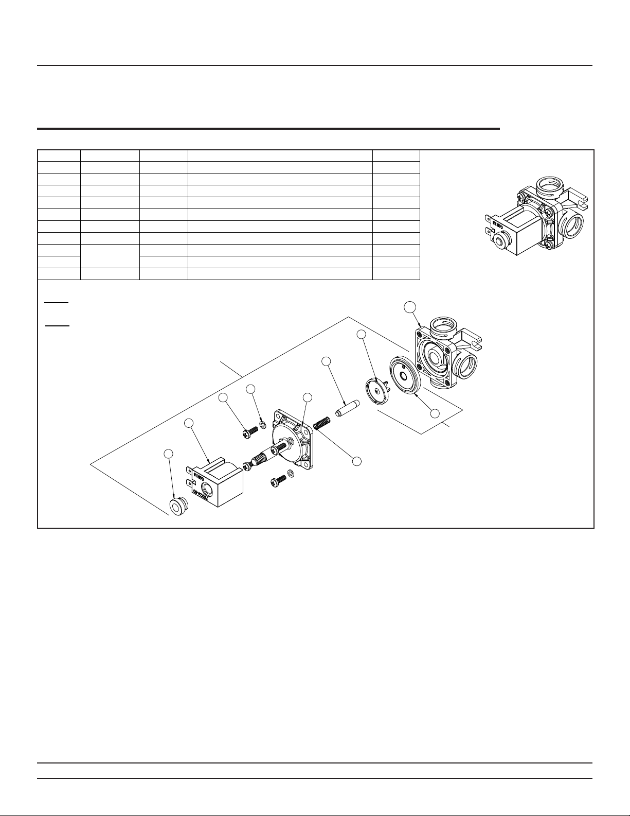
Physical Dimensions
E1L1 Single Temp Solenoid Valve Assembly #980408
1 N/A 980534 NYLON NUT, 5/16-18 1
2 N/A 980532 COIL, 24V DC 1
3 N/A 980170 #8-32 x 1/2 " SCREW 4
4 N/A 980002 SPLIT LOCK WASHER 4
5 N/A 980530 ARMATURE CAP, 24v VALVE 1
6 N/A 980533 SPRING, 5/8 24v VALVE 1
7 N/A 980565 ARMATURE BUMPER ASSEMBLY, EL VALVE 1
8
9 980129 WATER SIDE DIAPHRAGM 1
10 N/A 980420 SINGLE TEMP BASE W/INSERTS 1
NOTE:
NOTE:
980305
REPAIR KIT ORDERING #'S ARE
LISTED IN THE EXPLODED VIEW�
PARTS LISTED IN THE PVK REPAIR
KITS ARE NOT SOLD INDIVIDUALLY
980128 3 PRONGED INSERT 1
10
8
ASSEMBLED VIEW
(1-9) PLUS (*) BELOW
EVK-4 KIT
2
1
4
3
7
5
6
* EVK-4 KIT INCLUDES
380897 VALVE SEAT W/ 0-RING (NOT SHOWN)
9
PVK-3
(8,9)
Willoughby Industries, Inc. TOLL FREE (800) 428-4065 ● LOCAL (317) 875-0830 ● FAX (317) 875-0837
Page 5www.willoughby-ind.comRev. 6/2019
E1L1 and E1L2
Material:
2 Of 3
Part Number:
E1L11
2 Places +/- �03
3 Places +/- �015
Fractions +/- 1/32"
B
Willoughby Industries Inc.
Indianapolis, Indiana
Sheet:
Tolerances
Except as
N/A
Noted
Date:
Title or Part Description:
Drawing #:
Revision #:
E1L11 SINGLE TEMP ELECTRONIC VALVE ASSEMBLY O&M PAGE 2 ISO
TRB
STANDARD DWG�
980576
Job Name:
3/15/11
Drawn By:
N/A
Scale:
1:8
Qty:
Angle +/- 1
11/13/12
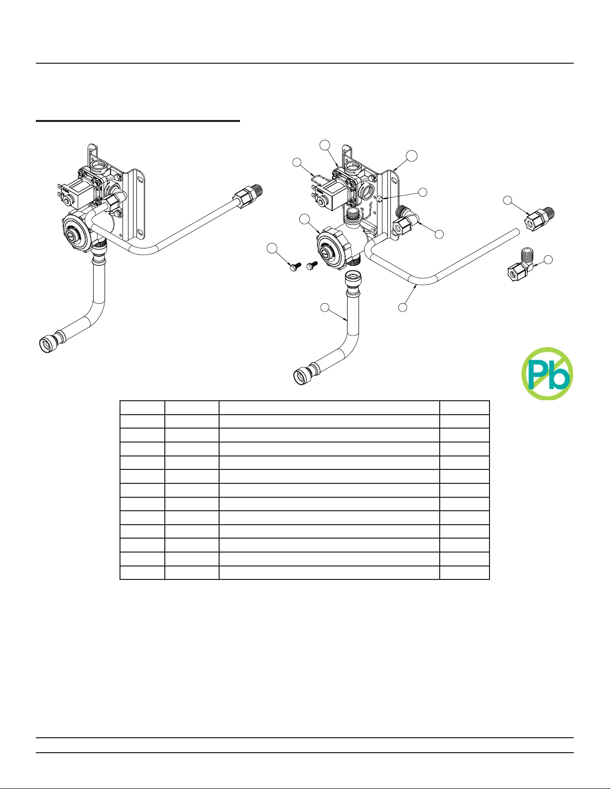
Electronic Series Valves
Physical Dimensions
E1L11 Valve Breakdown
Installation & Operation Manual
1
2
10
ITEM NO� PART # DESCRIPTION QTY
9
3
7
4
OPTIONAL 3/8" x 3/8" ELBOW
5 6
1 980408PR E1L VALVE ASSEMBLY, RIGHT-PLUGGED PORT 1
2 980140 SPRING CLIP 2
3 980183 CHECKSTOP ASSEMBLY 1
4 800133 #10-16 SELF TAP TYPE B HEX HEAD SCREW 4
5 980506 (OPTIONAL) 6" STAINLESS STEEL FLEX HOSE 1
5 980520 (OPTIONAL) 20" STAINLESS STEEL FLEX HOSE 1
6 600523 FLEXIBLE TUBING 3/8" (10mm) O�D� 20 FT� TOTAL PERFOOT
7 980600A VALVE FITTING ASSEMBLY, 3/8" ELBOW 1
8 320566 (OPTIONAL) CONNECTOR, 3/8" TUBE x 3/8" MPT 1
8 320577 (OPTIONAL) ELBOW, 3/8" TUBE x 3/8" MPT 1
9 380138 FLOW CONTROL 0�5 GPM (RED) 1
10 980501 PM1 VALVE BRACKET 1
8
8
Willoughby Industries, Inc. TOLL FREE (800) 428-4065 ● LOCAL (317) 875-0830 ● FAX (317) 875-0837
Page 6www.willoughby-ind.comRev. 6/2019
E1L1 and E1L2
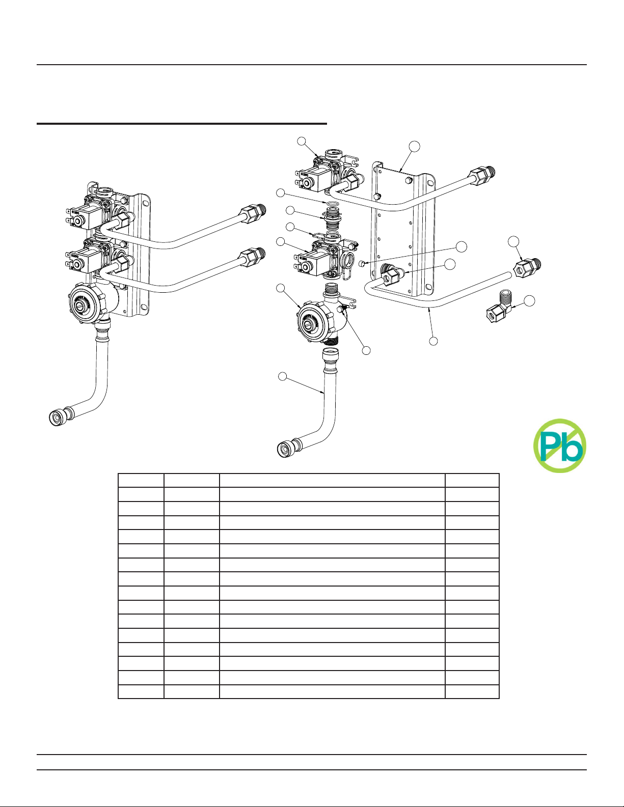
Electronic Series Valves
Physical Dimensions
E1L12 Manifold Valve Breakdown
Installation & Operation Manual
1
2
3
4
6
8
7
13
12
11
OPTIONAL 3/8" x 3/8" ELBOW
9
105
10
ITEM NO� PART # DESCRIPTION QTY
1 980408PR E1L VALVE ASSEMBLY, RIGHT-PLUGGED PORT 1
2 980164 'O'-RING, #015 2
3 980197 PLASTIC VALVE COUPLING 1
4 980140 SPRING CLIP 5
5 980408 E1L VALVE ASSEMBLY 1
6 980183 CHECKSTOP ASSEMBLY 1
7 980506 (OPTIONAL) 6" STAINLESS STEEL FLEX HOSE 1
7 980520 (OPTIONAL) 20" STAINLESS STEEL FLEX HOSE 1
8 800133 #10-16 SELF TAP TYPE B HEX HEAD SCREW 6
9 600523 FLEXIBLE TUBING 3/8" (10mm) O�D� 20 FT� TOTAL PER FOOT
10 320566 (OPTIONAL) CONNECTOR, 3/8" TUBE x 3/8" MPT 2
10 320577 (OPTIONAL) ELBOW, 3/8" TUBE x 3/8" MPT 2
11 980600A VALVE FITTING ASSEMBLY, 3/8" ELBOW 2
12 380138 FLOW CONTROL 0�5 GPM (RED) 2
13 9805012 PM1-MA2 VALVE BRACKET-PLASTIC 1
Willoughby Industries, Inc. TOLL FREE (800) 428-4065 ● LOCAL (317) 875-0830 ● FAX (317) 875-0837
Page 7www.willoughby-ind.comRev. 6/2019
 Loading...