

Willis Electric ZW1101 User Manual
ZW1101 Door Window Sensor
FCC/IC
Fede ra l Co mmunicati on s Co mmission (FCC ) St atement
FCC Ca ut io n: Any changes o r mo di fications not ex pr essly approve d by t he p arty respon si bl e for
comp li an ce could void t he u se r ’s aut ho ri ty to operate t hi s eq uipment.
This d ev ic e complies wi th P ar t 15 of the FCC Rules . Op er ation is subj ec t to t he followin g tw o
cond it io ns: (1) This device may n ot c au se harmful in te rf erence, and ( 2) t hi s device must acc ep t any
inte rf er ence receiv ed , in cluding inter fe rence that may ca us e un desired ope ra ti on.
NOTE : This equ ip ment has been tes te d an d found to comp ly w it h the limits fo r a Cl as s B digital devic e,
purs ua nt t o Part 15 of the FCC Ru le s. The se l imits are des ig ne d to provide re as on able protec ti on
agai ns t ha rmful inter fe re nce in a resident ia l installatio n. Thi s eq ui pment gener at es , uses and can
radi at e ra dio frequen cy e ne rgy and, if not ins ta lled and used in ac co rd ance with the i ns tr uctions,
may ca us h ar mful interfer en ce to radio commu ni ca tions.How ev er, t here is no guar an te e that
inte rf er ence will not o cc ur i n a particular in st allation. If th is e qu ipment does c au se h armful inte rf er ence
to rad io o r te levision re ce pt ion, which can be d et ermined by turn in g th e equipment o ff and o n,
the us er i s en couraged to try t o co rrect the inter fe re nce by one or mor e of t he f ollowing me as ur es:
Reor ie nt o r relocate th e re ce iving antenna .I ncrease the sep ar at ion between t he e qu ipment and
rece iv er. Connect the e qu ip ment into an outl et o n a circuit different f ro m th at to which the rec ei ver
is con ne ct ed.Consul t th e de aler or an experi en ced radio/TV te ch ni cian for help .T hi s equipment
shou ld b e in stalled and o pe ra ted with minimu m di stance 20cm bet we en the radiator a nd y ou r body.
IC Cau ti on :
This d ev ic e complies wi th I nd ustry Canada li ce nce-exempt RS S st an dard(s). Op er at ion is subjec t
to the f ol lo wing two cond it io ns: (1) this devi ce m ay n ot cause inte rf er ence, and (2) t hi s de vice must
acce pt a ny i nterferen ce , in cluding inter fe rence that may ca us e un desired
oper at io n of the device .
DECL AR ATION D E CO NF ORMITE D'IN DU ST RIE CANADA
Ce pér ip hé rique a été tes té e t re connu conform e au x limites spéci fié es d ans RSS-210 .
Son ut il is ation est sou mi se a ux deux conditi on s suivantes :
(1) il n e do it p as provoque r d' in terférences g ên antes et
(2) il d oi t to lérer les inter fé rences re.ues , no ta mment celle ss us ceptibles d 'e n pe rturber le fo nc ti onnement.
WARRANTY
Show H om e Pr oducts warr an ts t his product to be f re e fr om manufact ur in g defects for
a peri od o f tw o years from the or ig inal date of cons um er purchase. This war ra nt y is limited
to the r ep ai r or replacem en t of t his product onl y an d do es not extend t o co ns equential o r
inci de nt al damage to ot he r pr oducts that may b e us ed with this prod uc t.
This w ar ra nty is in lieu of all o th er warranties , ex pr essed or impl ie d. S ome states do n ot
allo w li mi tations on ho w lo ng a n implied war ra nt y lasts or permit t he e xc lusion or lim it at ion
of inc id en tal or conseq ue nt ial damage, so th e ab ove limitatio ns m ay n ot apply to you .
This w ar ra nty gives you spe ci fic rights, and yo u ma y al so have other r ig ht s which vary fr om
stat e to s ta te. if the unit sho ul d prove defecti ve w it hin the warra nt y pe riod.
WARNING
Door window sensor
SPECIFICATIONS
Mode l: ZW 110 1
Powe r su pp ly: battery ER1 42 50, 1/2AA, 3V.
Sign al ( Fr equency): 9 08 .4 2 MHz.
Oper at in g Range: Up to 10 0 fe et l ine of sight
Oper at in g Temp .: - 15°C~60°C (5° F ~1 40 °F)
Wire le ss C ontroller a nd t he c losest Z-Wav e
rece iv er m odule.
Spec ifi ca tions subje ct t o ch ange without no ti ce
due to c on ti nuing produ ct i mp rovement
Website www.i sh owlights.co m
RISK O F FI RE
RISK O F EL EC TRICAL SHO CK
RISK O F BU RN S
CONT RO LL ING APPLIANCES :
EXER CI SE E XTREME CAUTIO N WH EN USING Z-WAVE
DEVI CE S TO CONTROL APPLIANCES. OP ER ATI ON
OF THE Z-WAVE DEVI CE M AY BE IN A DIFF ER EN T
ROOM THAN THE CONTRO LL ED AP PLIANCE, ALS O AN
UNIN TE NT IONAL ACT IVATION MAY OC CU R IF T HE W RO NG
BUTTON ON THE REMOTE I S PR ES SED. Z-WAVE DEVIC ES
MAY AUTOM ATICALLY BE POWERED ON D UE TO TIM ED
EVEN T PROGRA MM IN G. DEPENDIN G UP ON T HE AP PL IANCE , THESE UN ATTEN DE D OR U NINTENTIO NA L OPERATIONS COUL D PO SS IBLY RESU LT IN A HAZARDOUS
COND IT IO N. FOR THE SE REASONS, W E RE CO MMEND
DO NOT RETURN THIS PRO DU CT TO T HE S TORE
THE FO LL OW ING:
DO NOT USE Z-WAVE DE VI CE S TO CONTR OL ELECTRIC
HEATERS OR ANY OTHER APPL IA NC ES WHICH MAY PR ES ENT A HAZARD OU S CO NDITION DUE TO U NATTE NDED OR
UNIN TE NT IONAL OR AU TOMATIC POWER O N CO NT ROL.
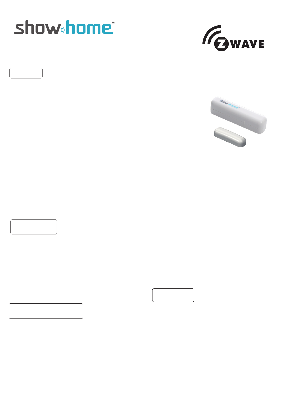
Product Introduction and descrip tio n
Thanks for choosing the show hom e wirel ess doo r/win dow sen sor of the home security dev ice.T his sen sor is a Z- Wave ™ enabl ed
device (interoperab le, two -way RF m esh net worki ng tech nology) and is fully compa tible w ith any Z -Wav e™ enab led net work.
Every mains powered Z-Wave en abled d evice a cts as a si gnal re peater and multiple devi ces res ult in mo re poss ible tr ansmi ssion
routes which helps elim inate “ RF dead -spor ts”Z- Wave ™ enabl ed devices displaying th e Z-Wa ve™ log o can als o be used w ith it
regardless of the manuf actur er, and ou rs can al so be use d in othe r manufacturer’s Z-Wave™ e nable d netwo rks. This s ensor
monitors door/windo w and sen d Z-Wa ve™ sig nal whe n door or w indow is opened and closed .
Operation
Notice: If you install the ent ire Z-Wave™ s ystem f or the fir st time , pleas e refer to the installation guide o f Z-Wa ve™
Inte rface Controller befor e insta lling Z W1101.
1. Unscrew the screw fastening t he rear c over.
2. Slide the rear cover dow n.
3. Using the screws or adhe sive ta pe to affix th e rear co ver on th e frame a long the opening edge of doo r / windo w.
4. Insert a CR123A battery into the b atter y compa rtmen t and LED w ill sta rt to flash slowly,which means t he sens or has
not ye t been added.
5. For adding to a network: Put the Z- Wave ™ Inter face Co ntrol ler int o adding mode, and followi ng its
instruction to add the ZW1101 to your c ontro ller. To get in th e addin g mode, t he distance between sens or and co ntrol ler
is suggested to be in one meter. Pres s the pro gram sw itch of Z W1101 for 1 se cond at l east.The LED on the ZW1101 shou ld go
solid, if not, please try again. For rem oving f rom a net work: P ut the Z- Wave ™ Interface Controller i nto
removing mode, and following i ts inst ructi on to del ete the Z W1101 from your controller. Press the p rogra m switc h of ZW1101
for 1 se cond at least to be removed. For “As socia tion” : remov ing the c over of the ZW1101 to get into the “Awa ke” mod e,
then put the Z-Wave™ Interface Contr oller i nto “As socia tion” , and fol lowing its instruction t o assoc iate th e ZW1101 wit h other
device. Close the cover back aft er “ass ociat ion” do ne, aft erwar d the ZW1101 will get into “Sleep ” mode fo r power s aving .
Support one association grou p (5 node s).”Awa ke” mod e: it is to l eave the “Sleep” mode by rem oving t he cove r of ZW1101, t o
allow the Z-Wave™ Interface C ontro ller to d o “add” , “remo ve”, “A ssoci ation” and to reply and rece ive the c omman ds
from c ontroller.
6. Slide back the rear cove r and scr ew fast ening w ith the f ront co ver, the L ED should go off.
7. Fix the Magnet by using the adhes ive tap e or fixin g screw s, loca te the Ma gnet close to the ZW1101 sensor t he dist ance
between these two devices shou ld be in 1. 9cm.
8. External Switch: If your wind ow need s two sen sors fo r fully m onito ring. You could use an ex terna l switc h to conn ect wit h
the ZW 1101 for extending detectio n. The ZW1101 ha s 2 norma lly clo sed con tact terminals. These can be u sed for
additional external s witch w ired co ntact s. The exte rnal sw itch will send an alarm repo rt (typ e:01, level :11) by open ing
the window/door.
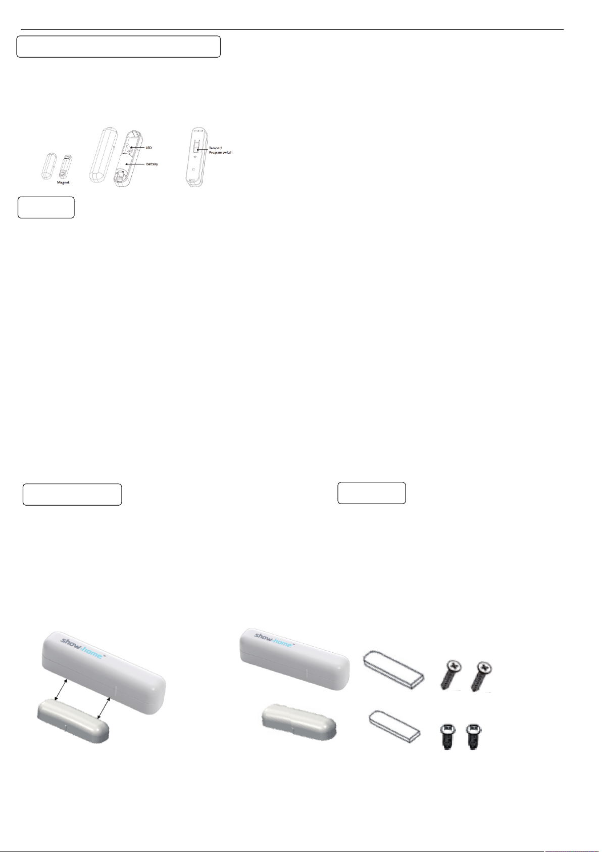
Package content:
ZW1101 Sensor-1pcs
Bracket for Contact Magnet-1 pcs
Magnet-1pcs
Adhesive tape for Magne t /sens or-2p cs
CR14250 3.0V Battery- 1pcs
Screws for bracket/ sensor-4 pcs
Installation Operation man ual-1 pcs
fig1
Assemble
Step1.The magnet shal l be fix ed to c los e
to the specific area,and the dista nce
from sensor shall not be over 1.9cm .
Step2.Fixed with adhe siv e tap o r Scr ews .
.
fig2
 Loading...