

ZW1105 Shock Sensor
FCC/IC
Fede ra l Co mmunicati on s Co mmission (FCC ) St atement
FCC Ca ut io n: Any changes o r mo di fications not ex pr essly approve d by t he p arty respon si bl e for
comp li an ce could void t he u se r ’s aut ho ri ty to operate t hi s eq uipment.
This d ev ic e complies wi th P ar t 15 of the FCC Rules . Op er ation is subj ec t to t he followin g tw o
cond it io ns: (1) This device may n ot c au se harmful in te rf erence, and ( 2) t hi s device must acc ep t any
inte rf er ence receiv ed , in cluding inter fe rence that may ca us e un desired ope ra ti on.
NOTE : This equ ip ment has been tes te d an d found to comp ly w it h the limits fo r a Cl as s B digital devic e,
purs ua nt t o Part 15 of the FCC Ru le s. The se l imits are des ig ne d to provide re as on able protec ti on
agai ns t ha rmful inter fe re nce in a resident ia l installatio n. Thi s eq ui pment gener at es , uses and can
radi at e ra dio frequen cy e ne rgy and, if not ins ta lled and used in ac co rd ance with the i ns tr uctions,
may ca us h ar mful interfer en ce to radio commu ni ca tions.How ev er, t here is no guar an te e that
inte rf er ence will not o cc ur i n a particular in st allation. If th is e qu ipment does c au se h armful inte rf er ence
to rad io o r te levision re ce pt ion, which can be d et ermined by turn in g th e equipment o ff and o n,
the us er i s en couraged to try t o co rrect the inter fe re nce by one or mor e of t he f ollowing me as ur es:
Reor ie nt o r relocate th e re ce iving antenna .I ncrease the sep ar at ion between t he e qu ipment and
rece iv er. Connect the e qu ip ment into an outl et o n a circuit different f ro m th at to which the rec ei ver
is con ne ct ed.Consul t th e de aler or an experi en ced radio/TV te ch ni cian for help .T hi s equipment
shou ld b e in stalled and o pe ra ted with minimu m di stance 20cm bet we en the radiator a nd y ou r body.
IC Cau ti on :
This d ev ic e complies wi th I nd ustry Canada li ce nce-exempt RS S st an dard(s). Op er at ion is subjec t
to the f ol lo wing two cond it io ns: (1) this devi ce m ay n ot cause inte rf er ence, and (2) t hi s de vice must
acce pt a ny i nterferen ce , in cluding inter fe rence that may ca us e un desired
oper at io n of the device .
DECL AR ATION D E CO NF ORMITE D'IN DU ST RIE CANADA
Ce pér ip hé rique a été tes té e t re connu conform e au x limites spéci fié es d ans RSS-210 .
Son ut il is ation est sou mi se a ux deux conditi on s suivantes :
(1) il n e do it p as provoque r d' in terférences g ên antes et
(2) il d oi t to lérer les inter fé rences re.ues , no ta mment celle ss us ceptibles d 'e n pe rturber le fo nc ti onnement.
Shock Sensor
WARRANTY
Show H om e Pr oducts warr an ts t his product to be f re e fr om manufact ur in g defects for
a peri od o f tw o years from the or ig inal date of cons um er purchase. This war ra nt y is limited
to the r ep ai r or replacem en t of t his product onl y an d do es not extend t o co ns equential o r
inci de nt al damage to ot he r pr oducts that may b e us ed with this prod uc t.
This w ar ra nty is in lieu of all o th er warranties , ex pr essed or impl ie d. S ome states do n ot
allo w li mi tations on ho w lo ng a n implied war ra nt y lasts or permit t he e xc lusion or lim it at ion
of inc id en tal or conseq ue nt ial damage, so th e ab ove limitatio ns m ay n ot apply to you .
This w ar ra nty gives you spe ci fic rights, and yo u ma y al so have other r ig ht s which vary fr om
stat e to s ta te. if the unit sho ul d prove defecti ve w it hin the warra nt y pe riod.
WARNING
RISK O F FI RE
SPECIFICATIONS
Mode l: ZW 110 5
Powe r su pp ly: battery AA A, 3 V.
Sign al ( Fr equency): 9 08 .4 2 MHz.
Oper at in g Range: Up to 10 0 fe et l ine of sight
Oper at in g Temp .: - 15°C~60°C(5 °F ~ 14 0°F)
Slee pi ng M ode current : 8u A max @ DC3.0V
tran sm it ting Mode curre nt : 34mA max @DC 3.0V
(20m s/ 1t ime)
Wire le ss C ontroller a nd t he c losest Z-Wav e
rece iv er m odule.
Spec ifi ca tions subje ct t o ch ange without no ti ce
due to c on ti nuing produ ct i mp rovement
Website www.i sh owlights.co m
RISK O F EL EC TRICAL SHO CK
RISK O F BU RN S
CONT RO LL ING APPLIANCES :
EXER CI SE E XTREME CAUTIO N WH EN USING Z-WAVE
DEVI CE S TO CONTROL APP LIANCES. OP ER ATI ON
OF THE Z-WAVE DEVI CE M AY BE IN A DIFF ER EN T
ROOM THAN THE CONTRO LL ED AP PLIANCE, ALS O AN
UNIN TE NT IONAL ACT IVATION MAY OC CU R IF T HE W RO NG
BUTTON ON THE REMOTE I S PR ES SED. Z-WAVE DEVIC ES
MAY AUTOM ATICALLY BE POWERED ON DUE TO TIM ED
EVEN T PROGRA MM IN G. DEPENDIN G UP ON T HE AP PL IANCE , THESE UN ATTEN DE D OR U NINTENTIO NA L OPERATIONS COUL D PO SS IBLY RESU LT IN A HAZARDOUS
COND IT IO N. FOR THE SE REASONS, W E RE CO MMEND
DO NOT RETURN THIS PRO DU CT TO T HE S TORE
THE FO LL OW ING:
DO NOT USE Z-WAVE DE VI CE S TO CONTR OL ELECTRIC
HEATERS OR ANY OTHER APPL IA NC ES WHICH MAY PR ES ENT A HAZARD OU S CO NDITION DUE TO U NATTE NDED OR
UNIN TE NT IONAL OR AU TOMATIC POWER O N CO NT ROL.
Important safeguards
Pre Cautions:
1. Do not attempt to disassemble t he Shoc k Senso r, unles s descr ibed in the user’s manual. There ar e no user s ervic eable
parts.
2. Handle with Care – Avo id stri king or s hakin g.Imp roper u se or sto rage could damage the Shoc k Senso r. Modif ying or
tamp ering the device or its inte rnal co mpone nts can c ause a ma lfunction
3. If yo u feel the Shock Sensor or any p art of th e Choic e Alert sy stem is n ot oper ating correctly or as described , pleas e conta ct
Customer Service for assista nce.
Introduction
The Shock Sensor is desig ned to be u sed in ar eas whe re ther e is a Vibration or glass break detecti on, etc . When mo unted
properly it can monitor w hethe r Vi brati on happ ened. When Shock is detected, the Senso r will tr ansmi t a signa l to the Co ntrol
Center. The settings on the Co ntrol C enter d eterm ine if an a larm, a lert or chime sounds (see Co ntrol C enter O perat ion). The
Shock Sensor is recomme nded fo r use on th e alert -only Z one. If t here is a s hock, Zone will not sound an a larm bu t will so und a
continuous alert unti l shock h as stop ped and v ibrat ion has d issipated.
Preparing the Shock Sen sor for I nstal latio n
The Shock Sensor is composed of two sections linked together with a cable The Sensor (transmitter) and the Probe. Before installing,
remove the White battery isolation tape from the Sensor. This activates the AAA battery inside. The approximate battery life is up to a
year. When replacing batteries it is recommended to replace all batteries in a Zone at the same time in order ensure proper operation of
the entire system.
Installation
The Probe section will ne ed to be mo unted fi rst. It i s inten ded to be p ositi oned with the contacts poi nting d own. Fi nd a suit able
location where water co uld acc umula te if a lea k were to o ccur (e g. along the baseboard of wa ll).You will n eed to de termi ne if
the surface to mount the Probe is sm ooth or r ough/ porou s. If smo oth you c an use one piece of the includ ed doub le side d tape.
When using doubleside d tape ap ply to cl ean dry s urfac e.Rem ove one side of the tape and att ach it to t he back s ide of th e Probe .
Once the mounting surface is rea dy, remove t he othe r side of t he doub le side tape and position pr obe so th at the me tal con tacts
are pointing down, touc hing th e floor an d the bac k of the Pr obe (wi th the double side tape) is up a gains t the wal l, base board o r
mounting plate. Apply pr essur e to secu re the Pr obe to th e surfa ce. If th e mounting surface is roug h or poro us, you w ill nee d to
use the alternate mount ing pla te and sc rews ( included). S ecure t he plat e to the de sired l ocati on with the screws.
Note: I f posti oning t he prob e to a meta l surfa ce, ensure the Probe’s conta cts do no t touch t he meta l surfa ce.Ne xt, str etch the
cable vertically and lo cate a su itabl e posit ion to mo unt the t ransmitter. Follow the same moun ting in struc tions a bove fo r mounting
the transmitter.Once the Floo d Senso r is moun ted, yo u’ll ne ed to ass ign it to a Zone on the Control Ce nter.
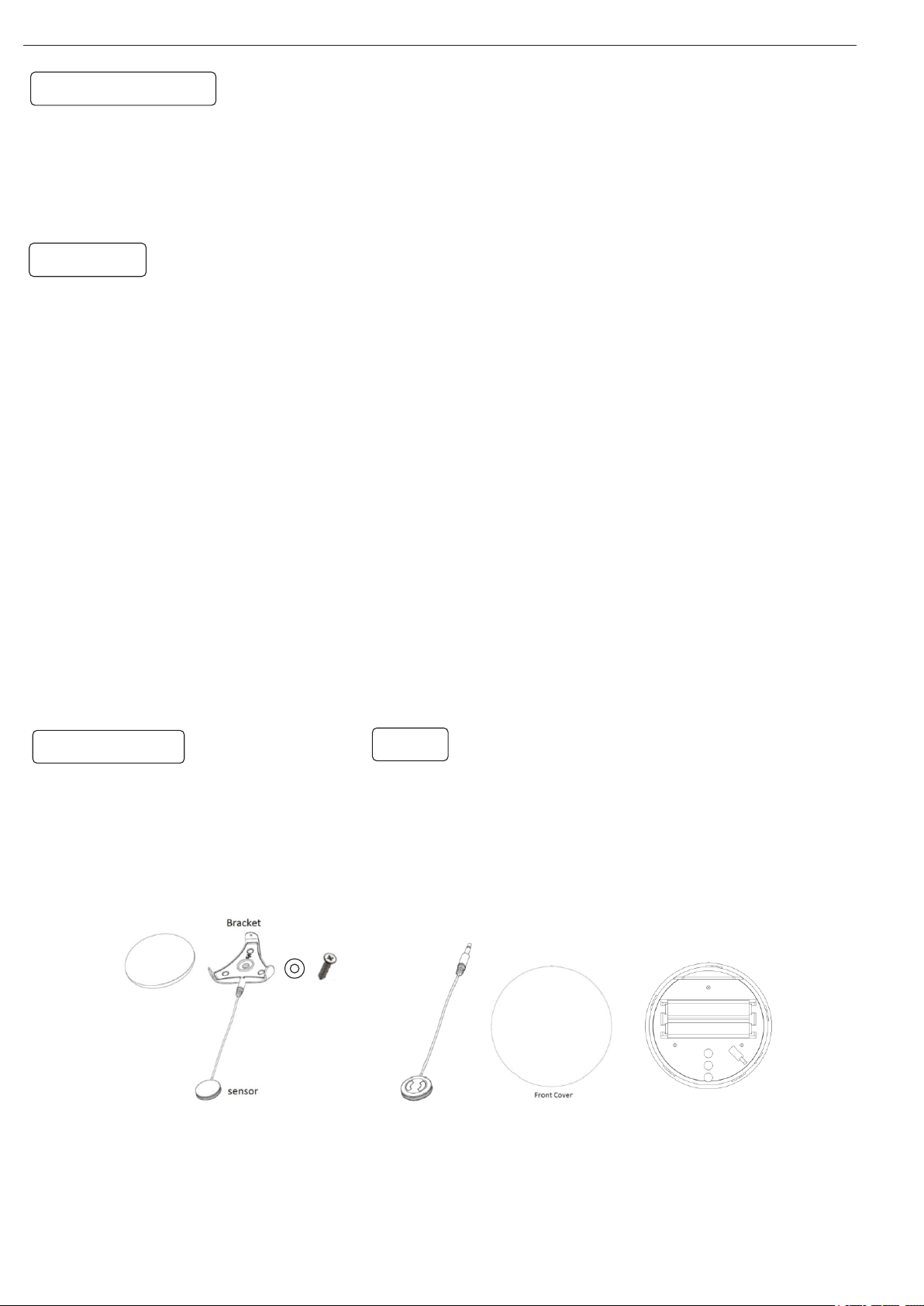
Package content:
ZW1105 Shock Sensor-1pcs
Bracket -1pcs
sensor-1pcs
Adhesive tape -1pcs
Screws for bracket-1pcs
AAA Battery-2pcs
Installation Operation man ual-1 pcs
Adding:
1.Insert battery into the batt ery com partm ent and L ED will s tart
to RGB fl ash slowly, Adding to a z-w ave net work, Q uick pr ess the
program switch (Tamper switch) t hree ti mes , The Gre en LED fla sh ,
inclusion successfu l.
2.Tamper switch closing , The b lue LED fl ash 1ti me/30 sec.
3.Trigger : red led flash
AAA
-
+
AAA
LED
+
-
Tamper sw itch
 Loading...