

Page 1
INFRARED SPECIFICATION DATA
Cinemas • Simultaneous Interpretation • Audio Description • Conferences • Multi-Media Rooms
Boardrooms • Courtrooms • Schools • Universities • Churches
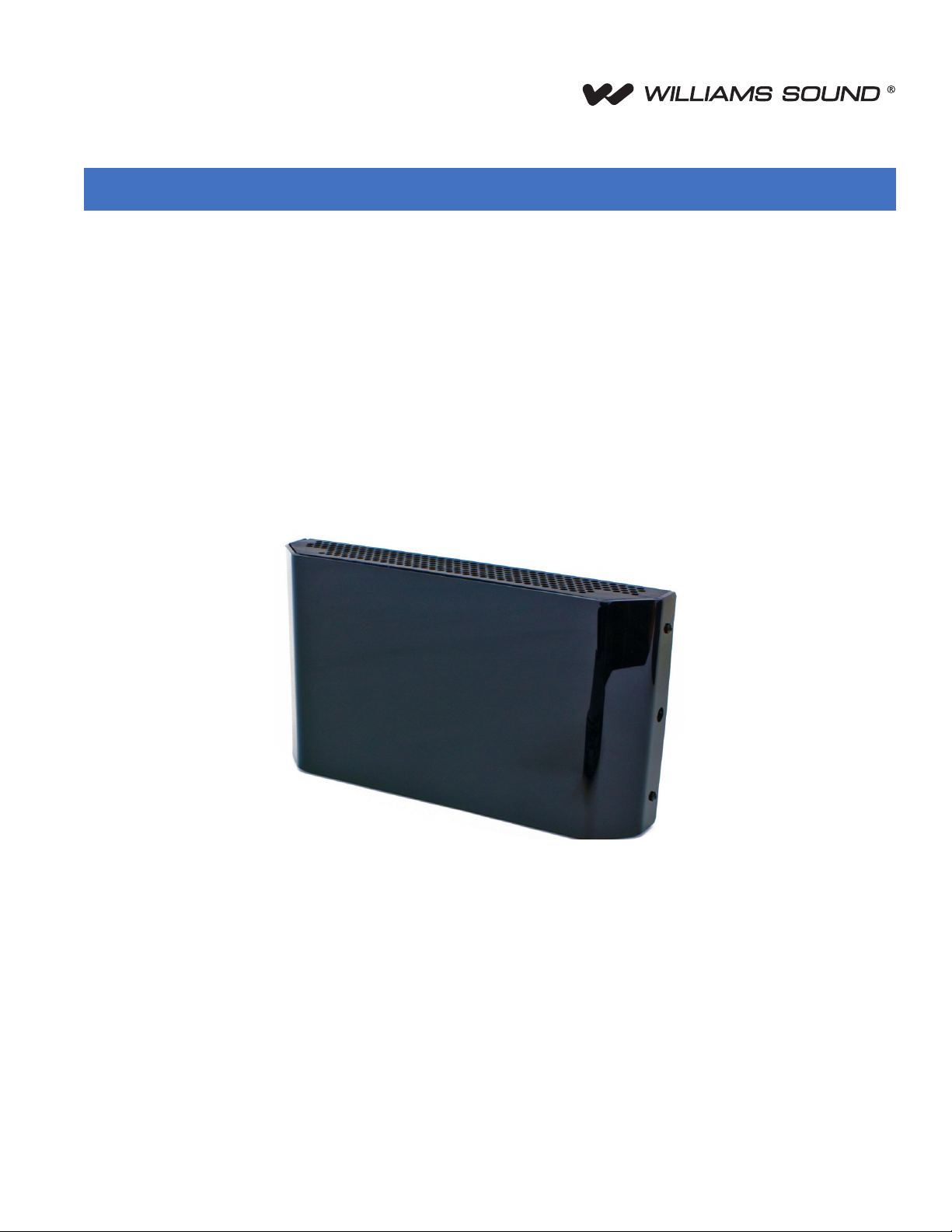
WIR TX90 DC
Large-area multi-channel infrared transmitter
The WIR TX90 DC two channel IR transmitter combines modulator and emitter technology into a single operating unit, which reduces
operating cost and eliminates precious rack space. The WIR TX90 DC transmitter produces a wide-angle infrared signal that
concentrates the IR energy eciently in the listening area. By modulating with frequencies 2.3-3.8 MHz bandwidth, the WIR TX90
DC is less susceptible to radio and lighting interference. Each WIR TX90 DC transmitter can cover up to 30,000 sq ft (2,787 sq m) in
single-channel operation. The coverage area can be easily increased by connecting additional WIR TX9 DC emitters. A wall/ceiling
mounting bracket is included, and stand kits are available for portable operation.
© 2016, Williams Sound, LLC MCAT 234A
Page 2
Infrared Transmitter
WIR TX90 DC Transmitter Specications
Dimensions, Weight:
Color:
Power Supply:
Modulation:
Carrier Frequency:
Emitter IR Power:
Coverage Area:
Signal-to-Noise Ratio:
Frequency Response:
Total Harmonic Distortion:
Compression:
Auto Carrier Shut-O:
11.25” W x 6.25” H x 2.125” D (28.6 cm x 15.9 cm x 5.4 cm), 1.8 lbs (0.8 kg)
Black with white legends, black acrylic lens (optional white enclosure available)
Desktop-style, universal power supply.
Input: 100-240 VAC, 50/60 Hz, 0.6 A. Line cord specied by country of use.
Output: 24 VDC, 1.0 A, 25 W. Barrel connector.
50 ft DC power supply extension cable available (WCA 123).
FM Wideband, +50 kHz deviation max., 50 uS pre-emphasis
Channel A: Selectable, 2.3/3.3 MHz,
Channel B: Selectable, 2.8/3.8 MHz
3.5 W
30,000 sq. ft. (2,787 sq. m) in single channel mode when using the RX22-4 Receiver
19,000 sq. ft (1,765 sq. m) in two channel mode when using the RX22-4 Receiver
11,000 sq. ft (1,022 sq. m) in four channel mode when using the RX22-4 Receiver
3,350 sq. ft (311 sq. m) in single channel mode when using the RX18 Receiver
>75 dB, +3 dB
80 to 15,000 Hz, electrical response
Less than 0.2%, electrical response at 1 kHz
Music preset 1:1, Voice preset 1.5:1, Hearing Assist preset 2:1
20 minute timer shuts o carrier when no audio is present
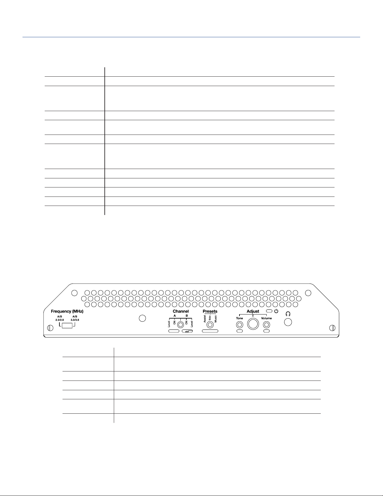
WIR TX90 DC Bottom View
Power Indicator:
Audio Volume Level
Controls:
Audio Indicators:
Carrier LEDs:
Phones Output:
Application Preset:
Tone Control:
Red LED
CH A and CH B Input Level, press to select, 28 dB adjustable range
CH A and CH B Audio Level, yellow LED, ash
2 green LED carrier “on” indicators
3.5mm TRS headphone jack. CH A tip, CH B ring on jack, 32 ohm headphone (min)
Music, Voice, Hearing Assist. Frequency response; Music: Flat; Voice: Mid-range boost; Hearing Assist:
High frequency boost
Press to select, 21 dB adjustable range (1 kHz between low boost/hi-cut and low cut/hi boost).
© 2016, Williams Sound, LLC MCAT 234A
Page 3

Infrared Transmitter
WIR TX90 DC Rear View
Power Input:
Audio Input Connector:
Input Level:
Baseband Output:
Baseband Cable:
Operating Requirements:
Mounting Kits:
Warranty:
Approvals:
Compatible Receivers:
Notes: Specications: Single end input, volume & tone controls at mid point, 1 kHz,
24 VDC, 0.8 A, 25 W
CH A and CH B, 3 wire Phoenix
Balanced or unbalanced, 316 mVRMS (-10 dBV) nominal, 5.7 k Ω input impedance; max input (over
volume range) -21 to +7 dBV.
BNC, 50 Ω, for use with TX9 or TX9 DC only
RG 58 Coax, BNC connectors, maximum 1000 ft. (300 m) length
0-50º C (+32 °F to 122 °F) ambient temperature, non-condensing, non-corrosive atmosphere
Wall or Ceiling Mount: BKT 024 Omnidirectional mount;
Optional: Tripod Stands: SS-11 or SS-6
5 years on transmitter (90 days on accessories)
CE, FCC, RoHS, WEEE
WIR RX22-4 Four-Channel Receiver
WIR RX18 Two-Channel Receiver
“Music” Preset
NOTE: SPECIFICATIONS SUBJECT TO CHANGE WITHOUT NOTICE!
© 2016, Williams Sound, LLC MCAT 234A
Page 4

Infrared Transmitter
Receiver Coverage Area with WIR TX90 DC Transmitter in Single Channel Mode
FEET
FEET
90
80
70
60
50
40
30
20
10
0
-10
-20
-30
-40
-50
-60
-70
-80
-90
10 20 30 40 50 60 70 80 90 100 110 120 130 140 150 160
0
RECEIVER COVERAGE AREA WITH
TX9 DC OR TX90 DC TRANSMITTER
IN SINGLE-CHANNEL MODE
RX22-4 RECEIVER
RX18 RECEIVER
The coverage area for the WIR TX90 DC will vary depending on the receiver being used. The diagram above demonstrates the receiver
coverage when operating a single WIR TX90 DC transmitter in single channel mode. Patterns are direct radiation patterns.
Note: Reections of the infrared light from walls, ceilings and oors may change these patterns.
NOTE: SPECIFICATIONS SUBJECT TO CHANGE WITHOUT NOTICE!
© 2016, Williams Sound, LLC MCAT 234A
Page 5

Infrared Transmitter
Architectural/Engineering Specications
The transmitter shall consist of an all-in-one modulator and emitter operating on switchable carrier frequencies of 2.3/2.8 MHz or 3.3/3.8
MHz. The carrier frequency shall use 50 kHz deviation and 50 µs pre-emphasis.
The transmitter shall have a range of up to 30,000 sq. ft. (2,787 sq. m.) in single channel mode when using the RX22-4 receiver. The
transmitter shall be contained in a metal housing with a durable plastic lens. The transmitter shall be convection cooled without fans. The
transmitter shall include an omni-directional mounting bracket for permanent installations. Additional brackets shall be available for dierent
mounting options.
The transmitter shall provide two channels of selectable carrier frequencies: CH A 2.3/3.3 MHz or CH B 2.8/3.8 MHz. Two transmitters
used in tandem shall provide up 4 simultaneous channels.
The transmitter shall have two Phoenix connectors on the back for balanced or unbalanced line input. All controls and indicators shall be
accessible on the bottom of the panel of the transmitter.
The transmitter shall have three application presets: Music, Hearing Assistance and Voice accessible by thumbscrew adjuster.
There shall be a 3.5 mm stereo headphone jack for monitoring the processed audio before being transmitted.
Two BNC (50 Ω) baseband output jacks shall be provided on the back panel for more coverage needs. The TX9 DC emitter panels must be
used with the TX90 DC transmitter via RG-58 coax cable.
The transmitter shall be powered by an external 24 VDC, 1.0 A power supply. The power connector shall be a barrel type. Additional
emitters shall require individual external power supplies.
The transmitter shall be covered by a ve-year warranty on parts and labor. The transmitter shall be the Williams Sound model WIR TX90 DC.
Domestic Sales
Williams Sound
10300 Valley View Rd
Eden Prairie, MN 55344
Ph: 800-328-6190 / 952-943-2252
FAX: 952-943-2174
Email: info@williamssound.com
Web: www.williamssound.com
International Sales
International Sales Department
Williams Sound
10300 Valley View Rd
Eden Prairie, MN 55344 USA
Phone: +1 952 224 7791
Fax: +1 952 943 2174
Email: info-intl@williamssound.com
Web: www.williamssound.com
800.843.3544 / info@williamssound.com / www.williamssound.com
© 2016, Williams Sound, LLC MCAT 234A
 Loading...