

Page 1
INFRARED SPECIFICATION DATA
Courtrooms • Conferences • Houses of Worship • Universities • Cinema
WIR SYS 7522
Mid-Range Infrared System
This system features the NEW WIR TX75 infrared transmitter,
ensuring participants in a conference room, courtroom,
classroom or other mid-sized venue receive direct, clear
communication of your message without sacricing security.
Includes WIR RX22-4 receivers–ideal for single-or two-channel
applications. The sleek and stylish TX75 is designed to maximize
coverage area up to 5,000 square feet in single-channel mode.
Two additional slaves (sold separately) can be added for
additional coverage of up to 5,000 square feet each (for total
coverage of up to 15,000 square feet). Placing additional slaves
in the same room increases coverage and enhances freedom of
movement. A single CAT-5 cable carries both power and signal
to slaves–truly a one-cable connection. Mounting bracket and
power supply are included.
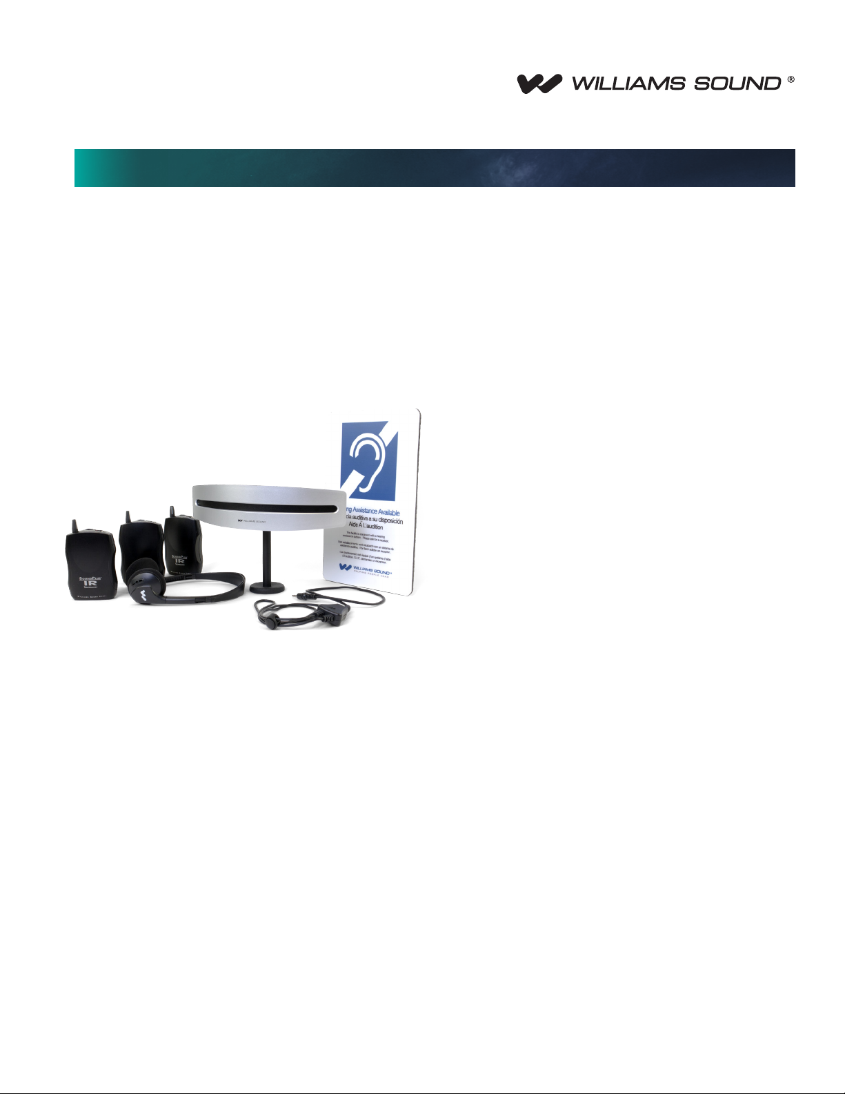
System Includes:
(1) WIR TX75 infrared transmitter
(3) WIR RX22-4 four-channel selectable,
infrared receivers
(3) HED 021 folding headphones
(2) NKL 001 neckloops
(6) BAT 001 AA alkaline batteries
(1) IDP 008 ADA wall plaque
(1) BKT 024 wall / ceiling mounting bracket
(1) TFP 046 international power supply with WLC 004 U.S. mains
AC plug
© 2012, Williams Sound, LLC MCAT 155C
Page 2
Mid-range Infrared System
WIR TX75 Specications
Dimensions, Weight:
Power Supply:
DC Power Input:
Power Indicator:
Sleep/Power Save Mode:
Modulation:
Carrier Frequencies:
Emitter IR Power:
Master Only Coverage Area
(minimum, 1-Ch mode):
Audio Inputs / Controls:
Microphone input:
Microphone gain adjust:
Microphone channel switch:
Audio indicators:
Indicators On/Off:
“to slave” Output/Input:
Slave Status Indicators
(on “to slave” jacks):
Signal-to-Noise Ratio:
Frequency Response:
Total Harmonic Distortion:
Operating Requirements:
Mounting Kit:
Warranty:
10.0" W (25.4 cm) x 3.1" D (7.9 cm) x 1.5" H (3.8 cm) w/o faceplate or 2.5" H (6.4 cm) w/faceplate, 0.6 lbs (0.3kg)
Color:
Black with silver colored silk screen and silver colored faceplate
Optional: white colored faceplate
Desktop style international power supply with IEC line cord, 100-240 VAC input, 50-60Hz, 24W; 48VDC output
2.5mm ID barrel connector, 48 VDC, 0.4A center positive
Green LED
Shuts off carrier when no audio is present for 3 minutes
FM Wideband, ±50kHz deviation max, 50 μS pre-emphasis
TX-75: 2.3MHz (Ch1) and 2.8MHz (Ch2).
TX-75b: 3.3MHz (Ch1) and 3.8MHz (Ch2).
Default at power on = carriers off. Carriers are automatically enabled upon presence of audio.
0.7 W
5,000 sq. ft in single-channel mode with the RX22-4 receiver (464 sq. m)
3,000 sq. ft in single-channel mode with the RX15-2 receiver (279 sq. m)
2,000 sq. ft in single-channel mode with the RX18 receiver (186 sq. m)
Line inputs: RCA jack for Ch1 and Ch2 accept line level, balanced or unbalanced audio
Line in balanced/unbalanced switch: selects balanced or unbalanced line level audio for RCA jacks
3.5 mm, stereo jack with signal and bias connected to tip, electret microphone compatible (4 VDC bias supply with 2.7k ohm
series resistor)
Rotary potentiometer
selects microphone input to Ch1 or Ch2
Yellow LED blinks at nominal audio level. One per channel
2-position switch turns on/off indicator lights
(2) 8p8c RJ45 connectors output 48VDC 0.4A power, baseband RF and a bi-directional RS-485 bus for control and status
communications
Green: Power/Unit Status
Yellow: Transmit/Cable Status
70 dB, (line input)
95Hz to 17.6kHz, -3dB re 1kHz (line inputs)
125Hz to 17.0KHz, -3dB re 1kHz (microphone input)
<1% (1 kHz, nominal deviation, line or microphone input)
0-50° C (32°-122°F)
Wall or Ceiling mount: BKT 024 Omnidirectional mount
Optional: slave linking bar (MLB 003)
2 Years
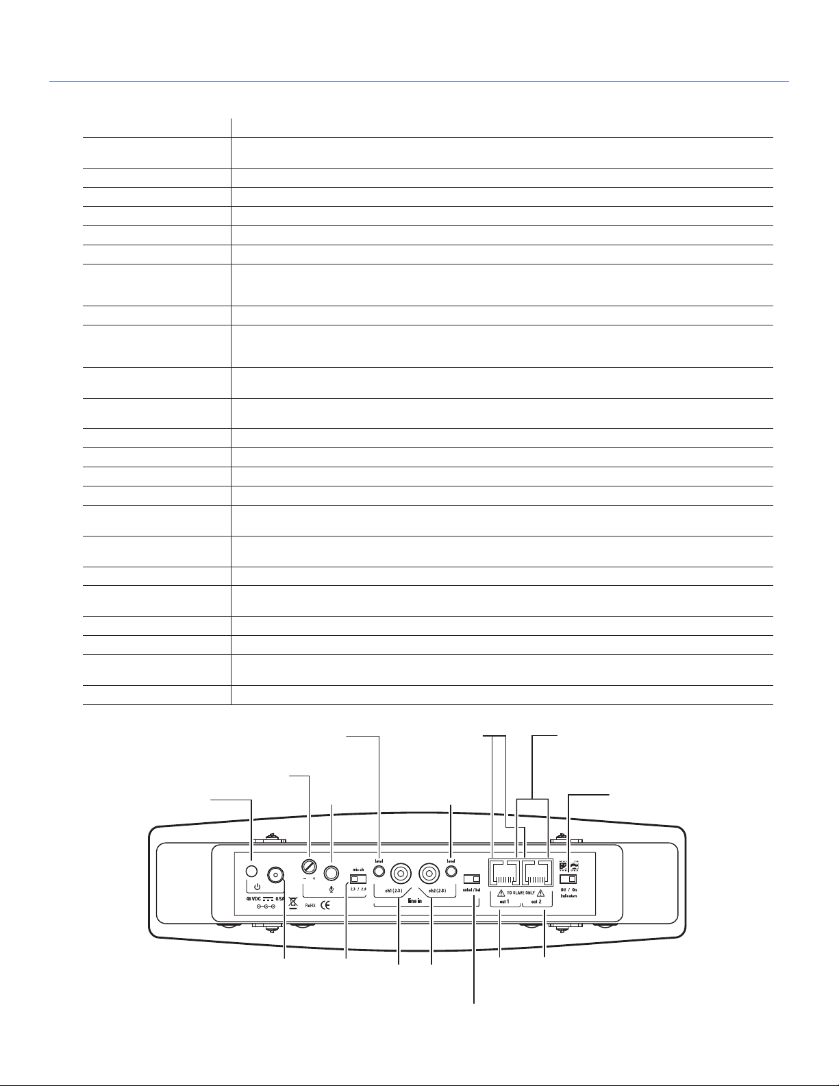
POWER
INDICATOR
CH 1 AUDIO
LEVEL INDICATOR
MIC
ADJUSTMENT
(YELLOW)
POWER IN MIC CHANNEL
MIC IN
SELECTOR
SLAVE TRANSMIT
POWER INDICATOR
RCA IN RCA IN
(2.3) TX-75 (2.8)
(3.3) TX-75b (3.8)
(YELLOW)
CH 2 AUDIO
LEVEL INDICATOR
(YELLOW)
LINE IN BALANCED/
UNBALANCED SELECTOR
TX75 BUS
OUT TO
SLAVE (1)
SLAVE POWER
INDICATOR
(GREEN)
TX75 BUS
OUT TO
SLAVE (2)
INDICATOR
LIGHTS (ON/OFF)
A139
© 2012, Williams Sound, LLC MCAT 155C
Page 3

Mid-range Infrared System
WIR RX22-4 Receiver
EARPHONE
JACK
"ON"
INDICATOR
RX22-4 TOP
CHANNEL
SELECTOR
OFF
ON/OFF
VOLUME SWITCH
RX22-4 FRONT
Receiver Style:
Size:
Weight:
Color and Material:
Lanyard:
Operating Temperature:
Battery Type:
Battery Life:
Battery Drain:
Charging Contacts:
Carrier Frequency:
De-Emphasis:
FM Deviation:
Signal-to-Noise Ratio:
Squelch:
Frequency Response:
Total Harmonic Distortion:
Controls:
Indicators:
Audio Output Jacks:
Audio Output Power:
Acoustic Output:
Sensitivity:
Approvals:
Warranty:
Compatible Headphones/
Earphones:
Body-Pack, dual-lens detector, lanyard
4.1” L x 2.85” W x 1.2” H (104.1 mm x 72.4 mm x 30.4 mm)
4.5 oz (127 g) with batteries
Black
3 ft (.91 m), allows receiver to be worn around the neck
-10° C to +50° C
2 x AA, alkaline (BAT 001) or NiMH (BAT 026)
Alkaline: 60 hours, NiMH: 30 hours/charge
25 mA, nominal
For use only with CHG 3512
Channel 1: 2.3 MHz, Channel 2: 2.8 MHz
Channel 3: 3.3 MHz, Channel 4: 3.8 MHz
50 uS
±50 kHz
60dB min.
Receiver squelches (mutes) at 40 dB S/N ratio
25 Hz to 16 KHz, +1 dB, -3 dB, electrical response
Less than 1%, electrical response
ON/OFF/VOLUME: combination thumbwheel knob
Channel Selector: four-position rotary switch
Red LED “ON” indicator, ashes to indicate Low battery
3.5 mm stereo mini phone jack Accepts 3.5 mm mono or stereo phone plug
15 mW max at 32 Ω
125 dB SSPL90 with HED 021; 110 dB SSPL90 w/ EAR 013
Better than 1 nW/cm2 for 40 dB signal-to-noise ratio
CE, FCC, RoHS, WEEE
5 years on receiver, 90 days on accessories
Mono or stereo, 8-32 ohms, 3.5 mm mini phone plug, HED 021, HED 026,
EAR 013, EAR 014, EAR 022, NKL 001
A137
© 2012, Williams Sound, LLC MCAT 155C
Page 4

Mid-range Infrared System
Bid Specs
WIR TX75/b
The Williams Sound WIR TX75 Infrared Transmitter shall consist
of an all in one modulator and emitter operating on 2.3MHz and/
or 2.8MHz. The WIR TX75b shall operate at 3.3 MHz and/or 3.8
MHz. The carrier frequency shall use 50kHz deviation and 50 μS
pre-emphasis.
The TX75 shall have a minimum coverage of 5,000 sq ft with the
WIR RX22-4 receiver in single channel mode.
The TX75 shall be housed in a heavy-duty black plastic enclosure
with a durable infra-red transparent front lens. It shall be convection
cooled without fans. The Transmitter includes an omni-directional
mounting bracket for various permanent installations.
The TX75 shall have a line level RCA input for each of the channels.
Each channel shall have an audio input level LED. There shall be
a single 3.5mm microphone input with gain control. The mic input
shall have a channel selector switch.
The Transmitter shall have a switch to turn off all indicator LED’s.
There shall be a switch for selecting either balanced or unbalanced
line level inputs.
The TX75 shall have two RJ45 outputs to supply power and
baseband signal to two WIR TX75-S slave emitters via CAT-5 cable.
A single CAT-5 cable supplies power, signal and digital control to the
slave unit up to 100 ft from the Transmitter.
The Transmitter shall be powered by a 48VDC universal power
supply, 50-60Hz, 100-240 VAC input, 24W.
The TX75 shall be covered by a two-year parts and labor warranty,
90 days on accessories.
This Transmitter shall be the Williams Sound model WIR TX75.
WIR RX22-4
The receiver shall be a body-pack type with IR detector lens
behind face of the unit. The unit shall have a lanyard for hands-free
operation. The receiver shall have a rotary-type volume control. The
receiver shall operate for 60 hours with two AA alkaline batteries
and for 30 hours per charge with NiMH AA batteries. The receiver
shall be charged without battery removal via charger contacts in
the case. A drop-in charger accessory shall recharge the batteries
in 16 hours when used with CHG 3512 charger. The receiver
shall be housed in an impact resistant plastic case with a hinged
battery door that does not separate from the receiver. The receiver
shall receive 2.3 MHz, 2.8 MHz, 3.3 MHz or 3.8 MHz modulated
IR signals with 50 μS de-emphasis. The receiver shall have a
3.5 mm stereo phone jack and accommodate low-impedance
mono or stereo earphones and headphones. The receiver shall
accommodate neckloop telecoil couplers. The receivers shall
provide 125 dB SSPL90 output with HED 021 headphone and 110
dB SSPL90 with EAR 013 earbud-type earphone.
The system electrical frequency response shall be 25 Hz to 16 kHz,
+1, -3 dB and the S/N ratio shall be 60 dB. The receiver shall have
CE, FCC RoHS and WEEE approval. The receiver shall be covered
by a ve-year parts and labor warranty, excluding earphones,
headphones, batteries and chargers.
The receiver shall be the Williams Sound model WIR RX22-4.
NOTE: SPECIFICATIONS SUBJECT TO CHANGE WITHOUT NOTICE!
Domestic Sales
Williams Sound
10300 Valley View Rd.
Eden Prairie, MN 55344
Ph: 800-328-6190 / 952-943-2252
FAX: 952-943-2174
Email: info@williamssound.com
Web: www.williamssound.com
International Sales
International Sales Department
Williams Sound
10300 Valley View Rd.
Eden Prairie, MN 55344 USA
Phone: +1 952 943 2252
Fax: +1 952 943 2174
Email: info@williamssound.com
Web: www.williamssound.com
800.843.3544 / info@williamssound.com / www.williamssound.com
© 2012, Williams Sound, LLC MCAT 155C
 Loading...